

More Related Content
Viewers also liked
Viewers also liked (9)
615 616
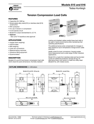
- 1. Tedea-Huntleigh www.vpgtransducers.com 1 Models 615 and 616 Technical contact in Americas: lc.usa@vishaypg.com; Europe: lc.eur@vishaypg.com; Asia: lc.asia@vishaypg.com Document No.: 12066 Revision: 26-Jul-2012 Tension Compression Load Cells FEATURES • Capacities 50–1000 kg • Nickel-plated alloy steel (615) or stainless steel (616) construction • IP67 protection • For use in tension or compression • 6-wire (sense) circuit • Model 615 output standardised to ±0.1% • Optional ❍❍ EEx ia IIC T4 hazardous area approval APPLICATIONS • Hopper (tank weighing) • Hybrid scales • Belt weighing • Lever arm conversions • Material testing machines • Vibrations filling equipment • Dynamometers DESCRIPTION Models 615 and 616 are tension compression load cells which share the same dimensions. Humidity-resistant coating and shielded cables enable these load cells to be used in harsh environments while maintaining their operating specifications. The additional sense wires compensate for changes in lead resistance due to temperature change and/or cable extension. Ideally suited for lever conversions, hanging scales, force measurement and a wide range of other industrial applications. Model 616 is made from stainless steel and has bonded covers for additional protection (except 50 kg). An alternative lower cost version is made from alloy steel (Model 615), with riveted covers. OUTLINE DIMENSIONS in millimeters Models 615 and 616—50 kg only Models 616—except 50 kg Tension Compression Load Cells Document No.: 12066 Revision: 26-Jul-2012 Models 615 and 616
- 2. Tedea-Huntleigh www.vpgtransducers.com 2 Models 615 and 616 Technical contact in Americas: lc.usa@vishaypg.com; Europe: lc.eur@vishaypg.com; Asia: lc.asia@vishaypg.com Document No.: 12066 Revision: 26-Jul-2012 Tension Compression Load Cells SPECIFICATIONS PARAMETER VALUE UNIT Accuracy class Non-Approved G Maximum no. of intervals (n) 1000 3000 Rated capacity—R.C. (Emax) 50, 100, 150, 200, 300, 500, 750, 1000* kg Rated output—R.O. 2.0 mV/V Rated output tolerance 0.002 ±mV/V Zero balance 0.2 ±mV/V Zero return, 30 min. 0.05 0.017 ±% of applied load Total error (per OIML R60) 0.05 0.02 ±% of rated output Temperature effect on zero 0.01 0.004 ±% of rated output/°C Temperature effect on output 0.003 0.0012 ±% of load/°C Temperature range, compensated –10 to +40 °C Temperature range, safe –30 to +70 °C Maximum safe central overload 150 % of R.C. Ultimate central overload 300 % of R.C. Excitation, recommended 10 VDC or VAC RMS Excitation, maximum 15 VDC or VAC RMS Input impedance 400±20 Ω Output impedance 350±3 Ω Insulation resistance >2000 MΩ Cable length 3.0 m Cable type 6-wire, PVC, single floating screen** Standard Construction 615—alloy steel 616—stainless steel Environmental protection IP67 * 616 does not include 50 kg ** 616 has polyurethane jacket braided cable with dual floating screen All specifications subject to change without notice. Wiring Schematic Diagram +ve Input (Green) +ve Output (Red) –ve Input (Black) –ve Sense (Brown) –ve Output (White) (Balanced bridge configuration) +ve Sense (Blue)
- 3. Vishay Precision Group, Inc. www.vpgsensors.com 1 Legal Disclaimer Notice Document No.: 63999 Revision: 15-Jul-2014 Disclaimer ALL PRODUCTS, PRODUCT SPECIFICATIONS AND DATA ARE SUBJECT TO CHANGE WITHOUT NOTICE. Vishay Precision Group, Inc., its affiliates, agents, and employees, and all persons acting on its or their behalf (collectively, “VPG”), disclaim any and all liability for any errors, inaccuracies or incompleteness contained herein or in any other disclosure relating to any product. The product specifications do not expand or otherwise modify VPG’s terms and conditions of purchase, including but not limited to, the warranty expressed therein. VPG makes no warranty, representation or guarantee other than as set forth in the terms and conditions of purchase. To the maximum extent permitted by applicable law, VPG disclaims (i) any and all liability arising out of the application or use of any product, (ii) any and all liability, including without limitation special, consequential or incidental damages, and (iii) any and all implied warranties, including warranties of fitness for particular purpose, non-infringement and merchantability. Information provided in datasheets and/or specifications may vary from actual results in different applications and performance may vary over time. Statements regarding the suitability of products for certain types of applications are based on VPG’s knowledge of typical requirements that are often placed on VPG products. It is the customer’s responsibility to validate that a particular product with the properties described in the product specification is suitable for use in a particular application. You should ensure you have the current version of the relevant information by contacting VPG prior to performing installation or use of the product, such as on our website at vpgsensors.com. No license, express, implied, or otherwise, to any intellectual property rights is granted by this document, or by any conduct of VPG. The products shown herein are not designed for use in life-saving or life-sustaining applications unless otherwise expressly indicated. Customers using or selling VPG products not expressly indicated for use in such applications do so entirely at their own risk and agree to fully indemnify VPG for any damages arising or resulting from such use or sale. Please contact authorized VPG personnel to obtain written terms and conditions regarding products designed for such applications. Product names and markings noted herein may be trademarks of their respective owners. Copyright Vishay Precision Group, Inc., 2014. All rights reserved. Disclaimer Legal Disclaimer Notice