SlideShare a Scribd company logo
1 of 52
Download to read offline
MXE ELECTRIC ACTUATORS
MAXIMUM DURABILITYMAXIMUM DURABILITY
S SOLID BEARING
P PROFILED RAIL
ELECTROMATE
Toll Free Phone (877) SERVO98
Toll Free Fax (877) SERV099
www.electromate.com
sales@electromate.com
Sold & Serviced By:
2 1.800.328.21742 1.800.328.21742 1.800.328.2174
S-SOLID BEARING
•Large bearing surface contact area optimizes
stress distribution on bearing for long service life
•Large carrier mounting pattern for more load
stability and compatibility with existing BCS
applications
•Engineered bearing material does not require
additional lubrication
• Solid bearings are field replaceable
P-PROFILED RAIL
•THK® Caged Ball® bearings with reduced friction for
reliable service life
•High load and bending moment capacities
•Low profile to fit your application
•High precision bearings feature smooth, low
breakaway motion
The MXE electric actuator is exactly what
you expect from the industry’s number
one rodless supplier. Designed with our
exclusive ENDURANCE TECHNOLOGYSM
features, the MX delivers superior per-
formance to meet the most demanding
applications. Nobody knows rodless like
Tolomatic, and the MX proves it.
THE MXE ELECTRIC ACTUATOR – DESIGNED TO OUTLAST
EVERY RODLESS ACTUATOR ON THE MARKET
• DURABLE BEARINGS. Two bearing choices to match your application
needs. Solid bearing design optimizes stress distribution for optimal
performance. Profiled rail design uses THK® Caged Ball® technology to
reduce friction and extend actuator life.
• DURABLE BANDS. Stainless steel bands are stronger and will not
elongate like elastomer (non-metallic) bands, providing a reliable seal
over the life of the actuator.
Choose from our broad line of MX products: MXP pneumatic rodless cylinders and
MXE electric actuators. World class product performance, five days built-to-order and
legendary customer service . . . what you expect from the leader . . . Tolomatic!
ELECTROMATE
Toll Free Phone (877) SERVO98
Toll Free Fax (877) SERV099
www.electromate.com
sales@electromate.com
Sold & Serviced By:
www.tolomatic.com/mxe 3www.tolomatic.com/mxe 3
SELECT THE PERFORMANCE YOU NEED
MOMENT & LOAD CAPACITY COMPARISON
Bearing
Type Solid Bearing Profiled Rail
Moment Moderate High
Capacity + Mx Capacity
Ideal • Side Loads • High Moment Loads
Applications • Moderate or Light • High Speeds with
Loads Heavy Loads
• Guided Loads • High Precision
Product Features Page 4 Page 6
Tolomatic MX
Electric
Actuator Model
Graph for model comparison, data from MXE40 actuator
Choose from: • Two Bearing Models • Six Actuator Sizes • Built to Your Specified Stroke Length
0
1,000
2,000
PS
MAX.BENDINGMOMENT(in.-lbs.)
1,800
1,600
1,400
1,200
800
600
400
200
224
Nm
112
Nm
MAX.Fz[LOAD](lbs.)MAX.Fz[LOAD](lbs.)
225
736
FzMx
Fz
MyMy
Mz
Mx My Mz Fz
TABLE OF CONTENTS
Introduction..........................................2
Comparison..........................................3
S Solid Bearing Features......................4
P Profiled Rail Features........................6
Motion Control Systems Overview........8
S Moment and Load Capacity...........10
P Moment and Load Capacity...........11
Specifications.....................................12
Tube Clamp Reqirements...................15
Screw Critical Speed Capacities.........16
S Solid Bearing Dimensions...............26
P Profiled Rail Bearing Dimensions....28
Inline Motor Mounting Dimensions......30
S Reverse Parallel Motor Mounting
Dimensions.........................................34
P Reverse Parallel Motor Mounting
Dimensions.........................................39
Switches ............................................44
S Adjustment Procedures..................47
Compile Application Requirements.....48
Selection Guidelines...........................49
Service Parts......................................50
Ordering.............................................51
4 1.800.328.21744 1.800.328.21744 1.800.328.21744 1.800.328.21744 1.800.328.21744 1.800.328.21744 1.800.328.2174
S SOLID BEARING Endurance Technology features are
designed for maximum durability to
provide extended service life.
DUST WIPER
•Formed end cap and
side dust wipers keep
contaminants from entering
the actuator’s internal area
RETAINED DUST BAND
•Retained dust band keeps contaminants from entering
the actuator interior, protecting components for
reduced maintenance and increased uptime
LARGE FLEXIBLE
MOUNTING PATTERN
•Carrier gives more load stability
•Compatibility with existing BCS
applications
•More fastening options
STAINLESS STEEL BAND
•Exterior dust band
made of fatigue
resistant
stainless
steel
STAINLESS STEEL IS
DURABLE, FLEXIBLE AND
CORROSION RESISTANT
NON-WEAR BAND RETENTION
•Magnetically retained band is not subject to
wear as are mechanically retained systems
MULTIPLE SCREW TECHNOLOGIES
YOU CAN CHOOSE:
•Solid nuts of engineered resins
for quiet performance at the
lowest cost - 5 choices
•Ball nuts offer positioning
accuracy and repeatability
with longer life, low-backlash
available - 3 choices
ELECTROMATE
Toll Free Phone (877) SERVO98
Toll Free Fax (877) SERV099
www.electromate.com
sales@electromate.com
Sold & Serviced By:
www.tolomatic.com/mxe 5www.tolomatic.com/mxe 5www.tolomatic.com/mxe 5www.tolomatic.com/mxe 5www.tolomatic.com/mxe 5www.tolomatic.com/mxe 5
…MAXIMUM DURABILITY
OPTIONS
AUXILIARY CARRIER DC
• 2X higher Fz (load) capacity
• High bending moment capacity
FLOATING MOUNT FL
•Compensates for non-parallelism between MX
actuator and externally guided load
TUBE CLAMPS TC
•Used for intermediate support
•Flush with bottom of actuator
to retain low profile
•Drop-in, adjustable mounting locations
(MXE16 uses T-nuts with mounting plates)
MOUNTING PLATES MP
•To provide clearance for motor and mount
•Use in conjunction with tube clamps
SWITCHES
•Wide variety of sensing choices: Reed, Solid
State PNP or NPN, all available normally open
or normally closed
•Flush mount, drop-in installation
•Bright LEDs, power & signal indication
•CE rated, RoHS compliant
NOTE: Boxed letters
indicate ordering codes
TRAPEZOIDAL BEARINGS
•Trapezoidal design maximizes bearing
surface area for less pressure on
bearing surfaces; less pressure results
in less wear
•Engineered bearing material has
low static and dynamic friction with
low wear properties for long lasting,
smooth operation
•Bearings are field replaceable for
extended service life
INCH OR METRIC MOUNTING
•Your choice of inch (US standard) or metric
mounting to the carrier
NON-BINDING BEARING ARMS
•Bearings are tensioned
indirectly, providing bind
free adjustment
YOUR MOTOR HERE
YOU CAN CHOOSE:
•Motor or gearbox supplied and installed by Tolomatic
•Specify the device to be installed and actuator ships
with proper mounting hardware - MXE is a “Your Motor
Here” actuator for easy in-line motor installation. Check
our website (www.tolomatic.com/ymh) for complete
YMH information
•Specify and ship your device to Tolomatic for factory
installation
MOTOR ORIENTATION
YOU CAN CHOOSE:
•In-line option directly couples the driving shaft
and is a one-piece housing construction for
optimum alignment and support of the motor
•Reverse-parallel option minimizes the overall
length and offers a 1:1 or 2:1 belt ratio
INTERNAL MAGNETS
•Standard feature that allows
sensor installation on the
open side or bottom of the
extrusion
ELECTROMATE
Toll Free Phone (877) SERVO98
Toll Free Fax (877) SERV099
www.electromate.com
sales@electromate.com
Sold & Serviced By:
6 1.800.328.21746 1.800.328.21746 1.800.328.21746 1.800.328.21746 1.800.328.2174
P PROFILED RAIL Endurance Technology features are
designed for maximum durability to
provide extended service life.
INTERNAL MAGNETS
•Standard feature that allows
sensor installation on the
open side or bottom of the
extrusion
INCH OR
METRIC
MOUNTING
•Your choice of
inch (US standard) or
metric mounting to
the carrier
CAGED BALL®
BEARINGS
•THK® Caged Ball® bearings are
used to reduce friction and extend
actuator life
•Caged Ball® technology creates a
grease pocket between ball elements,
reducing friction, noise and maintenance
•Large permissible moment loads
•High speed operation, low heat
generation
•High precision, smooth, low friction
motion
DUST WIPER
•Formed end cap and
side dust wipers keep
contaminants from entering
the actuator’s internal area
STAINLESS STEEL BAND
•Exterior dust band made
of fatigue resistant
stainless steel
STAINLESS STEEL IS
DURABLE, FLEXIBLE AND
CORROSION RESISTANT
ELECTROMATE
Toll Free Phone (877) SERVO98
Toll Free Fax (877) SERV099
www.electromate.com
sales@electromate.com
Sold & Serviced By:
www.tolomatic.com/mxe 7www.tolomatic.com/mxe 7www.tolomatic.com/mxe 7www.tolomatic.com/mxe 7
…MAXIMUM DURABILITY
OPTIONS
AUXILIARY CARRIER DC
• 2X higher Fz (load) capacity
• High bending moment capacity
TUBE CLAMPS TC
•Used for intermediate support
•Flush with bottom of actuator
to retain low profile
•Drop-in, adjustable mounting locations
(MXE16 uses T-nuts with Mounting Plates)
MOUNTING PLATES MP
•To provide clearance for motor and mount
•Use in conjunction with tube clamps
SWITCHES
•Wide variety of sensing choices: Reed, Solid
State PNP or NPN, all available normally open
or normally closed
•Flush mount, drop-in installation
•Bright LEDs, power & signal indication
•CE rated, RoHS compliant
NOTE: Boxed letters
indicate ordering codes
NON-WEAR BAND RETENTION
•Magnetically retained band is not
subject to wear as are mechanically
retained systems
•Immediate band engagement and
release results in less drag on carrier
for lower friction force during initial carrier
movement
LOW CARRIER HEIGHT
•Reduces overall actuator envelope
•Large mounting pattern for high load stability
YOUR MOTOR HERE
YOU CAN CHOOSE:
•Motor or gearbox supplied and installed by Tolomatic
•Specify the device to be installed and actuator
ships with proper mounting hardware - MXE is a
“Your Motor Here” actuator for easy in-line motor
installation. Check our website (www.tolomatic.com/
ymh) for complete YMH information
•Specify and ship your device to Tolomatic for factory
installation
MOTOR ORIENTATION
YOU CAN CHOOSE:
•In-line option directly couples the driving shaft
and is a one-piece housing construction for
optimum alignment and support of the motor
•Reverse-parallel option minimizes the overall
length and offers a 1:1 or 2:1 belt ratio
MULTIPLE SCREW TECHNOLOGIES
YOU CAN CHOOSE:
•Solid nuts of engineered resins
offer quiet performance at the
lowest cost - 5 choices
•Ball nuts offer positioning
accuracy and repeatability
with longer life, low-backlash
available - 3 choices
RETAINED DUST BAND
•Retained dust band keeps
contaminants from entering
the actuator interior, protecting
components for reduced
maintenance and increased uptime
ELECTROMATE
Toll Free Phone (877) SERVO98
Toll Free Fax (877) SERV099
www.electromate.com
sales@electromate.com
Sold & Serviced By:
8 1.800.328.21748 1.800.328.21748 1.800.328.2174
HUB MULTI-AXIS MOTION HUB WITH I/O
BOB BREAK OUT BOARD
MRS STEPPER SYSTEM
STEPPER MOTORS
NEMA 23-Frame and 34-Frame MRS Stepper Motors
STEPPER DRIVE AND
CONTROLLER
The DS [STAC6-S] & SI [STAC6-Si]
represent the latest developments in
stepper drive technology, incorporating
features that derive the highest
performance from today’s stepper
motors. Anti-resonance and waveform
damping control algorithms provide
excellent performance.
• Current Output 0.5 to 6.0 A
• 90-135 VAC Input
• 167V Bus
• Set-up and configuration software
• Configurable idle current reduction
• External control options
• Pulse and direction
• Analog command signal
• Host command via RS232/485
• Integral control options -
Si ProgrammerTM
- intuitive easy-to-use
graphical programming language
•Designed for
increased torque
and acceleration
rates over a wider
speed range
•Standard NEMA
frame sizes
(23 and 34)
MMI OPERATOR INTERFACE
• Networks Stepper products
for multi-axis motion
applications.
STEPPER ACCESSORIES
• Connects the I/O points of the
DS [STAC6-S] &
SI [STAC6-Si]
• Allows visual setup of the
panel to show a particular
action taking place, or to
prompt the user to make a
decision or provide information
such as move distance, move
speed, repeat count.
• Speeds up to 3,000 RPM
• High resolution (up to 51,200 steps per rev)
• Holding torque to 1845 oz-in (13.03 Nm)
• 2000 line Quadrature encoder option
• 10 ft. power cables with connector
pre-wired
DS
[ ]
SI
[ ]
! !
• ANTI-RESONANCE
Achieves higher speeds and better
torque utilization
! Please note the Tolomatic ordering codes. Use these codes when ordering stepper components from Tolomatic
(Applied Motion Products model equivalents appear in [brackets])
• COMMAND SIGNAL SMOOTHING
Soften effect of changes in velocity
and direction
• MICROSTEP EMULATION
Smooth, high resolution motion
across range of speeds
• TORQUE RIPPLE SMOOTHING
Adjusts current waveform to reduce
low speed torque ripple, providing
smoother motion at low speeds
• SELF TEST Measure motor
parameters automatically to
optimize system performance
ADD YOUR MOTION CONTROL SYSTEM TO THE MXE or
INDUSTRY
STANDARD
MOUNTING
HYBRID
MOTOR
DESIGN
LATEST IN
MICROSTEPPING
TECHNOLOGY
www.tolomatic.com/mxe 9www.tolomatic.com/mxe 9
MRV SERVO SYSTEM
DIGITAL SERVO DRIVE
AND CONTROLLER
Designed by Tolomatic, the Axiom+ PV
combines the functions of a servo drive,
motion controller and programmable logic
controller in a single package. Our all-
in-one design eliminates the confusion
of multiple software packages, removes
discrete wiring or network programming
between controllers, and simplifies
application programming.
The free Windows®
-based software
package programs the PLC functions in
a standard ladder logic environment and
the motion control functions in a simple
graphical motion editor.
SERVO MOTORS
The MRV series of brushless servo
motors is available in a wide range of
torque outputs to meet your demanding
applications. These motors are designed
for precision motion profiles, low inertia,
maximum power density and long
continuous life.
SPECIFICATIONS:
TORQUE Max. Rotor
Cont. Peak Speed Inertia
(lb-in) (lb-in) (RPM) (lb-in2
)
MRV11 3 12 5000 0.02
MRV21 4 11 6000 0.05
MRV22 8 22 6000 0.10
MRV23 11 33 6000 0.14
MRV24 15 47 6000 0.19
MRV31 17 85 6000 0.38
MRV32 30 150 6000 0.69
MRV33 44 220 6000 1.00
MRV51 80 240 3000 2.53
SPECIFICATIONS:
PV10 PV20 PV30
Input Line 95 - 250 VAC, 1Ø or 3Ø
Input Hz 47 - 63 Hz
Output Current Peak (Apeak) 10 20 30
Output Current Cont (Acont) 5 10 15
Output Power Cont (kW) 1.4 2.8 4.2
Discrete Inputs 15, optically isolated 5-25VDC
Discrete Outputs 8, optically isolated 5-25VDC
Analog Inputs 1, 14-bit Differential ±10VDC
•1000 line quadrature industry standard
incremental encoder feedback
•Standard NEMA
frame sizes
(17, 23, 34 and 56) •Thermistor provides
over temperature
protection
•IP65 rated
SELECT A COMPLETE SYSTEM FROM TOLOMATIC
• FLUX VECTOR CURRENT CONTROL
Provides closed loop motor control
of torque producing current by
sensing motor current in each
individual motor phase. This gives
a high bandwidth torque response
over the full speed range with high
efficiency and minimal phase lag
• PLUGGABLE SCREW TERMINAL BLOCKS
Allows easier termination, quick
connection or removal of wiring and
direct access to signals for testing
with a meter
• MODBUS RTU COMMUNICATIONS
Standard Modbus RTU is built
into the drive for communications
to other controllers or operator
interfaces
• AMPLIFIER ONLY OPTION
The DV version is for use with an
external controller that provides
analog velocity, analog torque or
step commands
HIGH RESOLUTION ENCODER
INDUSTRY
STANDARD
MOUNTING
INTEGRAL
PROTECTION
INNOVATIVE
SERVO
TECHNOLOGY
ELECTROMATE
Toll Free Phone (877) SERVO98
Toll Free Fax (877) SERV099
www.electromate.com
sales@electromate.com
Sold & Serviced By:
10 1.800.328.217410 1.800.328.217410 1.800.328.2174
The above ratings are the maximum values for shock-free, vibration-
free operation in a typical industrial environment, which must not be
exceeded even in dynamic operation. Contact Tolomatic for assistance
in selecting the most appropriate actuator for your application. =
Mxmax
LF
Mx +
Mymax
My +
Mzmax
Mz +
Fymax
Fy + < 1
Fzmax
Fz
With combined loads, LF
must not exceed the value 1.
Ratings were calculated with the following conditions:
1.) Coupling between carriers is rigid.
2.) Load is equally distributed between carriers.
STANDARD CARRIER
S SOLID BEARING MOMENT AND LOAD CAPACITY
*At minimum “D” distance see graph below for complete information
DC AUXILIARY CARRIER
3.) Coupling device applies no
misalignment loads to carriers.
AUXILIARY CARRIER BENDING
MOMENTS WITH INCREASED “D”
DISTANCE BETWEEN CARRIERS
“D”DISTANCE BETWEEN
CARRIERS
“D”DISTANCE BETWEEN
CARRIERS
SIZE
MAXIMUM BENDING MOMENTS MAX. LOAD
Mx My Mz Fz
in-lbs N-m in-lbs N-m in-lbs N-m lbf N
16 22 2.5 19 2.1 25 2.8 35 156
25 60 6.8 110 12.4 34 3.8 70 311
32 100 11.3 350 39.5 140 15.8 150 667
40 275 31.1 600 67.8 220 24.9 225 1,001
50 315 35.6 1,155 131.0 341 38.5 315 1,401
63 585 66.1 2,340 264.0 520 58.8 520 2,313
SIZE
“D”
MINIMUM
MAXIMUM BENDING MOMENTS* MAX. LOAD
Mxa Mya Mza Fza
in mm in-lbs N-m in-lbs N-m in-lbs N-m lbf N
16 5.0 127 44 5.0 175 19.8 175 19.8 70 311
25 6.0 152 120 13.6 420 47.5 420 47.5 140 623
32 7.0 178 200 22.6 1,050 119.0 1,050 119.0 300 1,334
40 8.5 216 550 62.1 1,913 216.0 1,913 216.0 450 2,002
50 8.6 218 630 71.2 2,709 306.0 2,709 306.0 630 2,802
63 13.0 330 1,170 132.0 6,760 764.0 6,760 764.0 1,040 4,626
30
25
20
15
10
5
700
600
500
400
300
200
0 2,500
2500 500 750 1,000 1,250 1,500 1,750
5,000 7,500 10,000
Mya & Mza MOMENT (in-lbs)
Mya & Mza MOMENT (N-m)
DISTANCEBETWEEN
CARRIERS(in)
DISTANCEBETWEEN
CARRIERS(mm)
12,500 15,000
16
25 32
40
16
25 32
40
5050
6363
ELECTROMATE
Toll Free Phone (877) SERVO98
Toll Free Fax (877) SERV099
www.electromate.com
sales@electromate.com
Sold & Serviced By:
www.tolomatic.com/mxe 11www.tolomatic.com/mxe 11
STANDARD CARRIER
*At minimum “D” distance see below for complete information
P PROFILED RAIL MOMENT AND LOAD CAPACITY
DC AUXILIARY
CARRIER
The above ratings are the maximum values for shock-free, vibration-
free operation in a typical industrial environment, which must not be
exceeded even in dynamic operation. Contact Tolomatic for assistance
in selecting the most appropriate actuator for your application. =
Mxmax
LF
Mx +
Mymax
My +
Mzmax
Mz +
Fymax
Fy + < 1
Fzmax
Fz
With combined loads, LF
must not exceed the value 1.
Ratings were calculated with the following conditions:
1.) Coupling between carriers is rigid.
2.) Load is equally distributed between carriers.
3.) Coupling device applies no
misalignment loads to carriers.
AUXILIARY CARRIER BENDING
MOMENTS WITH INCREASED “D”
DISTANCE BETWEEN CARRIERS
“D”DISTANCE BETWEEN
CARRIERS
“D”DISTANCE BETWEEN
CARRIERS
SIZE
MAXIMUM BENDING MOMENTS MAXIMUM LOAD
Mx My Mz Fy Fz
in-lbs N-m in-lbs N-m in-lbs N-m lbf N lbf N
16 39 4.5 339 38.3 339 38.3 217 966 217 966
25 126 14.3 502 56.7 377 42.6 449 1,996 449 1,996
32 226 25.6 1,344 152.0 1,344 152.0 569 2,531 569 2,531
40 604 68.2 1,913 216.0 1,913 216.0 736 3,274 736 3,274
50 811 91.7 3,483 394.0 3,483 394.0 1,014 4,510 1,014 4,510
63 1,019 115.0 5,339 603.0 5,339 603.0 1,292 5,745 1,292 5,745
Mating surface of mounted component must maintain a flatness of at least .0015" [0.040mm]
SIZE
“D”
MINIMUM
MAXIMUM BENDING MOMENTS* MAXIMUM LOAD
Mxa Mya Mza Fya Fza
in mm in-lbs N-m in-lbs N-m in-lbs N-m lbf N lbf N
16 5.0 127 79 8.9 620 70.0 620 70.0 434 1,932 434 1,932
25 6.0 152 252 28.5 1,610 182 1,610 182 898 3,993 898 3,993
32 7.0 178 453 51.1 2,202 249 2,202 249 1,138 5,063 1,138 5,063
40 8.5 216 1,208 136.0 3,601 407 3,601 407 1,472 6,549 1,472 6,549
50 8.6 218 1,623 183.0 4,966 561 4,966 561 2,028 9,020 2,028 9,020
63 13.0 330 2,038 230.0 9,508 1,074 9,508 1,074 2,583 11,490 2,583 11,490
30
25
20
15
10
5
700
600
500
400
300
200
0 10,0005,000
1,0000 2,000 3,000500 1,500 2,500
20,000 25,00015,000 30,000
Mya & Mza MOMENT (in-lbs)
Mya & Mza MOMENT (N-m)
DISTANCEBETWEEN
CARRIERS(in)
DISTANCEBETWEEN
CARRIERS(mm)
16
25 3232
40
5050
16
25
40
6363
ELECTROMATE
Toll Free Phone (877) SERVO98
Toll Free Fax (877) SERV099
www.electromate.com
sales@electromate.com
Sold & Serviced By:
IP Rating - 44 Approximately equivalent to the requirements of IP44
(protected against ingress of solid particles greater than .039 in (1 mm) and splashing water)
12 1.800.328.217412 1.800.328.217412 1.800.328.2174
ACTUATOR
SERIES
SCREW
DIAMETER
SCREW
TYPE
SCREW
PITCH
BREAKAWAY TORQUE
SINGLE
CARRIER
AUXILIARY
CARRIER
in mm rev/in oz-in N-m oz-in N-m
MXE16 0.250 6.35 SN 02 10 0.071 14 0.099
0.250 6.35 SN 04 10 0.071 14 0.099
0.250 6.35 SN 16 10 0.071 14 0.099
MXE25 0.375 9.53 BN 08 16 0.113 18 0.127
0.375 9.53 BNL 08 16 0.113 18 0.127
0.500 12.70 SN 01 30 0.212 46 0.325
0.500 12.70 SN 02 25 0.177 35 0.247
0.500 12.70 SN 05 18 0.127 22 0.155
MXE32 0.375 9.53 BN 08 16 0.113 18 0.127
0.375 9.53 BNL 08 16 0.113 18 0.127
0.500 12.70 SN 01 30 0.212 46 0.325
0.500 12.70 SN 02 25 0.177 35 0.247
0.500 12.70 SN 05 18 0.127 22 0.155
MXE40 0.500 12.70 BN 02 28 0.198 35 0.247
0.500 12.70 BNL 02 28 0.198 35 0.247
0.625 15.88 BN 05 35 0.247 45 0.318
0.625 15.88 BNL 05 35 0.247 45 0.318
0.625 15.88 SN 02 35 0.245 44 0.311
0.750 19.05 SN 01 50 0.353 72 0.508
MXE50 0.750 19.05 BN 02 40 0.282 50 0.353
0.750 19.05 BNL 02 40 0.282 50 0.353
0.750 19.05 BN 05 35 0.247 45 0.318
0.750 19.05 BNL 05 35 0.247 45 0.318
0.750 19.05 SN 01 50 0.353 72 0.508
0.750 19.05 SN 02 35 0.247 44 0.311
MXE63 1.000 25.40 BN 01 75 0.530 107 0.756
1.000 25.40 BNL 01 75 0.530 107 0.756
1.000 25.40 BN 02 75 0.530 107 0.756
1.000 25.40 BNL 02 75 0.530 107 0.756
1.000 25.40 BN 04 85 0.600 121 0.855
1.000 25.40 BNL 04 85 0.600 121 0.855
1.000 25.40 SN 04 75 0.530 107 0.756
BREAKAWAY TORQUEFRICTION FORCE S-ACTUATORS
350
300
250
200
150
100
50
0
1500
1250
1000
750
500
250
0
0
5
10
15
20
25
30
35
40
45
0
25
50
75
100
125
150
175
200
FRICTION FORCE (lbf)
FRICTION FORCE (N)
LOADWEIGHT(lbf)
LOADWEIGHT(N)
32
5050
25
40
32
25
40
6363
1616
S & P ACTUATOR SPECIFICATIONS AND BREAKAWAY TORQUE
CARRIER WEIGHT
(including nut bracket
assembly)
BASE ACTUATOR WEIGHT
(excluding nut bracket and
carrier assembly)
WEIGHT PER UNIT
OF STROKE STRAIGHTNESS /
FLATNESS*
TEMPERATURE
RANGE
ACTUATOR
SERIES
S SOLID P PROFILED S SOLID P PROFILED S SOLID P PROFILED
lb kg lb kg lb kg lb kg lb/in kg/mm lb/in kg/mm in mm °F °C
MXE16 0.47 0.21 0.58 0.26 1.24 0.56 1.43 0.65 0.10 0.0018 0.12 0.0021
.00067 x L†
.0170 x L†
40
to
130
4
to
54
MXE25 0.91 0.41 1.02 0.46 2.11 0.96 2.44 1.11 0.19 0.0034 0.25 0.0045
MXE32 1.74 0.79 2.12 0.96 2.74 1.24 3.30 1.50 0.29 0.0052 0.37 0.0066
MXE40 3.15 1.43 3.72 1.69 5.34 2.42 6.88 3.12 0.40 0.0071 0.58 0.0104
MXE50 5.27 2.39 6.97 3.16 14.91 6.76 18.27 8.29 0.64 0.0114 0.84 0.0150
MXE63 12.96 5.88 25.54 11.58 35.05 15.90 39.34 17.84 1.08 0.0193 1.36 0.0243
GENERAL ACTUATOR SPECIFICATIONS
*Actuator mounted on a flat surface and fully restrained
(See tube clamp graphs page 15)
†
L = Maximum distance between supports
ELECTROMATE
Toll Free Phone (877) SERVO98
Toll Free Fax (877) SERV099
www.electromate.com
sales@electromate.com
Sold & Serviced By:
www.tolomatic.com/mxe 13www.tolomatic.com/mxe 13
S & P SPECIFICATIONS
ACTUATOR
SERIES
SCREW
DIAMETER
SCREW
TYPE
SCREW
PITCH
SCREW LEAD LEAD ACCURACY BACKLASH MAX THRUST MAX STROKE
in mm rev/in in mm in/ft mm/300mm in mm lb N in mm
MXE16 0.250 6.35 SN 02 0.50 12.70 0.005 0.13 0.015 0.38 45 200 29 737
0.250 6.35 SN 04 0.25 6.35 0.005 0.13 0.015 0.38 45 200 29 737
0.250 6.35 SN 16 0.06 1.59 0.005 0.13 0.015 0.38 45 200 29 737
MXE25 0.375 9.53 BN 08 0.13 3.18 0.004 0.10 0.015 0.38 130 578 61 1549
0.375 9.53 BNL 08 0.13 3.18 0.004 0.10 0.002 0.05 130 578 61 1549
0.500 12.70 SN 01 1.00 25.40 0.006 0.15 0.007 0.18 170 756 85 2159
0.500 12.70 SN 02 0.50 12.70 0.005 0.13 0.007 0.18 170 756 120 3048
0.500 12.70 SN 05 0.20 5.08 0.006 0.15 0.007 0.18 170 756 120 3048
MXE32 0.375 9.53 BN 08 0.13 3.18 0.004 0.10 0.015 0.38 130 578 61 1549
0.375 9.53 BNL 08 0.13 3.18 0.004 0.10 0.002 0.05 130 578 61 1549
0.500 12.70 SN 01 1.00 25.40 0.006 0.15 0.007 0.18 170 756 85 2159
0.500 12.70 SN 02 0.50 12.70 0.005 0.13 0.007 0.18 170 756 120 3048
0.500 12.70 SN 05 0.20 5.08 0.006 0.15 0.007 0.18 170 756 120 3048
MXE40 0.500 12.70 BN 02 0.50 12.70 0.003 0.08 0.015 0.38 800 3559 59 1499
0.500 12.70 BNL 02 0.50 12.70 0.003 0.08 0.002 0.05 800 3559 59 1499
0.625 15.88 BN 05 0.20 5.08 0.003 0.08 0.015 0.38 800 3559 59 1499
0.625 15.88 BNL 05 0.20 5.08 0.003 0.08 0.002 0.05 800 3559 59 1499
0.625 15.88 SN 02 0.50 12.70 0.005 0.13 0.007 0.18 200 890 120 3048
0.750 19.05 SN 01 1.00 25.40 0.005 0.13 0.007 0.18 300 1334 120 3048
MXE50 0.750 19.05 BN 02 0.50 12.70 0.004 0.10 0.015 0.38 2700 12010 120 3048
0.750 19.05 BNL 02 0.50 12.70 0.004 0.10 0.002 0.05 2700 12010 120 3048
0.750 19.05 BN 05 0.20 5.08 0.003 0.08 0.015 0.38 950 4226 120 3048
0.750 19.05 BNL 05 0.20 5.08 0.003 0.08 0.002 0.05 950 4226 120 3048
0.750 19.05 SN 02 0.50 12.70 0.005 0.13 0.007 0.18 300 1335 120 3048
0.750 19.05 SN 01 1.00 25.40 0.005 0.13 0.007 0.18 300 1335 120 3048
MXE63 1.000 25.40 BN 01 1.00 25.40 0.004 0.10 0.015 0.38 2500 11121 103 2616
1.000 25.40 BNL 01 1.00 25.40 0.004 0.10 0.002 0.05 2500 11121 103 2616
1.000 25.40 BN 02 0.50 12.70 0.004 0.10 0.015 0.38 4300 19127 103 2616
1.000 25.40 BNL 02 0.50 12.70 0.004 0.10 0.002 0.05 4300 19127 103 2616
1.000 25.40 BN 04 0.25 6.35 0.004 0.10 0.015 0.38 3300 14679 103 2616
1.000 25.40 BNL 04 0.25 6.35 0.004 0.10 0.002 0.05 3300 14679 103 2616
1.000 25.40 SN 04 0.25 6.35 0.010 0.25 0.007 0.18 400 1779 103 2616
SCREW SPECIFICATIONS
ELECTROMATE
Toll Free Phone (877) SERVO98
Toll Free Fax (877) SERV099
www.electromate.com
sales@electromate.com
Sold & Serviced By:
14 1.800.328.217414 1.800.328.217414 1.800.328.2174
S & P SPECIFICATIONS
REFLECTED INERTIA
ACTUATOR
SERIES
SCREW
DIAMETER
SCREW
TYPE
SCREW
PITCH
REFLECTED INERTIA
BASE ACTUATOR
PER IN
OF STROKE
S SOLID P PROFILED RAIL
IN-LINE REV PARALLEL IN-LINE REV PARALLEL
in mm rev/in lb-in2
kg-cm2
lb-in2
kg-cm2
lb-in2
kg-cm2
lb-in2
kg-cm2
lb-in2
kg-cm2
MXE16 0.250 6.35 SN 02 0.0058 0.0170 0.0058 0.0170 0.0069 0.0202 0.0069 0.0202 0.0001 0.0003
0.250 6.35 SN 04 0.0020 0.0059 0.0020 0.0059 0.0023 0.0067 0.0023 0.0067 0.0001 0.0003
0.250 6.35 SN 16 0.0009 0.0026 0.0009 0.0026 0.0009 0.0026 0.0009 0.0026 0.0001 0.0003
MXE25 0.375 9.53 BN 08 0.0062 0.0182 0.0062 0.0182 0.0063 0.0183 0.0063 0.0183 0.0005 0.0015
0.375 9.53 BNL 08 0.0062 0.0182 0.0062 0.018 0.0063 0.0183 0.0063 0.0183 0.0005 0.0015
0.500 12.70 SN 01 0.0498 0.1456 0.0498 0.1456 0.0541 0.1583 0.0541 0.1583 0.0017 0.0050
0.500 12.70 SN 02 0.0213 0.0623 0.0213 0.0623 0.0224 0.0654 0.0224 0.0654 0.0017 0.0050
0.500 12.70 SN 05 0.0133 0.0390 0.0133 0.0390 0.0135 0.0395 0.0135 0.0395 0.0017 0.0050
MXE32 0.375 9.53 BN 08 0.0066 0.0193 0.0066 0.0193 0.0068 0.0198 0.0068 0.0198 0.0005 0.0015
0.375 9.53 BNL 08 0.0066 0.0193 0.0066 0.0193 0.0068 0.0198 0.0068 0.0198 0.0005 0.0015
0.500 12.70 SN 01 0.0832 0.2436 0.0842 0.2465 0.1005 0.2940 0.1015 0.2969 0.0017 0.0050
0.500 12.70 SN 02 0.0296 0.0868 0.0306 0.0897 0.0340 0.0994 0.0350 0.1023 0.0017 0.0050
0.500 12.70 SN 05 0.0147 0.0429 0.0157 0.0458 0.0153 0.0449 0.0163 0.0478 0.0017 0.0050
MXE40 0.500 12.70 BN 02 0.0502 0.1468 0.0502 0.1470 0.0544 0.1593 0.0545 0.1594 0.0017 0.0050
0.500 12.70 BNL 02 0.0502 0.1480 0.0512 0.1497 0.0544 0.1593 0.0545 0.1594 0.0017 0.050
0.625 15.88 BN 05 0.0506 0.1480 0.0512 0.1497 0.0512 0.1500 0.0518 0.1517 0.0042 0.0123
0.625 15.88 BNL 05 0.0506 0.1480 0.0512 0.1497 0.0512 0.1500 0.0518 0.1517 0.0042 0.0123
0.625 15.88 SN 02 0.0781 0.2286 0.0787 0.2304 0.0842 0.2463 0.0848 0.2480 0.0042 0.0123
0.750 19.05 SN 01 0.2035 0.5956 0.2041 0.5973 0.2276 0.6661 0.2282 0.6679 0.0087 0.0255
MXE50 0.750 19.05 BN 02 0.1438 0.4208 0.1451 0.4246 0.1565 0.4580 0.1578 0.4618 0.0087 0.0255
0.750 19.05 BNL 02 0.1438 0.4208 0.1451 0.4246 0.1565 0.4580 0.1578 0.4618 0.0087 0.0255
0.750 19.05 BN 05 0.1104 0.3231 0.1117 0.3269 0.1124 0.3289 0.1137 0.3327 0.0087 0.0255
0.750 19.05 BNL 05 0.1104 0.3231 0.1117 0.3269 0.1124 0.3289 0.1137 0.3327 0.0087 0.0255
0.750 19.05 SN 02 0.1528 0.4472 0.1541 0.4510 0.1708 0.4998 0.1721 0.5036 0.0087 0.0255
0.750 19.05 SN 01 0.2969 0.8689 0.2982 0.8727 0.3688 1.0793 0.3701 1.0831 0.0087 0.0255
MXE63 1.000 25.40 BN 01 0.8865 2.5943 0.8873 2.5966 1.2629 3.6958 1.2637 3.6981 0.0275 0.0805
1.000 25.40 BNL 01 0.8865 2.5943 0.8873 2.5966 1.2629 3.6958 1.2637 3.6981 0.0275 0.0805
1.000 25.40 BN 02 0.5966 1.7459 0.5974 1.7482 0.6907 2.0213 0.6915 2.0236 0.0275 0.0805
1.000 25.40 BNL 02 0.5966 1.7459 0.5974 1.7482 0.6907 2.0213 0.6915 2.0236 0.0275 0.0805
1.000 25.40 BN 04 0.5245 1.5349 0.5253 1.5372 0.5480 1.6037 0.5488 1.6060 0.0275 0.0805
1.000 25.40 BNL 04 0.5245 1.5349 0.5253 1.5372 0.5480 1.6037 0.5488 1.6060 0.0275 0.0805
1.000 25.40 SN 04 0.5319 1.5566 0.5327 1.5589 0.5652 1.6540 0.5660 1.6563 0.0275 0.0805
ELECTROMATE
Toll Free Phone (877) SERVO98
Toll Free Fax (877) SERV099
www.electromate.com
sales@electromate.com
Sold & Serviced By:
www.tolomatic.com/mxe 15www.tolomatic.com/mxe 15
S SOLID BEARING
P PROFILED RAIL BEARING
S & P TUBE CLAMP REQUIREMENTS
0 5 10 15 20 25 30 35 40 45 50 55 60 65 70
0 200 400 600 800 1,000 1,200 1,400 1,600 1,800
1
2
4
6
8
20
40
60
80
200
2,000
400
600
800
10
100
1,000
10
100
1,000
10,000
MAX DISTANCE BETWEEN CLAMPS (in) "L"
FORCEONCARRIER(N)
FORCEONCARRIER(lbf)
MAX DISTANCE BETWEEN CLAMPS (mm) "L"
16
25
32
40
5050
63
16
25
32
40
63
217 LBF MAX
449 LBF MAX
569 LBF MAX
736 LBF MAX
1,014 LBF MAX
1,292 LBF MAX
217 LBF MAX
449 LBF MAX
569 LBF MAX
736 LBF MAX
1,014 LBF MAX
1,292 LBF MAX
1
2
4
6
8
20
200
40
60
80
10
100
0 10 20 30 40 50 60 70
10
100
1,000
0 200 400 600 800 1,000 1,200 1,400 1,600 1,800
400
600
16
25
32
40
5050
63
16
25
32
40
63
150 LBF MAX
225 LBF MAX
315 LBF MAX315 LBF MAX
520 LBF MAX
70 LBF MAX
35 LBF MAX
150 LBF MAX
225 LBF MAX
520 LBF MAX
70 LBF MAX
35 LBF MAX
MAX DISTANCE BETWEEN CLAMPS (in) "L"
FORCEONCARRIER(N)
FORCEONCARRIER(lbf)
MAX DISTANCE BETWEEN CLAMPS (mm) "L"
L L
L L
NOTE: MXE16 uses T-Nuts with mounting plates
16 1.800.328.217416 1.800.328.217416 1.800.328.2174
SCREW CRITICAL SPEED CAPACITIES
3048
0 20 40 60 80 100
STROKE (in)
SPEED(in/sec)
1
10
8829
120
35
30
60
SPEED(mm/sec)
0.4
0.6
0.8
8
6
5
4
2
40
20
TPI MAX.
NUT / (turns THRUST
MODEL SCREW per in) (lbf)
MXE63 SN04 4 400
MXE50 SNO2 2 300
MXE50 & 40 SNO1 2 300
MXE40 SNO2 2 200
MXE32 & 25 SN01 1 170
MXE32 & 25 SN02 2 170
MXE32 & 25 SN05 5 170
MXE16 SN02 2 45
MXE16 SN04 4 45
MXE16 SN16 16 45
MXE16SN02MXE16SN04
MXE16SN16
MXE50&40
SN01
MXE50
SN02
MXE40
SN02
MXE32&25
SN02
MXE32&25SN01
MXE32&25
SN05
MXE63
SN04
200
400
600
800
1000
20
40
60
80
100
8
10
5000 1000 1500 2000 2500 3000
STROKE (mm)
MXE ACME SCREW CRITICAL SPEED MXE BALL SCREW CRITICAL SPEED
* Maximum thrust is the maximum continuous dynamic thrust subject to Thrust x Velocity limitation.
Dotted lines represent maximum stroke for screw selections.
For Screw PV limits, refer to the individual charts on the following pages
for each actuator body size.
SCREW CODE DESCRIPTION
SN Solid Nut
BN Ball Nut
BNL Low Backlash Ball Nut
3048
0.6
0.8
1
10
8
6
4
2
60
40
20
0 20 40 60 80 100 120
6461
50
30
25
16
1549
15
1312.5
1626
SPEED(in/sec)
STROKE (in)
STROKE (mm)
MXE63
BN01
MXE63
BN02
MXE50
BN02
MXE63
BN04
MXE50BN05
MXE40BN02
MXE40BN05
MXE32&25BN08
SPEED(mm/sec)
TPI MAX.
NUT / (turns THRUST
MODEL SCREW per in) (lbf)
MXE63 BN01 1 2500
MXE63 BN02 2 4300
MXE63 BN04 4 3300
MXE50 BN02 2 2700
MXE50 BN05 5 950
MXE40 BN02 2 800
MXE40 BN05 5 800
MXE32 & 25 BN08 8 130
200
400
600
800
1000
20
40
60
80
100
5000 1000 1500 2000 2500 3000
ELECTROMATE
Toll Free Phone (877) SERVO98
Toll Free Fax (877) SERV099
www.electromate.com
sales@electromate.com
Sold & Serviced By:
www.tolomatic.com/mxe 17www.tolomatic.com/mxe 17
MXE16 ACME SCREW CRITICAL SPEED AND PV LIMITS
PV Limits: 2TPI Acme Screw
THRUST(lb)
THRUST(N)
35
40
45
50
200
175
150
125
100
75
0
30
25
20
15
10
5
0
225
50
25
SPEED (mm/sec)
SPEED (in/sec)
0 5 10 15 20 25 30 35 4540
400200 600 10000 800
1016
SN02
45
PV Limits: 4TPI Acme Screw
THRUST(lb)
THRUST(N)
35
40
45
50
200
175
150
125
100
75
0
30
25
20
15
10
5
0
225
50
25
SPEED (mm/sec)
SPEED (in/sec)
0 5 10 15 2520
200100 300 5000 400 600
508
SN04
45
PV Limits: 16TPI Acme Screw
THRUST(lb)
THRUST(N)
35
40
45
50
200
175
150
125
100
75
0
30
25
20
15
10
5
0
225
50
25
SPEED (mm/sec)
SPEED (in/sec)
0 1 2 3 4 65
5025 75 1250 100 150
127
SN16
45
Critical Speed: 0.375" ACME
* Maximum thrust is the maximum continuous dynamic thrust subject to Thrust x Velocity Limitation.
PV LIMITS: Any material which carries a sliding load is limited by heat buildup.The factors that affect heat generation rate in an application are the pressure on the nut in pounds
per square inch and the surface velocity in feet per minute.The product of these factors provides a measure of the severity of an application.
P x V < 0.1
( Thrust
) x ( Speed
) < 0.1(Max. Thrust Rating) (Max. Speed Rating)
SN = Solid Nut
29
737
MAXIMUMSTROKE
MAX. THRUST: 45 lb
0 5 10 15 20 25 30
1000 200 300 400 500 600 700
STROKE (in)
STROKE (mm)
SPEED(in/sec)
SPEED(mm/sec)
2
20
40
4
6
8
0.6
0.8
10
200
400
600
800
1000
20
40
60
80
100
1
SN02
SN04
SN16
5
20
40
ELECTROMATE
Toll Free Phone (877) SERVO98
Toll Free Fax (877) SERV099
www.electromate.com
sales@electromate.com
Sold & Serviced By:
18 1.800.328.217418 1.800.328.217418 1.800.328.2174
MXE25 & 32 ACME SCREW CRITICAL SPEED AND PV LIMITS
PV Limits: 1TPI Acme Screw
B3S10SN01
SPEED (mm/sec)
SPEED (in/sec)
THRUST(N)
THRUST(lb)
180
160
140
120
100
80
60
40
20
0 10 20 30 40 50 60 70
800
700
600
500
400
300
200
100
00
5000 1000 1500
1524
170
SN01
170
SN01
PV Limits: 2TPI Acme Screw
B3S10SN/SNA02
SPEED (mm/sec)
SPEED (in/sec)
THRUST(N)
THRUST(lb)
180
160
140
120
100
80
60
40
20
800
700
600
500
400
300
200
100
00
2500 500 750
762
0 5 10 15 20 25 30 35
SN02
170
PV Limits: 5TPI Acme Screw
B3S10SN05
SPEED (mm/sec)
SPEED (in/sec)
THRUST(N)
THRUST(lb)
180
160
140
120
100
80
60
40
20
800
700
600
500
400
300
200
100
00
SN05
170
305
0
0 50 100 150 200 250 300 350
2 4 6 8 10 1412
Critical Speed: 0.5" ACME
* Maximum thrust is the maximum continuous dynamic thrust subject to Thrust x Velocity Limitation.
PV LIMITS: Any material which carries a sliding load is limited by heat buildup.The factors that affect heat generation rate in an application are the pressure on the nut in pounds
per square inch and the surface velocity in feet per minute.The product of these factors provides a measure of the severity of an application.
P x V < 0.1
( Thrust
) x ( Speed
) < 0.1(Max. Thrust Rating) (Max. Speed Rating)
SN = Solid Nut
120
88 MAXIMUMSTROKE
MAX. THRUST: 170 lbMAX. THRUST: 170 lb
3048
0 20 40 60 80 100 140
STROKE (in)
STROKE (mm)
SPEED(in/sec)
0.1
1
10
100
2236
2
4
6
8
20
40
60
80
.2
.4
.6
.8
SPEED(mm/sec)
200
2000
400
600
800
1000
20
40
60
80
100
4
6
8
10
5000 1000 1500 2000 2500 3000
MAXIMUMSTROKEMAXIMUMSTROKE
12
60
30
SN01
SN02
SN05
ELECTROMATE
Toll Free Phone (877) SERVO98
Toll Free Fax (877) SERV099
www.electromate.com
sales@electromate.com
Sold & Serviced By:
www.tolomatic.com/mxe 19www.tolomatic.com/mxe 19
MXE25 & 32 BALL SCREW CRITICAL SPEED AND THEORETICAL LIFE
Life: 0.375", 8TPI Ball Screw
1
10
100
1,000
10,000
100,000
1,000,000
25
254
2,540
25,400
254,000
2,540,000
25,400,000
0 20 40 60 80 100 120 140 160
0 89 178 267 356 445 534 623 712
THRUST (lbs)
THRUST (N)
**LIFE(millioninches)
**LIFE(millionmilimeters)
MAXIMUMTHRUST*MAXIMUMTHRUST*
BN08
Critical Speed: 0.375", 8TPI Ball Screw
*Maximumthrustreflects90%reliabilityfor1millionlinearinchesoftravel.
**Life indicates theoretical maximum life of screw only,under ideal conditions and does not indicate expected life of actuator.
STROKE (mm)
STROKE (in)
SPEED(in/sec)
MAX. THRUST: 130 lb
MAXIMUMSTROKE
MAX. THRUST: 130 lb
MAXIMUMSTROKE
20 40 60 80
64
1626
100
10
1
0.1
0
BN08
16
2
4
6
8
20
40
60
80
.2
.4
.6
.8
SPEED(mm/sec)
200
2000
400
600
800
1000
20
40
60
80
100
4
6
8
10
5000 1000 1500 2000
BN = Ball Nut
ELECTROMATE
Toll Free Phone (877) SERVO98
Toll Free Fax (877) SERV099
www.electromate.com
sales@electromate.com
Sold & Serviced By:
20 1.800.328.217420 1.800.328.217420 1.800.328.2174
MAX. THRUST: 200 lbMAX. THRUST: 200 lb
MAXIMUMSTROKEMAXIMUMSTROKE
120
3048
0 20 40 60 80 100 140
STROKE (in)
STROKE (mm)
SPEED(in/sec)
SPEED(mm/sec)
0.1
1
10
100
2
4
6
8
20
40
60
80
.2
.4
.6
.8
5000 1000 1500 2000 2500 3000
200
2000
400
600
800
1000
20
40
60
80
100
4
6
8
10
35
SN02
3048
0 20 40 60 80 100 140
STROKE (in)
SPEED(in/sec)
SPEED(mm/sec)
0.1
1
10
100
MAXIMUMSTROKEMAXIMUMSTROKE
120
MAX. THRUST: 300 lbMAX. THRUST: 300 lb
5000 1000 1500 2000 2500 3000
STROKE (mm)
200
2000
400
600
800
1000
20
40
60
80
100
4
6
8
10
2
4
6
8
20
40
60
80
.2
.4
.6
.8
60
SN01
Critical Speed: 0.75" 1TPI Acme Screw
MXE40 ACME SCREW CRITICAL SPEED AND PV LIMITS
Critical Speed: 0.625" 2TPI Acme Screw
THRUST(lb)
THRUST(N)
350
1500
1250
1000
750
500
250
0
300
250
200
150
100
50
0
SPEED (mm/sec)
SPEED (in/sec)
0 10 20 30 40 50 60 70
5000 1000 1500
1524
SN01
300
PV Limits: 1TPI Acme Screw
THRUST(lb)
THRUST(N)
1000
750
500
250
0
250
200
150
100
50
0
0
0 200 400 600 800 1000
5 10 15 20 25 30 35
889
40
SPEED (mm/sec)
SPEED (in/sec)
B3S15SN02
SN02
200
PV Limits: 2TPI Acme Screw
* Maximum thrust is the maximum continuous dynamic thrust subject to Thrust x Velocity Limitation.
PV LIMITS: Any material which carries a sliding load is limited by heat buildup.The factors that affect heat generation rate in an application are the pressure on
the nut in pounds per square inch and the surface velocity in feet per minute.The product of these factors provides a measure of the severity of an application.
P x V < 0.1
( Thrust
) x ( Speed
) < 0.1(Max. Thrust Rating) (Max. Speed Rating)
SN = Solid Nut
ELECTROMATE
Toll Free Phone (877) SERVO98
Toll Free Fax (877) SERV099
www.electromate.com
sales@electromate.com
Sold & Serviced By:
www.tolomatic.com/mxe 21www.tolomatic.com/mxe 21
Critical Speed: 0.625", 5TPI Ball ScrewCritical Speed: 0.5", 2TPI Ball Screw
BN = Ball Nut
*Maximum thrust reflects 90% reliability for 1 million linear inches of travel.
**Life indicates theoretical maximum life of screw only,under ideal conditions and does not indicate expected life of actuator.
MAXIMUMTHRUSTMAXIMUMTHRUST*
1
10
100
1,000
10,000
100,000
1,000,000
25
254
2,540
25,400
254,000
2,540,000
25,400,000
0 100 200 300 400 500 600 700 800 900 1000
THRUST (lbs)
THRUST (N)
**LIFE(millioninch)
**LIFE(millionmilimeters)
444 888 1332 1776 2220 2664 3108 3552 3996 4440
BN02
BN05
Life: 0.5" and 0.625" Ball Screws
MXE40 BALL SCREW CRITICAL SPEED AND THEORETICAL LIFE
STROKE (mm)
MAX. THRUST: 800 lb
MAXIMUMSTROKE
MAX. THRUST: 800 lb
MAXIMUMSTROKE20 40 60
61
80
STROKE (in)
1550
BN02
50
SPEED(in/sec)
0.1
1
10
100
2
4
6
8
20
40
60
80
.2
.4
.6
.8
SPEED(mm/sec)
200
2000
400
600
800
1000
20
40
60
80
100
4
6
8
10
5000 1000 1500 2000
1550STROKE (mm)
MAX. THRUST: 800 lb
MAXIMUMSTROKE
MAX. THRUST: 800 lb
MAXIMUMSTROKE
200 40 60 8061
STROKE (in)
SPEED(in/sec)
0.1
1
10
100
2
4
6
8
20
40
60
80
.2
.4
.6
.8
5000 1000 1500 2000
SPEED(mm/sec)
200
2000
400
600
800
1000
20
40
60
80
100
4
6
8
10
15
BN05
ELECTROMATE
Toll Free Phone (877) SERVO98
Toll Free Fax (877) SERV099
www.electromate.com
sales@electromate.com
Sold & Serviced By:
22 1.800.328.217422 1.800.328.217422 1.800.328.2174
3048
0 20 40 60 80 100 140
STROKE (in)
SPEED(in/sec)
0.1
1
10
100
MAXIMUMSTROKEMAXIMUMSTROKE
MAX THRUST*: 300 LBMAX THRUST*: 300 LB
120
80
60
40
20
8
6
4
2
.8
.6
.4
.2
5000 1000 1500 2000 2500 3000
STROKE (mm)
SPEED(mm/sec)
200
400
600
800
1000
20
40
60
80
100
2000
4
6
8
10
SN02
SN01
35
60
MXE50 ACME SCREW CRITICAL SPEED AND PV LIMITS
Critical Speed: 0.75" 1 & 2TPI Acme Screw
THRUST(lb)
THRUST(N)
350
1500
1250
1000
750
500
250
0
300
250
200
150
100
50
0
SPEED (mm/sec)
SPEED (in/sec)
0 10 20 30 40 50 60 70
5000 1000 1500
1524
SN01
300
PV Limits: 1TPI Acme Screw
0 5 10 15 20 25 30 35
SPEED (in/sec)
0
50
100
150
200
250
300
350
THRUST(lb)
THRUST(N)
SPEED (mm/sec)
1500
1250
1000
750
500
250
0
0 125 250 375 500 625 750 875
300
SN02
PV Limits: 2TPI Acme Screw
* Maximum thrust is the maximum continuous dynamic thrust subject to Thrust x Velocity Limitation.
PV LIMITS: Any material which carries a sliding load is limited by heat buildup.The factors that affect heat generation rate in an application are the pressure on
the nut in pounds per square inch and the surface velocity in feet per minute.The product of these factors provides a measure of the severity of an application.
P x V < 0.1
( Thrust
) x ( Speed
) < 0.1(Max. Thrust Rating) (Max. Speed Rating)
SN = Solid Nut
ELECTROMATE
Toll Free Phone (877) SERVO98
Toll Free Fax (877) SERV099
www.electromate.com
sales@electromate.com
Sold & Serviced By:
www.tolomatic.com/mxe 23www.tolomatic.com/mxe 23
Critical Speed: 0.75", 5TPI Ball ScrewCritical Speed: 0.75", 2TPI Ball Screw
BN = Ball Nut
*Maximum thrust reflects 90% reliability for 1 million linear inches of travel.
**Life indicates theoretical maximum life of screw only,under ideal conditions and does not indicate expected life of actuator.
1
10
100
1,000
10,000
100,000
0 500 1000 1500 2000 2500
2700
3000
THRUST (lb)
**LIFE(millionin)
1,000,000
25
254
2,540
25,400
254,000
2,540,000
25,400,000
0 2224 4448 6672 8896 11121 13345
THRUST (N)
**LIFE(millionmilimeters)
BN02
MAXIMUMTHRUSTMAXIMUMTHRUST*
Life: 0.75", 2TPI Ball Screws
MXE50 BALL SCREW CRITICAL SPEED AND THEORETICAL LIFE
120
STROKE (in)
SPEED(in/sec)
MAXIMUMSTROKEMAXIMUMSTROKE
3048
0 20 40 60 80 100 140
0.1
1
10
100
MAX THRUST*: 2700 LBMAX THRUST*: 2700 LB
2
4
6
8
20
40
60
80
.2
.4
.6
.8
SPEED(mm/sec)
200
2000
400
600
800
1000
20
40
60
80
100
4
6
8
10
5000 1000 1500 2000 2500 3000
STROKE (mm)
BN02
30
120
MAXIMUMSTROKEMAXIMUMSTROKE
3048
0 20 40 60 80 100 140
0.1
1
10
100
120
MAX THRUST: 950 LBMAX THRUST: 950 LB
STROKE (in)
SPEED(in/sec)
5000 1000 1500 2000 2500 3000
STROKE (mm)
SPEED(mm/sec)
200
2000
400
600
800
1000
20
40
60
80
100
4
6
8
10
2
4
6
8
20
40
60
80
.2
.4
.6
.8
13
BN05
1
10
100
1,000
10,000
100,000
1,000,000
0 100 200 300 400 500 600 700 800 900
950
4226
1000
THRUST (lbs)
THRUST (N)
**LIFE(millionin)
25
254
2,540
25,400
254,000
2,540,000
25,400,000
**LIFE(millionmilimeters)
MAXIMUMTHRUSTMAXIMUMTHRUSTMAXIMUMTHRUST*
0 445 890 1334 1779 224 2669 3114 3559 4003 4448
BN05BN05
Life: 0.75", 5TPI Ball Screws
ELECTROMATE
Toll Free Phone (877) SERVO98
Toll Free Fax (877) SERV099
www.electromate.com
sales@electromate.com
Sold & Serviced By:
24 1.800.328.217424 1.800.328.217424 1.800.328.2174
3048
MAX. THRUST: 400 lb
0 20 40 60 80 100 120
5000 1000 1500 2000 2500 3000
STROKE (in)
STROKE (mm)
SPEED(in/sec)
SPEED(mm/sec)
2
20
40
4
6
8
0.6
0.8
10
200
400
600
800
1000
20
40
60
80
100
1
SN04
40
MXE63 ACME SCREW CRITICAL SPEED AND PV LIMITS
Critical Speed: 1", 4TPI Acme Screw
0
50
100
150
200
250
300
350
400
450
1779
0 5 10 15 20 25 30 35 40 45
1016
SPEED (in/sec)
SPEED (mm/sec)
THRUST(lb)
THRUST(N)
400
SN04
0 125 250 375 500 625 750 875 1000 1125
0
250
500
750
1000
1250
1500
1750
2000
PV Limits: 4TPI Acme Screw
* Maximum thrust is the maximum continuous dynamic thrust subject to Thrust x Velocity Limitation.
PV LIMITS: Any material which carries a sliding load is limited by heat buildup.The factors that affect heat generation rate in an application are the pressure on
the nut in pounds per square inch and the surface velocity in feet per minute.The product of these factors provides a measure of the severity of an application.
P x V < 0.1
( Thrust
) x ( Speed
) < 0.1(Max. Thrust Rating) (Max. Speed Rating)
SN = Solid Nut
ELECTROMATE
Toll Free Phone (877) SERVO98
Toll Free Fax (877) SERV099
www.electromate.com
sales@electromate.com
Sold & Serviced By:
www.tolomatic.com/mxe 25www.tolomatic.com/mxe 25
Critical Speed: 1", 2TPI Ball Screw
Critical Speed: 1", 1TPI Ball Screw
BN = Ball Nut
*Maximum thrust reflects 90% reliability for 1 million linear inches of travel.
**Life indicates theoretical maximum life of screw only,under ideal conditions and does not indicate expected life of actuator.
120
3048
MAX. THRUST: 3300 lb
0 20 40 60 80 100
5000 1000 1500 2000 2500 3000
STROKE (in)
STROKE (mm)
SPEED(in/sec)
SPEED(mm/sec)
2
20
40
4
6
8
0.6
0.8
10
200
400
600
800
1000
20
40
60
80
100
1
BN04
12.5
Critical Speed: 1", 4TPI Ball Screw
MXE63 BALL SCREW CRITICAL SPEED AND THEORETICAL LIFE
120
3048
MAX. THRUST: 2500 lb
0 20 40 60 80 100
5000 1000 1500 2000 2500 3000
STROKE (in)
STROKE (mm)
SPEED(in/sec)
SPEED(mm/sec)
2
20
40
4
6
8
0.6
0.8
10
200
400
600
800
1000
20
40
60
80
100
1
BN01
50
120
3048
MAX. THRUST: 4300 lb
0 20 40 60 80 100
5000 1000 1500 2000 2500 3000
STROKE (in)
STROKE (mm)
SPEED(in/sec)
SPEED(mm/sec)
2
20
40
4
6
8
0.6
0.8
10
200
400
600
800
1000
20
40
60
80
100
1
BN02
25
Life: 1", 2TPI Ball Screw
Life: 1", 1TPI Ball Screw
0
1
10
100
1,000
10,000
100,000
1,000,000
25
254
2,540
25,400
254,000
2,540,000
25,400,000
0 500 1000 1500 2000 2500 3000 3500
3300
0 2224 4448 6672 8896 11,121 13,343
14,679
15,569
THRUST (lbs)
THRUST (N)
**LIFE(millioninches)
**LIFE(millionmilimeters)
MAXIMUMTHRUST*MAXIMUMTHRUST*
BN04
Life: 1", 4TPI Ball Screw
1
10
100
1,000
10,000
100,000
1,000,000
25
254
2,540
25,400
254,000
2,540,000
25,400,000
0 500 1000 1500 2000 2500 3000
0 2224 4448 6672 8896 11,121 13,343
THRUST (lbs)
THRUST (N)
**LIFE(millioninches)
**LIFE(millionmilimeters)
MAXIMUMTHRUSTMAXIMUMTHRUST*
BN01
1
10
100
1,000
10,000
100,000
1,000,000
25
254
2,540
25,400
254,000
2,540,000
25,400,000
0 500 1000 1500 2000 2500 3000 3500 4000
4300
4500
0 2224 4448 6672 8896 11,121 13,343 15,569 17,792
19,127
20,017
THRUST (lbs)
THRUST (N)
**LIFE(millioninches)
**LIFE(millionmilimeters)
MAXIMUMTHRUST*MAXIMUMTHRUST*
BN02
ELECTROMATE
Toll Free Phone (877) SERVO98
Toll Free Fax (877) SERV099
www.electromate.com
sales@electromate.com
Sold & Serviced By:
26 1.800.328.217426 1.800.328.217426 1.800.328.2174
S-SOLID BEARING ACTUATOR DIMENSIONS
B
STROKE
A
N
O
O
P
Q
Q
R
S
T
U
Y
N P
Q
Q
R
S
T
U
Y
D
E
F
Z Z
G
H
J
K
L
M
D
E
F
G
K
V
X
X
M
WL
C
C
HEAD MOUNTING HOLES
16
HEAD MOUNTING HOLES
25, 32
HEAD MOUNTING HOLES
40, 50, 63
MOUNTING PATTERN
16, 25, 32, 50
MOUNTING PATTERN
40, 63
I
STROKE
+
A
+
B
F
J
K
H
E
J G
D
L
M
MXE16 MXE25 MXE32 MXE40 MXE50 MXE63
A 2.72 3.79 3.97 4.93 5.58 8.32
mm 69.1 96.3 100.9 125.2 141.7 211.3
B 2.84 3.96 4.14 5.12 5.82 8.51
mm 72.1 100.6 105.1 130 147.8 216.2
C 0.50 0.92 0.50 0.63 1.31 1.88
mm 12.7 23.4 12.7 16 33.3 47.8
D 1.66 2.25 2.18 2.99 3.47 4.33
mm 42.2 57.2 55.4 75.9 88.1 110.0
E 1.89 2.30 3.06 3.51 4.44 5.50
mm 48.0 58.4 77.8 89.2 112.8 139.7
F 1.58 2.18 2.86 3.47 4.10 5.59
mm 40.1 55.4 72.6 88.2 104.1 142.0
G 0.83 0.95 1.21 1.54 1.82 2.30
mm 21.1 24.1 30.7 39.1 46.2 58.4
H 1.38 1.87 1.87 - - -
mm 35.1 47.5 47.5 - - -
I 0.32 0.30 0.30 - - -
mm 8.1 7.6 7.6 - - -
J 0.66 1.01 1.01 - - -
mm 16.8 25.7 25.7 - - -
K 1.31 Ø1.30 Ø1.30 Ø2.19 Ø2.69 Ø3.01
mm 33.3 Ø33.0 Ø33.0 Ø55.6 Ø68.3 Ø76.5
L M3x0.5
(4)
M5x0.8
(8)
M5x0.8
(8)
M6x1.0
(4)
M6x1.0
(4)
M6x1.0
(4)
mm
M3x0.5
(4)
M5x0.8
(8)
M5x0.8
(8)
M6x1.0
(4)
M6x1.0
(4)
M6x1.0
(4)
M Ø.188
(2)
Ø.158
(2)
Ø.158
(2)
Ø.189
(2)
Ø.188
(2)
Ø.188
(2)
mm
Ø4.78
(2)
Ø4.01
(2)
Ø4.01
(2)
Ø4.80
(2)
Ø4.78
(2)
Ø4.78
(2)
N 4.12 5.31 6.02 7.87 7.91 12.11
mm 104.6 134.9 153 200 200.9 307.6
O 1.18 1.57 1.77 - 1.88 -
mm 30.0 39.9 45 - 47.8 -
P - 1.00 1.00 1.00 2.50 3.00
mm - 25.4 25.4 25.4 63.5 76.2
Q - 1.07 1.10 1.63 1.25 1.50
mm - 27.2 28 41.3 31.8 38.1
R - 1/4-20
(2)
1/4-20
(2)
1/4-20
(2)
3/8-16
(2)
3/8-16
(2)
mm
- M6x1.0
(2)
M8x1.25
(2)
M8x1.25
(2)
M10x1.5
(2)
M10x1.5
(2)
S - #10-32
(2)
1/4-20
(2)
5/16-18
(2)
3/8-16
(2)
3/8-16
(2)
mm
- M6x1.0
(2)
M8x1.25
(2)
M8x1.25
(2)
M10x1.5
(2)
M10x1.5
(2)
T #8-32
(6)
1/4-20
(6)
1/4-20
(6)
5/16-18
(8)
3/8-16
(6)
3/8-16
(8)
mm
M4x0.7
(6)
M6x1.0
(6)
M8x1.25
(6)
M8x1.25
(8)
M10x1.5
(6)
M10x1.5
(8)
U 1.18 1.18 1.73 2.00 2.59 3.25
mm 30.0 30.0 44.0 51.0 65.8 82.6
V - - - Ø2.49 Ø3.01 Ø3.01
mm - - - Ø63.2 Ø76.5 Ø76.5
W - - - M5x0.8
(4)
M5x0.8
(4)
M5x0.8
(4)
mm
- - - M5x0.8
(4)
M5x0.8
(4)
M5x0.8
(4)
X - - - 15° 15° 15°
mm - - - 15° 15° 15°
Y (Shaft length) MXE16 MXE25 MXE32 MXE40 MXE50 MXE63
LMI 0.64 0.55 0.55 0.69 1.35 1.35
mm 16.3 14.0 14.0 17.5 34.3 34.3
17 FRAME RP 0.87 - - - - -
mm 22.1 - - - - -
23 FRAME RP - 1.99 1.99 1.99 2.10 1.92
mm - 50.5 50.5 50.5 53.3 48.8
34 FRAME RP - 2.20 2.20 2.20 2.10 1.92
mm - 55.9 55.9 55.9 53.3 48.8
56 FRAME RP - - - - - 1.92
mm - - - - - 48.8
Z (Shaft dia.) MXE16 MXE25 MXE32 MXE40 MXE50 MXE63
LMI (BN02) 0.156 0.25 0.25 0.312 0.5 –
mm 3.96 6.35 6.35 7.92 12.70 –
LMI (all others) 0.156 0.25 0.25 0.393 0.5 0.5
mm 3.96 6.35 6.35 9.98 12.70 12.70
RP (BN02) 0.156 0.25 0.25 0.25 0.5 0.5
mm 3.96 6.35 6.35 6.35 12.70 12.70
RP (all others) 0.156 0.25 0.25 0.375 0.5 0.5
mm 3.96 6.35 6.35 9.53 12.70 12.70
www.tolomatic.com/mxe 27www.tolomatic.com/mxe 27
S-SOLID BEARING OPTION DIMENSIONS
D
MINIMUM
DISTANCE
BETWEEN
CARRIERS
B
STROKE
A
C
E F
N
O
K
J
STROKE
+
A
+
B
+
D
M
L
G
H
MXE16S MXE25S MXE32S MXE40S MXE50S MXE63S
A 2.72 3.79 3.97 4.93 5.58 8.32
mm 69.1 96.3 100.9 125.2 141.7 211.3
B 2.84 3.96 4.14 5.12 5.82 8.51
mm 72.1 100.6 105.1 130 147.8 216.2
AUXILIARY CARRIER
D 5.00 6.00 7.00 8.50 8.60 13.00
mm 127.0 152.4 177.8 215.9 218.4 330.2
FLOATING MOUNT
C 1.86 2.52 3.37 4.32 5.04 6.10
mm 47.2 64.1 93.3 109.7 128.0 154.9
E 0.98 1.25 2.76 3.94 3.94 5.00
mm 24.9 31.8 70.1 100.0 100.0 127.0
F 0.47 0.63 1.97 2.95 3.15 3.94
mm 11.9 15.9 50.0 74.9 80.0 100.1
G - - - 2.17 - 2.76
mm - - - 55.1 - 70.1
H* Ø.18 (2) Ø.24 (2) Ø.28 (2) Ø.28 (4) Ø.36 (2) Ø.34 (4)
mm Ø4.6 (2) Ø6.1 (2) Ø7.1 (2) Ø7.1 (4) Ø9.1 (2) Ø8.6 (4)
I 2.28 2.80 3.67 4.26 5.24 6.17
mm 57.9 71.0 93.3 108.2 133.1 156.7
MOUNTING PLATE/TUBE CLAMP KITS
J** 0.50 1.00 0.75 0.63 1.25 1.00
mm 12.7 25.4 19.1 16.0 31.8 25.4
J*** - 1.38 1.13 1.00 1.25 1.00
mm - 35.1 28.7 25.4 31.8 25.4
K 0.83 0.95 1.21 1.54 1.82 2.30
mm 21.1 24.1 30.7 39.1 46.2 58.4
L 2.50 4.00 5.00 5.00 5.60 8.00
mm 63.5 101.6 127.0 127.0 142.2 203.2
M 1.88 3.39 4.25 4.41 5.00 7.00
mm 47.8 86.0 108.0 112.0 127.0 177.8
N 1.00 1.00 1.00 0.79 0.79 1.00
mm 25.4 25.4 25.4 20.0 20.0 25.4
O Ø.22 (2) Ø.22 (2) Ø.28 (2) Ø.28 (2) Ø.28 (2) Ø.42 (2)
mm Ø5.6 (2) Ø5.6 (2) Ø7.1 (2) Ø7.1 (2) Ø7.1 (2) Ø10.7 (2)
* MXE16, MXE25, MXE32 & MXE50 USE 2 CENTER HOLES, MXE40 & MXE63 USE 4 CORNER HOLES
** MOUNTING PLATE THICKNESS FOR 23 FRAME MOTORS (17 FRAME MOTORS ON MXE16)
*** MOUNTING PLATE THICKNESS FOR 34 FRAME MOTORS (AND 56 FRAME MOTORS ON MXE63)
NOTE: MXE16
uses MP
(mounting plate)
with included T-nuts
ELECTROMATE
Toll Free Phone (877) SERVO98
Toll Free Fax (877) SERV099
www.electromate.com
sales@electromate.com
Sold & Serviced By:
28 1.800.328.217428 1.800.328.217428 1.800.328.2174
P-PROFILED RAIL ACTUATOR DIMENSIONS
B
STROKE
A
C
C
N
O
O
P
Q
R
X
DE
F
G
K
LM
T
UU
S
NV
O
O
Q
R
MOUNTING PATTERN
16, 25
DE
F
G
H
J
K
L
W
V
W
X
STROKE
+
A
+
B
MOUNTING PATTERN
32, 40, 50, 63
HEAD MOUNTING HOLES
40, 50, 63
HEAD MOUNTING HOLES
25, 32 HEAD MOUNTING HOLES
16
M
Z
Z
I
F
J
KHE
J
G
D
L
M
MXE16 MXE25 MXE32 MXE40 MXE50 MXE63
A 2.72 3.79 3.97 4.93 5.58 8.32
mm 69.1 96.3 100.9 125.2 141.7 211.3
B 2.84 3.96 4.14 5.12 5.82 8.51
mm 72.1 100.6 105.1 130.0 147.8 216.2
C 0.50 0.92 0.50 0.63 1.31 1.88
mm 12.7 23.4 12.7 16.0 33.3 47.8
D 1.66 2.25 2.18 2.99 3.47 4.33
mm 42.2 57.2 55.4 75.9 88.0 110.0
E 2.05 2.60 3.05 3.77 4.90 5.71
mm 52.1 66.1 77.4 95.7 124.5 145.0
F 1.80 2.65 3.25 3.85 4.62 5.65
mm 45.7 67.4 82.6 97.8 117.3 143.5
G 0.83 0.95 1.21 1.54 1.82 2.30
mm 21.1 24.1 30.7 39.1 46.2 58.4
H 1.38 1.87 1.87 - - -
mm 35.1 47.5 47.5 - - -
I 0.32 0.30 0.30 - - -
mm 8.1 7.6 7.6 - - -
J 0.66 1.01 1.01 - - -
mm 16.8 25.7 25.7 - - -
K 1.31 Ø1.30 Ø1.30 Ø2.19 Ø2.69 Ø2.19
mm 33.3 Ø33.0 Ø33.0 Ø55.6 Ø68.3 Ø55.6
L M3x0.5
(4)
M5x0.8
(8)
M5x0.8
(8)
M6x1.0
(4)
M6x1.0
(4)
M6x1.0
(4)
mm
M3x0.5
(4)
M5x0.8
(8)
M5x0.8
(8)
M6x1.0
(4)
M6x1.0
(4)
M6x1.0
(4)
M Ø.188
(2)
Ø.158
(2)
Ø.158
(2)
Ø.189
(2)
Ø.188
(2)
Ø.188
(2)
mm
Ø4.78
(2)
Ø4.01
(2)
Ø4.01
(2)
Ø4.80
(2)
Ø4.78
(2)
Ø4.78
(2)
N 4.33 5.31 6.69 7.87 8.50 12.11
mm 110.0 135.0 170.0 200 215.9 207.6
O 1.58 1.57 1.07 1.00 1.00 1.57
mm 40.0 40.0 27.2 25.4 25.4 39.9
P - - 3.37 4.50 2.75 5.12
mm - - 85.6 114.3 69.9 130.0
Q #8-32
(6)
1/4-20
(6)
5/16-18
(8)
5/16-18
(8)
5/16-18
(8)
3/18-16
(8)
mm
M4x0.7
(6)
M6x1.0
(6)
M8x1.25
(8)
M8x1.25
(8)
M8x1.25
(8)
M10x1.5
(8)
R 1.10 1.57 1.97 2.84 3.13 3.87
mm 28.0 40.0 50.0 72.1 79.5 98.3
S - - - Ø2.49 Ø3.01 Ø3.01
mm - - - Ø63.2 Ø76.5 Ø76.5
T - - - M5x0.8
(4)
M5x0.8
(4)
M5x0.8
(4)
mm
- - - M5x0.8
(4)
M5x0.8
(4)
M5x0.8
(4)
U - - - 15° 15° 15°
mm - - - 15° 15° 15°
V 1.58 1.58 1.77 2.50 1.50 2.56
mm 40.0 40.0 45.0 63.5 38.1 65.0
W 5/32 1/4 5/16 5/16 5/16 3/8
mm M4 M6 M8 M8 M8 M8
X (Shaft length) MXE16 MXE25 MXE32 MXE40 MXE50 MXE63
LMI 0.64 0.55 0.55 0.69 1.35 1.35
mm 16.3 14 14 17.5 34.3 34.3
17 FRAME RP 0.87 - - - - -
mm 22.1 - - - - -
23 FRAME RP - 1.99 1.99 1.99 2.10 1.92
mm - 50.5 50.5 50.5 53.3 48.8
34 FRAME RP - 2.2 2.2 2.2 2.10 1.92
mm - 55.9 55.9 55.9 53.3 48.8
56 FRAME RP - - - - - 1.92
mm - - - - - 48.8
Z (Shaft dia.) MXE16 MXE25 MXE32 MXE40 MXE50 MXE63
LMI (BN02) 0.156 0.25 0.25 0.312 0.5 –
mm 3.96 6.35 6.35 7.92 12.70 –
LMI (all others) 0.156 0.25 0.25 0.393 0.5 0.5
mm 3.96 6.35 6.35 9.98 12.70 12.70
RP (BN02) 0.156 0.25 0.25 0.25 0.5 0.5
mm 3.96 6.35 6.35 6.35 12.70 12.70
RP (all others) 0.156 0.25 0.25 0.375 0.5 0.5
mm 3.96 6.35 6.35 9.53 12.70 12.70
www.tolomatic.com/mxe 29www.tolomatic.com/mxe 29
P-PROFILED RAIL OPTION DIMENSIONS
G
I
J
B
STROKE
A
C
E
F
D
MINIMUM
DISTANCE
BETWEEN
CARRIERS
STROKE
+
A
+
B
+
D
H
MXE16S MXE25S MXE32S MXE40S MXE50S MXE63S
A 2.72 3.79 3.97 4.93 5.58 8.32
mm 69.1 96.3 100.9 125.2 141.7 211.3
B 2.84 3.96 4.14 5.12 5.82 8.51
mm 72.1 100.6 105.1 130 147.8 216.2
AUXILIARY CARRIER
D 5.00 6.00 7.00 8.50 8.60 13.00
mm 127.0 152.4 177.8 215.9 218.4 330.2
MOUNTING PLATE/TUBE CLAMP KITS
C* 0.50 1.00 0.75 0.63 1.25 1.00
mm 12.7 25.4 19.1 16.0 31.8 25.4
C** - 1.38 1.13 1.00 1.25 1.00
mm - 35.1 28.7 25.4 31.8 25.4
E 2.05 2.60 3.05 3.77 1.90 5.71
mm 52.1 66.1 77.4 95.7 124.5 145.0
F 0.83 0.95 1.21 1.54 1.82 2.30
mm 21.1 24.1 30.7 39.1 46.2 58.4
G 2.50 4.00 5.00 5.00 5.60 8.00
mm 63.5 101.6 127.0 127.0 142.2 203.2
H 1.88 3.39 4.25 4.41 5.00 7.00
mm 47.8 86.0 108.0 112.0 127.0 177.8
I 1.00 1.00 1.00 0.79 0.79 1.00
mm 25.4 25.4 25.4 20.0 20.0 25.4
J Ø.22 (2) Ø.22 (2) Ø.28 (2) Ø.28 (2) Ø.28 (2) Ø.42 (2)
mm Ø5.6 (2) Ø5.6 (2) Ø7.1 (2) Ø7.1 (2) Ø7.1 (2) Ø10.7 (2)
* MOUNTING PLATE THICKNESS FOR 23 FRAME MOTORS (17 FRAME MOTORS ON MXE16)
** MOUNTING PLATE THICKNESS FOR 34 FRAME MOTORS (AND 56 FRAME MOTORS ON MXE63)
ELECTROMATE
Toll Free Phone (877) SERVO98
Toll Free Fax (877) SERV099
www.electromate.com
sales@electromate.com
Sold & Serviced By:
30 1.800.328.217430 1.800.328.217430 1.800.328.2174
A
B
C
C
E
E
F
F
G
H
D
J
K
MRV11
A Ø1.18
mm Ø30.0
B 1.376
mm 34.95
C 0.316
mm 8.03
D Ø1.855 BC
mm Ø47.12 BC
E 1.656
mm 42.06
F 0.828
mm 21.03
G Ø.154 (4)
mm Ø3.91 (4)
H Ø.1885/.1895 x
.16 DP (2)
mm Ø4.788/4.813 x
4.1 DP (2)
I 0.45
mm 11.4
J 0.30
mm 7.6
K 1.85
mm 47.0
L Ø 1.810 BC
mm Ø 45.97 BC
M Ø.170 THRU (4)
mm 4.32 THRU (4)
N O
M
A
L
P
J
K
B
F
C
D
E
G
A
H
MRV2x MRS2x MRS3x
A Ø1.46 Ø1.46 Ø1.46
mm Ø37.1 Ø37.1 Ø37.1
B 1.870 1.870 1.870
mm 47.50 47.50 47.50
C .800 .800 .800
mm 20.32 20.32 20.32
D 1.010 1.010 1.010
mm 25.65 25.65 25.65
E 2.06 2.06 2.06
mm 52.3 52.3 52.3
F .298 .298 .298
mm 7.57 7.57 7.57
G Ø.1555/.1560 x .23 DP (2) Ø.1555/.1560 x .23 DP (2) Ø.1555/.1560 x .23 DP (2)
mm Ø3.948/3.961 x 5.8 DP (2) Ø3.948/3.961 x 5.8 DP (2) Ø3.948/3.961 x 5.8 DP (2)
H Ø.22 THRU (4) Ø.22 THRU (4) Ø.22 THRU (4)
mm Ø5.7 THRU (4) Ø5.7 THRU (4) Ø5.7 THRU (4)
I 2.38 2.38 2.38
mm 60.5 60.5 60.5
J 2.49 1.93 2.37
mm 63.2 49.0 60.2
K 1.34 1.34 1.34
mm 34.0 34.0 34.0
L 2.80 2.60 3.42
mm 71.1 66.0 86.9
M 2.80 2.60 3.25
mm 71.1 66.0 82.6
N #10-24 x 0.75 DP (4) M5X0.8 x .40 DP (4) M5X0.8 x .40 DP (4)
mm #10-24 x 19.1 DP (4) M5X0.8 x 10.2 DP (4) M5X0.8 x 10.2 DP (4)
O Ø2.625 BC Ø2.625 BC Ø3.875 BC
mm Ø66.68 BC Ø66.68 BC Ø98.43 BC
P Ø1.504 Ø1.504 Ø2.877
mm Ø38.20 Ø38.20 Ø73.08
MXE25/32
S-SOLID BEARING AND P-PROFILED RAIL IN-LINE MOTOR MOUNTING
MXE16
L
M
www.tolomatic.com/mxe 31www.tolomatic.com/mxe 31
S-SOLID BEARING AND P-PROFILED RAIL IN-LINE MOTOR MOUNTING
A
M
L
C
E
O
N
K
J
B
D
D
F
G
H
MRV2x MRV3x MRS2x MRS3x
A Ø1.81 Ø1.81 Ø1.81 Ø1.81
mm Ø46.0 Ø46.0 Ø46.0 Ø46.0
B Ø2.488 BC Ø2.488 BC Ø2.488 BC Ø2.488 BC
mm Ø63.20 BC Ø63.20 BC Ø63.20 BC Ø63.20 BC
C 2.488 2.488 2.488 2.488
mm 63.20 63.20 63.20 63.20
D 15° 15° 15° 15°
mm 15° 15° 15° 15°
E 2.488 2.488 - -
mm 63.20 63.20 - -
F 3.02 3.02 3.02 3.02
mm 76.7 76.7 76.7 76.7
G Ø.22 THRU (8) Ø.22 THRU (8) Ø.22 THRU (4) Ø.22 THRU (4)
mm Ø.57 THRU (8) Ø.57 THRU (8) Ø.57 THRU (4) Ø.57 THRU (4)
H Ø.1865/.1875 x .23 DP (4) Ø.1865/.1875 x .23 DP (4) Ø.1865/.1875 x .23 DP (2) Ø.1865/.1875 x .23 DP (2)
mm Ø4.737/4.763 x 5.8 DP (4) Ø4.737/4.763 x 5.8 DP (4) Ø4.737/4.763 x 5.8 DP (2) Ø4.737/4.763 x 5.8 DP (2)
I 1.53 1.56 1.52 1.56
mm 38.9 39.6 38.6 39.6
J 2.63 2.38 2.07 2.95
mm 66.8 60.5 52.6 74.9
K Ø2.625 BC Ø3.875 BC Ø2.625 BC Ø3.875 BC
mm Ø66.68 BC Ø98.43 BC Ø66.68 BC Ø98.43 BC
L Ø1.504 Ø2.879 Ø1.504 Ø2.879
mm Ø38.2 Ø73.13 Ø38.2 Ø73.13
M #10-24 x .75 DP (4) #10-24 x .75 DP (4) M5x0.8 x .41 (4) M5x0.8 x .41 (4)
mm #10-24 x 19.1 DP (4) #10-24 x 19.1 DP (4) M5x0.8 x 10.4 (4) M5x0.8 x 10.4 (4)
N 2.63 3.75 2.35 3.75
mm 66.8 95.3 59.7 95.3
O 2.63 3.95 2.35 3.95
mm 66.8 100.3 59.7 100.3
MXE40
ELECTROMATE
Toll Free Phone (877) SERVO98
Toll Free Fax (877) SERV099
www.electromate.com
sales@electromate.com
Sold & Serviced By:
32 1.800.328.217432 1.800.328.217432 1.800.328.2174
S-SOLID BEARING AND P-PROFILED RAIL IN-LINE MOTOR MOUNTING
MXE50
MRV2x MRV3x, GH3x MRS2x MRS3x GH2x
A Ø2.31 Ø2.31 Ø2.31 Ø2.31 Ø2.31
mm Ø58.7 Ø58.7 Ø58.7 Ø58.7 Ø58.7
B Ø3.010 BC Ø3.010 BC Ø3.010 BC Ø3.010 BC Ø3.010 BC
mm Ø76.45 BC Ø76.45 BC Ø76.45 BC Ø76.45 BC Ø76.45 BC
C 3.010 3.010 3.010 3.010 3.010
mm 76.45 76.45 76.45 76.45 76.45
D 15° 15° 15° 15° 15°
mm 15° 15° 15° 15° 15°
E Ø3.390 Ø3.390 Ø3.390 Ø3.390 Ø3.390
mm Ø86.11 Ø86.11 Ø86.11 Ø86.11 Ø86.11
F Ø.22 THRU (4) Ø.22 THRU (4) Ø.22 THRU (4) Ø.22 THRU (4) Ø.22 THRU (4)
mm Ø5.6 THRU (4) Ø5.6 THRU (4) Ø5.6 THRU (4) Ø5.6 THRU (4) Ø5.6 THRU (4)
G .1865/.1875 x .23 DP (2) .1865/.1875 x .23 DP (2) .1865/.1875 x .23 DP (2) .1865/.1875 x .23 DP (2) .1865/.1875 x .23 DP (2)
mm 4.737/4.763 x 5.8 DP (2) 4.737/4.763 x 5.8 DP (2) 4.737/4.763 x 5.8 DP (2) 4.737/4.763 x 5.8 DP (2) 4.737/4.763 x 5.8 DP (2)
H 1.50 1.50 1.50 1.50 1.50
mm 38.1 38.1 38.1 38.1 38.1
I 3.30 3.05 2.77 3.24 3.05
mm 83.8 77.5 70.4 82.3 77.5
J Ø2.625 BC Ø3.875 BC Ø2.625 BC Ø3.875 BC Ø2.625 BC
mm Ø66.68 BC Ø98.43 BC Ø66.68 BC Ø98.43 BC Ø66.68 BC
K Ø1.504 Ø2.880 Ø1.504 Ø2.880 Ø1.504
mm Ø38.20 Ø73.15 Ø38.20 Ø73.15 Ø38.20
L M5x0.8 x .75 DP M5x0.8 x .75 DP M5x0.8 x .40 DP M5x0.8 x .51 DP M5x0.8 x .75 DP
mm M5x0.8 x 19.1 DP M5x0.8 x 19.1 DP M5x0.8 x 10.2 DP M5x0.8 x 13.0 DP M5x0.8 x 19.1 DP
M 3.00 3.95 2.69 3.95 3.00
mm 76.2 100.2 68.3 100.2 76.2
N 3.00 3.75 2.69 3.75 3.00
mm 76.2 95.3 68.3 95.3 76.2
H
M
N
D
D
B
C
E
F
G
A
J
K
L
www.tolomatic.com/mxe 33www.tolomatic.com/mxe 33
MXE63
S-SOLID BEARING AND P-PROFILED RAIL IN-LINE MOTOR MOUNTING
MRV2x, GH2x MRV3x, MRS3x MRV5x, GH3x
A Ø2.31 Ø2.31 Ø2.31
mm Ø58.7 Ø58.7 Ø58.7
B Ø3.010 BC Ø3.010 BC Ø3.010 BC
mm Ø76.45 BC Ø76.45 BC Ø76.45 BC
C 3.010 3.010 3.010
mm 76.45 76.45 76.45
D 15° 15° 15°
mm 15° 15° 15°
E Ø3.390 Ø3.390 Ø3.390
mm Ø86.11 Ø86.11 Ø86.11
F Ø.22 THRU (4) Ø.22 THRU (4) Ø.22 THRU (4)
mm Ø5.6 THRU (4) Ø5.6 THRU (4) Ø5.6 THRU (4)
G .1865/.1875 x .23 DP (2) .1865/.1875 x .23 DP (2) .1865/.1875 x .23 DP (2)
mm 4.737/4.763 x 5.8 DP (2) 4.737/4.763 x 5.8 DP (2) 4.737/4.763 x 5.8 DP (2)
H 1.50 1.50 1.50
mm 38.1 38.1 38.1
I 3.30 3.24 3.83
mm 83.8 82.3 97.3
J Ø2.625 BC Ø3.875 BC Ø3.875 BC
mm Ø66.68 BC Ø98.43 BC Ø98.43 BC
K Ø1.504 Ø2.880 Ø2.880
mm Ø38.20 Ø73.15 Ø73.15
L M5x0.8 x .75 DP M5x0.8 x .51 DP M5x0.8 x .75 DP
mm M5x0.8 x 19.1 DP M5x0.8 x 13.0 DP M5x0.8 x 19.1 DP
M 3.00 3.95 3.95
mm 76.2 100.2 100.2
N 3.00 3.75 3.75
mm 76.2 95.3 95.3
D
D
B
C
E
F
G
A
H
J
K
L
M
N
ELECTROMATE
Toll Free Phone (877) SERVO98
Toll Free Fax (877) SERV099
www.electromate.com
sales@electromate.com
Sold & Serviced By:
34 1.800.328.217434 1.800.328.217434 1.800.328.2174
TOP MOUNTBOTTOM MOUNT
REVERSE-PARALLEL
BOTTOM (RPB)
mounting surface shown UP
REVERSE-PARALLEL
TOP (RPT)
mounting surface shown UP
REVERSE-PARALLEL
LEFT (RPL)
mounting surface shown UP
REVERSE-PARALLEL
RIGHT (RPR)
mounting surface shown UP
SIDE MOUNT (Right Shown)SIDE MOUNT (Left Shown)
D
BG
H
F
C
A
KJKJ
S-SOLID BEARING REVERSE PARALLEL MOTOR MOUNTING DIMENSIONS
MXE16S & MXE25S
A B C D F G H J K
MOTOR in. mm in. mm in. mm in. mm in. mm in. mm in. mm in. mm in. mm
BRUSHLESS
16
MRV11 0.88 22.2 4.59 116.6 0.72 18.3 1.94 49.3 1.18 30.0 1.00 25.4 4.65 118.1 1.18 30.0 – –
MXE25
MRV21 1.44 36.6 6.96 176.8 2.13 54.1 3.25 82.6 1.60 40.6 1.27 32.3 4.75 120.7 1.45 36.8 1.48 37.6
MRV22 1.44 36.6 6.96 176.8 2.13 54.1 3.25 82.6 1.60 40.6 1.27 32.3 5.75 146.1 1.45 36.8 1.48 37.6
MRV23 1.44 36.6 6.96 176.8 2.13 54.1 3.25 82.6 1.60 40.6 1.27 32.3 6.75 171.5 1.45 36.8 1.48 37.6
MRV24 1.44 36.6 6.96 176.8 2.13 54.1 3.25 82.6 1.60 40.6 1.27 32.3 7.75 196.9 1.45 36.8 1.48 37.6
STEPPER
MXE25
MRS21 1.44 36.6 6.96 176.8 2.13 54.1 3.25 82.6 1.60 40.6 1.27 32.3 1.71 43.4 1.45 36.8 1.48 37.6
MRS22 1.44 36.6 6.96 176.8 2.13 54.1 3.25 82.6 1.60 40.6 1.27 32.3 2.19 55.6 1.45 36.8 1.48 37.6
MRS23 1.44 36.6 6.96 176.8 2.13 54.1 3.25 82.6 1.60 40.6 1.27 32.3 3.05 77.5 1.45 36.8 1.48 37.6
MRS31 1.96 49.8 7.47 189.7 2.38 60.5 4.00 101.6 1.02 25.9 0.69 17.5 3.11 79.0 0.87 22.1 0.9 22.9
MRS32 1.96 49.8 7.47 189.7 2.38 60.5 4.00 101.6 1.02 25.9 0.69 17.5 4.63 117.6 0.87 22.1 0.9 22.9
MRS33 1.96 49.8 7.47 189.7 2.38 60.5 4.00 101.6 1.02 25.9 0.69 17.5 6.14 156.0 0.87 22.1 0.9 22.9
WEIGHT OF
REDUCTION DRIVE
REDUCTION INERTIA
AT MOTOR SHAFT
1:1 2:1 1:1 2:1
ACTUATOR MOTOR lbs kg lbs kg lb-in2
kg-cm2
lb-in2
kg-cm2
MXE16 M R V BRUSHLESS 17 FRAME 0.55 0.25 0.58 0.27 0.001 0.0029 0.002 0.0059
MXE25
M R V BRUSHLESS
ALL FRAME SIZES
2.06 0.93 2.06 0.93 0.087 0.2559 0.112 0.3291
MXE25 M R S STEPPER 23-FRAME 1.92 0.87 1.92 0.87 0.022 0.064 0.046 0.135
MXE25 M R S STEPPER 34-FRAME 2.34 1.06 2.34 1.06 0.025 0.073 0.050 0.146
REDUCTION EFFICIENCY: 0.95
ELECTROMATE
Toll Free Phone (877) SERVO98
Toll Free Fax (877) SERV099
www.electromate.com
sales@electromate.com
Sold & Serviced By:
www.tolomatic.com/mxe 35www.tolomatic.com/mxe 35
TOP MOUNTBOTTOM MOUNT
REVERSE-PARALLEL
BOTTOM (RPB)
mounting surface shown UP
REVERSE-PARALLEL
TOP (RPT)
mounting surface shown UP
REVERSE-PARALLEL
LEFT (RPL)
mounting surface shown UP
REVERSE-PARALLEL
RIGHT (RPR)
mounting surface shown UP
SIDE MOUNT (Right Shown)SIDE MOUNT (Left Shown)
D
BG
H
F
C
A
JJ
S-SOLID BEARING REVERSE PARALLEL MOTOR MOUNTING DIMENSIONS
MXE32S
A B C D F G H J
MOTOR in. mm in. mm in. mm in. mm in. mm in. mm in. mm in. mm
BRUSHLESS
MRV21 1.44 36.6 6.96 176.8 2.13 54.1 3.25 82.6 1.40 35.6 0.75 19.1 4.75 120.7 1.18 30.0
MRV22 1.44 36.6 6.96 176.8 2.13 54.1 3.25 82.6 1.40 35.6 0.75 19.1 5.75 146.1 1.18 30.0
MRV23 1.44 36.6 6.96 176.8 2.13 54.1 3.25 82.6 1.40 35.6 0.75 19.1 6.75 171.5 1.18 30.0
MRV24 1.44 36.6 6.96 176.8 2.13 54.1 3.25 82.6 1.40 35.6 0.75 19.1 7.75 196.9 1.18 30.0
STEPPER
MRS21 1.44 36.6 6.96 176.8 2.13 54.1 3.25 82.6 1.40 35.6 0.75 19.1 1.71 43.4 1.18 30.0
MRS22 1.44 36.6 6.96 176.8 2.13 54.1 3.25 82.6 1.40 35.6 0.75 19.1 2.19 55.6 1.18 30.0
MRS23 1.44 36.6 6.96 176.8 2.13 54.1 3.25 82.6 1.40 35.6 0.75 19.1 3.05 77.5 1.18 30.0
MRS31 1.96 49.8 7.47 189.7 2.38 60.5 4.00 101.6 0.82 20.8 0.17 4.3 3.11 79.0 0.6 15.2
MRS32 1.96 49.8 7.47 189.7 2.38 60.5 4.00 101.6 0.82 20.8 0.17 4.3 4.63 117.6 0.6 15.2
MRS33 1.96 49.8 7.47 189.7 2.38 60.5 4.00 101.6 0.82 20.8 0.17 4.3 6.14 156.0 0.6 15.2
WEIGHT OF
REDUCTION DRIVE
REDUCTION INERTIA
AT MOTOR SHAFT
1:1 2:1 1:1 2:1
MOTOR lbs kg lbs kg lb-in2
kg-cm2
lb-in2
kg-cm2
M R V BRUSHLESS
ALL FRAME SIZES
2.06 0.93 2.06 0.93 0.087 0.2559 0.112 0.3291
M R S STEPPER 23-FRAME 1.92 0.87 1.92 0.87 0.022 0.064 0.046 0.135
M R S STEPPER 34-FRAME 2.34 1.06 2.34 1.06 0.025 0.073 0.050 0.146
REDUCTION EFFICIENCY: 0.95
ELECTROMATE
Toll Free Phone (877) SERVO98
Toll Free Fax (877) SERV099
www.electromate.com
sales@electromate.com
Sold & Serviced By:
36 1.800.328.217436 1.800.328.217436 1.800.328.2174
TOP MOUNTBOTTOM MOUNT
REVERSE-PARALLEL
BOTTOM (RPB)
mounting surface shown UP
REVERSE-PARALLEL
TOP (RPT)
mounting surface shown UP
REVERSE-PARALLEL
LEFT (RPL)
mounting surface shown UP
REVERSE-PARALLEL
RIGHT (RPR)
mounting surface shown UP
SIDE MOUNT (Right Shown)SIDE MOUNT (Left Shown)
D
BG
H
F
C
A
JJ
S-SOLID BEARING REVERSE PARALLEL MOTOR MOUNTING DIMENSIONS
MXE40S
A B C D F G H J
MOTOR in. mm in. mm in. mm in. mm in. mm in. mm in. mm in. mm
BRUSHLESS
MRV21 1.44 36.6 7.46 189.5 2.13 54.1 3.25 82.6 1.57 39.9 1.13 28.7 4.75 120.7 1.37 34.8
MRV22 1.44 36.6 7.46 189.5 2.13 54.1 3.25 82.6 1.57 39.9 1.13 28.7 5.75 146.1 1.37 34.8
MRV23 1.44 36.6 7.46 189.5 2.13 54.1 3.25 82.6 1.57 39.9 1.13 28.7 6.75 171.5 1.37 34.8
MRV24 1.44 36.6 7.46 189.5 2.13 54.1 3.25 82.6 1.57 39.9 1.13 28.7 7.75 196.9 1.37 34.8
MRV31 2.12 53.8 8.14 206.8 2.38 60.5 4.00 101.6 0.92 23.4 0.48 12.2 6.11 155.2 0.72 18.3
MRV32 2.12 53.8 8.14 206.8 2.38 60.5 4.00 101.6 0.92 23.4 0.48 12.2 7.36 186.9 0.72 18.3
MRV33 2.12 53.8 8.14 206.8 2.38 60.5 4.00 101.6 0.92 23.4 0.48 12.2 8.61 218.7 0.72 18.3
STEPPER
MRS21 1.44 36.6 7.46 189.5 2.13 54.1 3.25 82.6 1.57 39.9 1.13 28.7 1.71 43.4 1.37 34.8
MRS22 1.44 36.6 7.46 189.5 2.13 54.1 3.25 82.6 1.57 39.9 1.13 28.7 2.19 55.6 1.37 34.8
MRS23 1.44 36.6 7.46 189.5 2.13 54.1 3.25 82.6 1.57 39.9 1.13 28.7 3.05 77.5 1.37 34.8
MRS31 2.12 53.8 8.14 206.8 2.38 60.5 4.00 101.6 0.99 25.1 0.55 14.0 3.11 79.0 0.79 22.1
MRS32 2.12 53.8 8.14 206.8 2.38 60.5 4.00 101.6 0.99 25.1 0.55 14.0 4.63 117.6 0.79 22.1
MRS33 2.12 53.8 8.14 206.8 2.38 60.5 4.00 101.6 0.99 25.1 0.55 14.0 6.14 156.0 0.79 22.1
WEIGHT OF
REDUCTION DRIVE
REDUCTION INERTIA
AT MOTOR SHAFT
1:1 2:1 1:1 2:1
MOTOR lbs kg lbs kg lb-in2
kg-cm2
lb-in2
kg-cm2
M R V BRUSHLESS
ALL FRAME SIZES
2.17 0.98 2.40 1.09 0.070 0.2043 0.095 0.2767
M R S STEPPER 23-FRAME 2.03 0.92 2.26 1.03 0.022 0.064 0.054 0.159
M R S STEPPER 34-FRAME 2.49 1.13 2.72 1.23 0.025 0.073 0.058 0.168
REDUCTION EFFICIENCY: 0.95
ELECTROMATE
Toll Free Phone (877) SERVO98
Toll Free Fax (877) SERV099
www.electromate.com
sales@electromate.com
Sold & Serviced By:
www.tolomatic.com/mxe 37www.tolomatic.com/mxe 37
TOP MOUNTBOTTOM MOUNT
REVERSE-PARALLEL
BOTTOM (RPB)
mounting surface shown UP
REVERSE-PARALLEL
TOP (RPT)
mounting surface shown UP
REVERSE-PARALLEL
LEFT (RPL)
mounting surface shown UP
REVERSE-PARALLEL
RIGHT (RPR)
mounting surface shown UP
SIDE MOUNT (Right Shown)SIDE MOUNT (Left Shown)
D
BG
H
F
C
A
JJ
S-SOLID BEARING REVERSE PARALLEL MOTOR MOUNTING DIMENSIONS
MXE50S
A B C D F G H J
MOTOR in. mm in. mm in. mm in. mm in. mm in. mm in. mm in. mm
BRUSHLESS
MRV21 2.51 63.8 9.39 238.5 2.38 60.5 4.00 101.6 2.32 58.9 1.52 38.6 4.75 120.7 2.41 61.2
MRV22 2.51 63.8 9.39 238.5 2.38 60.5 4.00 101.6 2.32 58.9 1.52 38.6 5.75 146.1 2.41 61.2
MRV23 2.51 63.8 9.39 238.5 2.38 60.5 4.00 101.6 2.32 58.9 1.52 38.6 6.75 171.5 2.41 61.2
MRV24 2.51 63.8 9.39 238.5 2.38 60.5 4.00 101.6 2.32 58.9 1.52 38.6 7.75 196.9 2.41 61.2
MRV31 2.51 63.8 9.39 238.5 2.38 60.5 4.00 101.6 1.66 42.2 0.86 21.8 6.11 155.2 1.75 44.5
MRV32 2.51 63.8 9.39 238.5 2.38 60.5 4.00 101.6 1.66 42.2 0.86 21.8 7.36 186.9 1.75 44.5
MRV33 2.51 63.8 9.39 238.5 2.38 60.5 4.00 101.6 1.66 42.2 0.86 21.8 8.61 218.7 1.75 44.5
STEPPER
MRS21 2.51 63.8 9.39 238.5 2.38 60.5 4.00 101.6 2.32 58.9 1.52 38.6 1.71 43.4 2.41 61.2
MRS22 2.51 63.8 9.39 238.5 2.38 60.5 4.00 101.6 2.32 58.9 1.52 38.6 2.19 55.6 2.41 61.2
MRS23 2.51 63.8 9.39 238.5 2.38 60.5 4.00 101.6 2.32 58.9 1.52 38.6 3.05 77.5 2.41 61.2
MRS31 2.51 63.8 9.39 238.5 2.38 60.5 4.00 101.6 1.66 42.2 0.86 21.8 3.11 79.0 1.75 44.5
MRS32 2.51 63.8 9.39 238.5 2.38 60.5 4.00 101.6 1.66 42.2 0.86 21.8 4.63 117.6 1.75 44.5
MRS33 2.51 63.8 9.39 238.5 2.38 60.5 4.00 101.6 1.66 42.2 0.86 21.8 6.14 156.0 1.75 44.5
WEIGHT OF
REDUCTION DRIVE
REDUCTION INERTIA
AT MOTOR SHAFT
1:1 2:1 1:1 2:1
MOTOR lbs kg lbs kg lb-in2
kg-cm2
lb-in2
kg-cm2
M R V BRUSHLESS 23-FRAME 3.49 1.58 4.41 2.00 0.090 0.2634 0.254 0.7433
M R V BRUSHLESS 34-FRAME 3.96 1.80 4.86 2.21 0.090 0.2634 0.254 0.7433
M R S STEPPER 23-FRAME 3.49 1.58 4.41 2.00 0.090 0.2634 0.254 0.7433
M R S STEPPER 34-FRAME 3.96 1.80 4.86 2.21 0.090 0.2634 0.254 0.7433
REDUCTION EFFICIENCY: 0.95
ELECTROMATE
Toll Free Phone (877) SERVO98
Toll Free Fax (877) SERV099
www.electromate.com
sales@electromate.com
Sold & Serviced By:
38 1.800.328.217438 1.800.328.217438 1.800.328.2174
TOP MOUNTBOTTOM MOUNT
REVERSE-PARALLEL
BOTTOM (RPB)
mounting surface shown UP
REVERSE-PARALLEL
TOP (RPT)
mounting surface shown UP
REVERSE-PARALLEL
LEFT (RPL)
mounting surface shown UP
REVERSE-PARALLEL
RIGHT (RPR)
mounting surface shown UP
SIDE MOUNT (Right Shown)SIDE MOUNT (Left Shown)
D
BG
H
F
C
A
JJ
S-SOLID BEARING REVERSE PARALLEL MOTOR MOUNTING DIMENSIONS
MXE63S
A B C D F G H J
MOTOR in. mm in. mm in. mm in. mm in. mm in. mm in. mm in. mm
BRUSHLESS
MRV21 2.19 55.6 9.23 234.4 2.59 65.8 5.00 127.0 0.95 24.1 1.85 47.0 4.75 120.7 1.98 50.3
MRV22 2.19 55.6 9.23 234.4 2.59 65.8 5.00 127.0 0.95 24.1 1.85 47.0 5.75 146.1 1.98 50.3
MRV23 2.19 55.6 9.23 234.4 2.59 65.8 5.00 127.0 0.95 24.1 1.85 47.0 6.75 171.5 1.98 50.3
MRV24 2.19 55.6 9.23 234.4 2.59 65.8 5.00 127.0 0.95 24.1 1.85 47.0 7.75 196.9 1.98 50.3
MRV31 2.19 55.6 10.80 275.0 2.59 65.8 5.00 127.0 2.33 59.2 1.43 36.3 6.11 155.2 2.46 62.5
MRV32 2.19 55.6 10.80 275.0 2.59 65.8 5.00 127.0 2.33 59.2 1.43 36.3 7.36 186.9 2.46 62.5
MRV33 2.19 55.6 10.80 275.0 2.59 65.8 5.00 127.0 2.33 59.2 1.43 36.3 8.61 218.7 2.46 62.5
MRV51 2.19 55.6 11.60 294.1 2.59 65.8 5.00 127.0 1.72 43.7 0.83 21.1 9.96 253.0 1.86 47.2
STEPPER
MRS31 2.19 55.6 10.80 275.0 2.59 65.8 5.00 127.0 2.33 59.2 1.43 36.3 3.11 79.0 2.46 62.5
MRS32 2.19 55.6 10.80 275.0 2.59 65.8 5.00 127.0 2.33 59.2 1.43 36.3 4.63 117.6 2.46 62.5
MRS33 2.19 55.6 10.80 275.0 2.59 65.8 5.00 127.0 2.33 59.2 1.43 36.3 6.14 156.0 2.46 62.5
WEIGHT OF
REDUCTION DRIVE
REDUCTION INERTIA
AT MOTOR SHAFT
1:1 2:1 1:1 2:1
MOTOR lbs kg lbs kg lb-in2
kg-cm2
lb-in2
kg-cm2
M R V BRUSHLESS 23-FRAME 3.49 1.58 4.41 2.00 0.090 0.2634 0.254 0.7433
M R V BRUSHLESS 34-FRAME 3.94 1.79 4.84 2.19 0.087 0.2546 0.251 0.7345
M R V BRUSHLESS 56-FRAME 4.20 1.91 5.10 2.31 0.087 0.2546 0.251 0.7345
M R S STEPPER 34-FRAME 3.96 1.80 4.86 2.21 0.090 0.2634 0.254 0.7433
REDUCTION EFFICIENCY: 0.95
ELECTROMATE
Toll Free Phone (877) SERVO98
Toll Free Fax (877) SERV099
www.electromate.com
sales@electromate.com
Sold & Serviced By:
www.tolomatic.com/mxe 39www.tolomatic.com/mxe 39
D
B
TOP MOUNT
J
HC
K
BOTTOM MOUNT
REVERSE-PARALLEL
BOTTOM (RPB)
mounting surface shown UP
REVERSE-PARALLEL
TOP (RPT)
mounting surface shown UP
REVERSE-PARALLEL
LEFT (RPL)
mounting surface shown UP
REVERSE-PARALLEL
RIGHT (RPR)
mounting surface shown UP
F
A
G
SIDE MOUNT (Right Shown)SIDE MOUNT (Left Shown)
P-PROFILED RAIL REVERSE PARALLEL MOTOR MOUNTING DIMENSIONS
MXE16P & MXE25P
A B C D F G H J K
MOTOR in. mm in. mm in. mm in. mm in. mm in. mm in. mm in. mm in. mm
16
MRV11 0.88 22.2 4.59 116.6 0.72 18.3 1.94 49.3 1.18 30.0 0.85 21.6 4.65 118.1 1.04 26.4 1.19 30.2
BRUSHLESS
MXE25
MRV21 1.44 36.6 6.96 176.8 2.13 54.1 3.25 82.6 1.48 37.6 1.13 28.7 4.75 120.7 1.18 30.0 1.38 35.1
MRV22 1.44 36.6 6.96 176.8 2.13 54.1 3.25 82.6 1.48 37.6 1.13 28.7 5.75 146.1 1.18 30.0 1.38 35.1
MRV23 1.44 36.6 6.96 176.8 2.13 54.1 3.25 82.6 1.48 37.6 1.13 28.7 6.75 171.5 1.18 30.0 1.38 35.1
MRV24 1.44 36.6 6.96 176.8 2.13 54.1 3.25 82.6 1.48 37.6 1.13 28.7 7.75 196.9 1.18 30.0 1.38 35.1
STEPPER
MXE25
MRS21 1.44 36.6 6.96 176.8 2.13 54.1 3.25 82.6 1.48 37.6 1.13 28.7 1.71 43.4 1.18 30.0 1.38 35.1
MRS22 1.44 36.6 6.96 176.8 2.13 54.1 3.25 82.6 1.48 37.6 1.13 28.7 2.19 55.6 1.18 30.0 1.38 35.1
MRS23 1.44 36.6 6.96 176.8 2.13 54.1 3.25 82.6 1.48 37.6 1.13 28.7 3.05 77.5 1.18 30.0 1.38 35.1
MRS31 1.96 49.8 7.47 189.7 2.38 60.5 4.00 101.6 0.90 22.9 0.55 14.0 3.11 79.0 0.66 16.8 0.8 20.3
MRS32 1.96 49.8 7.47 189.7 2.38 60.5 4.00 101.6 0.90 22.9 0.55 14.0 4.63 117.6 0.66 16.8 0.8 20.3
MRS33 1.96 49.8 7.47 189.7 2.38 60.5 4.00 101.6 0.90 22.9 0.55 14.0 6.14 156.0 0.66 16.8 0.8 20.3
WEIGHT OF
REDUCTION DRIVE
REDUCTION INERTIA
AT MOTOR SHAFT
1:1 2:1 1:1 2:1
ACTUATOR MOTOR lbs kg lbs kg lb-in2
kg-cm2
lb-in2
kg-cm2
MXE16 M R V BRUSHLESS 17 FRAME 0.55 0.25 0.58 0.27 0.001 0.0029 0.002 0.0059
MXE25
M R V BRUSHLESS
ALL FRAME SIZES
2.06 0.93 2.06 0.93 0.087 0.2559 0.112 0.3291
MXE25 M R S STEPPER 23-FRAME 1.92 0.87 1.92 0.87 0.022 0.064 0.046 0.135
MXE25 M R S STEPPER 34-FRAME 2.34 1.06 2.34 1.06 0.025 0.073 0.050 0.146
REDUCTION EFFICIENCY: 0.95
ELECTROMATE
Toll Free Phone (877) SERVO98
Toll Free Fax (877) SERV099
www.electromate.com
sales@electromate.com
Sold & Serviced By:
40 1.800.328.217440 1.800.328.217440 1.800.328.2174
D
B
TOP MOUNT
J
HC
K
BOTTOM MOUNT
REVERSE-PARALLEL
BOTTOM (RPB)
mounting surface shown UP
REVERSE-PARALLEL
TOP (RPT)
mounting surface shown UP
REVERSE-PARALLEL
LEFT (RPL)
mounting surface shown UP
REVERSE-PARALLEL
RIGHT (RPR)
mounting surface shown UP
F
A
G
SIDE MOUNT (Right Shown)SIDE MOUNT (Left Shown)
P-PROFILED RAIL REVERSE PARALLEL MOTOR MOUNTING DIMENSIONS
MXE40SMXE32P
A B C D F G H J K
MOTOR in. mm in. mm in. mm in. mm in. mm in. mm in. mm in. mm in. mm
BRUSHLESS
MRV21 1.44 36.6 6.96 176.8 2.13 54.1 3.25 82.6 1.52 38.6 0.65 16.5 4.75 120.7 0.76 19.3 1.20 30.5
MRV22 1.44 36.6 6.96 176.8 2.13 54.1 3.25 82.6 1.52 38.6 0.65 16.5 5.75 146.1 0.76 19.3 1.20 30.5
MRV23 1.44 36.6 6.96 176.8 2.13 54.1 3.25 82.6 1.52 38.6 0.65 16.5 6.75 171.5 0.76 19.3 1.20 30.5
MRV24 1.44 36.6 6.96 176.8 2.13 54.1 3.25 82.6 1.52 38.6 0.65 16.5 7.75 196.9 0.76 19.3 1.20 30.5
STEPPER
MRS21 1.44 36.6 6.96 176.8 2.13 54.1 3.25 82.6 1.52 38.6 0.65 16.5 1.71 43.4 0.76 19.3 1.20 30.5
MRS22 1.44 36.6 6.96 176.8 2.13 54.1 3.25 82.6 1.52 38.6 0.65 16.5 2.19 55.6 0.76 19.3 1.20 30.5
MRS23 1.44 36.6 6.96 176.8 2.13 54.1 3.25 82.6 1.52 38.6 0.65 16.5 3.05 77.5 0.76 19.3 1.20 30.5
MRS31 1.96 49.8 7.47 189.7 2.38 60.5 4.00 101.6 0.94 23.9 0.07 1.8 3.11 79.0 0.18 4.6 0.62 15.7
MRS32 1.96 49.8 7.47 189.7 2.38 60.5 4.00 101.6 0.94 23.9 0.07 1.8 4.63 117.6 0.18 4.6 0.62 15.7
MRS33 1.96 49.8 7.47 189.7 2.38 60.5 4.00 101.6 0.94 23.9 0.07 1.8 6.14 156.0 0.18 4.6 0.60 15.7
WEIGHT OF
REDUCTION DRIVE
REDUCTION INERTIA
AT MOTOR SHAFT
1:1 2:1 1:1 2:1
MOTOR lbs kg lbs kg lb-in2
kg-cm2
lb-in2
kg-cm2
M R V BRUSHLESS
ALL FRAME SIZES
2.06 0.93 2.06 0.93 0.087 0.2559 0.112 0.3291
M R S STEPPER 23-FRAME 1.92 0.87 1.92 0.87 0.022 0.064 0.046 0.135
M R S STEPPER 34-FRAME 2.34 1.06 2.34 1.06 0.025 0.073 0.050 0.146
REDUCTION EFFICIENCY: 0.95
ELECTROMATE
Toll Free Phone (877) SERVO98
Toll Free Fax (877) SERV099
www.electromate.com
sales@electromate.com
Sold & Serviced By:
www.tolomatic.com/mxe 41www.tolomatic.com/mxe 41
D
B
TOP MOUNT
J
HC
K
BOTTOM MOUNT
REVERSE-PARALLEL
BOTTOM (RPB)
mounting surface shown UP
REVERSE-PARALLEL
TOP (RPT)
mounting surface shown UP
REVERSE-PARALLEL
LEFT (RPL)
mounting surface shown UP
REVERSE-PARALLEL
RIGHT (RPR)
mounting surface shown UP
F
A
G
SIDE MOUNT (Right Shown)SIDE MOUNT (Left Shown)
P-PROFILED RAIL REVERSE PARALLEL MOTOR MOUNTING DIMENSIONS
MXE40SMXE40P
A B C D F G H J K
MOTOR in. mm in. mm in. mm in. mm in. mm in. mm in. mm in. mm in. mm
BRUSHLESS
MRV21 1.44 36.6 7.46 189.5 2.13 54.1 3.25 82.6 1.61 40.9 0.83 21.1 4.75 120.7 1.18 30.0 1.18 30.0
MRV22 1.44 36.6 7.46 189.5 2.13 54.1 3.25 82.6 1.61 40.9 0.83 21.1 5.75 146.1 1.18 30.0 1.18 30.0
MRV23 1.44 36.6 7.46 189.5 2.13 54.1 3.25 82.6 1.61 40.9 0.83 21.1 6.75 171.5 1.18 30.0 1.18 30.0
MRV24 1.44 36.6 7.46 189.5 2.13 54.1 3.25 82.6 1.61 40.9 0.83 21.1 7.75 196.9 1.18 30.0 1.18 30.0
MRV31 2.12 53.8 8.14 206.8 2.38 60.5 4.00 101.6 0.96 24.4 0.18 4.6 6.11 155.2 0.53 13.5 0.53 13.5
MRV32 2.12 53.8 8.14 206.8 2.38 60.5 4.00 101.6 0.96 24.4 0.18 4.6 7.36 186.9 0.53 13.5 0.53 13.5
MRV33 2.12 53.8 8.14 206.8 2.38 60.5 4.00 101.6 0.96 24.4 0.18 4.6 8.61 218.7 0.53 13.5 0.53 13.5
STEPPER
MRS21 1.44 36.6 7.46 189.5 2.13 54.1 3.25 82.6 1.61 40.9 0.83 21.1 1.71 43.4 1.18 30.0 1.18 30.0
MRS22 1.44 36.6 7.46 189.5 2.13 54.1 3.25 82.6 1.61 40.9 0.83 21.1 2.19 55.6 1.18 30.0 1.18 30.0
MRS23 1.44 36.6 7.46 189.5 2.13 54.1 3.25 82.6 1.61 40.9 0.83 21.1 3.05 77.5 1.18 30.0 1.18 30.0
MRS31 1.96 49.8 8.14 206.8 2.38 60.5 4.00 101.6 1.03 26.2 0.25 6.4 3.11 79.0 0.6 15.2 0.6 15.2
MRS32 1.96 49.8 8.14 206.8 2.38 60.5 4.00 101.6 1.03 26.2 0.25 6.4 4.63 117.6 0.6 15.2 0.6 15.2
MRS33 1.96 49.8 8.14 206.8 2.38 60.5 4.00 101.6 1.03 26.2 0.25 6.4 6.14 156.0 0.6 15.2 0.6 15.2
WEIGHT OF
REDUCTION DRIVE
REDUCTION INERTIA
AT MOTOR SHAFT
1:1 2:1 1:1 2:1
MOTOR lbs kg lbs kg lb-in2
kg-cm2
lb-in2
kg-cm2
M R V BRUSHLESS
ALL FRAME SIZES
2.17 0.98 2.40 1.09 0.070 0.2043 0.095 0.2767
M R S STEPPER 23-FRAME 2.03 0.92 2.26 1.03 0.022 0.064 0.054 0.159
M R S STEPPER 34-FRAME 2.49 1.13 2.72 1.23 0.025 0.073 0.058 0.168
REDUCTION EFFICIENCY: 0.95
ELECTROMATE
Toll Free Phone (877) SERVO98
Toll Free Fax (877) SERV099
www.electromate.com
sales@electromate.com
Sold & Serviced By:
42 1.800.328.217442 1.800.328.217442 1.800.328.2174
D
B
TOP MOUNT
J
HC
K
BOTTOM MOUNT
REVERSE-PARALLEL
BOTTOM (RPB)
mounting surface shown UP
REVERSE-PARALLEL
TOP (RPT)
mounting surface shown UP
REVERSE-PARALLEL
LEFT (RPL)
mounting surface shown UP
REVERSE-PARALLEL
RIGHT (RPR)
mounting surface shown UP
F
A
G
SIDE MOUNT (Right Shown)SIDE MOUNT (Left Shown)
MXE50P
A B C D F G H J K
MOTOR in. mm in. mm in. mm in. mm in. mm in. mm in. mm in. mm in. mm
BRUSHLESS
MRV21 2.51 63.8 9.39 238.5 2.38 60.5 4.00 101.6 2.41 61.2 0.98 24.9 4.75 120.7 1.62 41.1 2.03 51.6
MRV22 2.51 63.8 9.39 238.5 2.38 60.5 4.00 101.6 2.41 61.2 0.98 24.9 5.75 146.1 1.62 41.1 2.03 51.6
MRV23 2.51 63.8 9.39 238.5 2.38 60.5 4.00 101.6 2.41 61.2 0.98 24.9 6.75 171.5 1.62 41.1 2.03 51.6
MRV24 2.51 63.8 9.39 238.5 2.38 60.5 4.00 101.6 2.41 61.2 0.98 24.9 7.75 196.9 1.62 41.1 2.03 51.6
MRV31 2.51 63.8 9.39 238.5 2.38 60.5 4.00 101.6 1.75 44.5 0.32 8.1 6.11 155.2 0.96 24.4 1.37 34.8
MRV32 2.51 63.8 9.39 238.5 2.38 60.5 4.00 101.6 1.75 44.5 0.32 8.1 7.36 186.9 0.96 24.4 1.37 34.8
MRV33 2.51 63.8 9.39 238.5 2.38 60.5 4.00 101.6 1.75 44.5 0.32 8.1 8.61 218.7 0.96 24.4 1.37 34.8
STEPPER
MRS21 2.51 63.8 9.39 238.5 2.38 60.5 4.00 101.6 2.41 61.2 0.98 24.9 1.71 43.4 1.62 41.1 2.03 51.6
MRS22 2.51 63.8 9.39 238.5 2.38 60.5 4.00 101.6 2.41 61.2 0.98 24.9 2.19 55.6 1.62 41.1 2.03 51.6
MRS23 2.51 63.8 9.39 238.5 2.38 60.5 4.00 101.6 2.41 61.2 0.98 24.9 3.05 77.5 1.62 41.1 2.03 51.6
MRS31 2.51 63.8 9.39 238.5 2.38 60.5 4.00 101.6 1.75 44.5 0.32 8.1 3.11 79.0 0.96 24.4 1.37 34.8
MRS32 2.51 63.8 9.39 238.5 2.38 60.5 4.00 101.6 1.75 44.5 0.32 8.1 4.63 117.6 0.96 24.4 1.37 34.8
MRS33 2.51 63.8 9.39 238.5 2.38 60.5 4.00 101.6 1.75 44.5 0.32 8.1 6.14 156.0 0.96 24.4 1.37 34.8
WEIGHT OF
REDUCTION DRIVE
REDUCTION INERTIA
AT MOTOR SHAFT
1:1 2:1 1:1 2:1
MOTOR lbs kg lbs kg lb-in2
kg-cm2
lb-in2
kg-cm2
M R V BRUSHLESS 23-FRAME 3.49 1.58 4.41 2.00 0.090 0.2634 0.254 0.7433
M R V BRUSHLESS 34-FRAME 3.96 1.80 4.86 2.21 0.090 0.2634 0.254 0.7433
M R S STEPPER 23-FRAME 3.49 1.58 4.41 2.00 0.090 0.2634 0.254 0.7433
M R S STEPPER 34-FRAME 3.96 1.80 4.86 2.21 0.090 0.2634 0.254 0.7433
REDUCTION EFFICIENCY: 0.95
P-PROFILED RAIL REVERSE PARALLEL MOTOR MOUNTING DIMENSIONS
ELECTROMATE
Toll Free Phone (877) SERVO98
Toll Free Fax (877) SERV099
www.electromate.com
sales@electromate.com
Sold & Serviced By:
www.tolomatic.com/mxe 43www.tolomatic.com/mxe 43
D
B
TOP MOUNT
J
HC
K
BOTTOM MOUNT
REVERSE-PARALLEL
BOTTOM (RPB)
mounting surface shown UP
REVERSE-PARALLEL
TOP (RPT)
mounting surface shown UP
REVERSE-PARALLEL
LEFT (RPL)
mounting surface shown UP
REVERSE-PARALLEL
RIGHT (RPR)
mounting surface shown UP
F
A
G
SIDE MOUNT (Right Shown)SIDE MOUNT (Left Shown)
MXE63P
A B C D F G H J K
MOTOR in. mm in. mm in. mm in. mm in. mm in. mm in. mm in. mm in. mm
BRUSHLESS
MRV21 2.19 55.6 9.23 234.4 2.59 65.8 5.00 127.0 1.98 50.3 0.60 15.2 4.75 120.7 1.10 27.9 1.54 39.1
MRV22 2.19 55.6 9.23 234.4 2.59 65.8 5.00 127.0 1.98 50.3 0.60 15.2 5.75 146.1 1.10 27.9 1.54 39.1
MRV23 2.19 55.6 9.23 234.4 2.59 65.8 5.00 127.0 1.98 50.3 0.60 15.2 6.75 171.5 1.10 27.9 1.54 39.1
MRV24 2.19 55.6 9.23 234.4 2.59 65.8 5.00 127.0 1.98 50.3 0.60 15.2 7.75 196.9 1.10 27.9 1.54 39.1
MRV31 2.19 55.6 10.82 274.8 2.59 65.8 5.00 127.0 2.46 62.5 1.08 27.4 6.11 155.2 1.58 40.1 2.02 51.3
MRV32 2.19 55.6 10.82 274.8 2.59 65.8 5.00 127.0 2.46 62.5 1.08 27.4 7.36 186.9 1.58 40.1 2.02 51.3
MRV33 2.19 55.6 10.82 274.8 2.59 65.8 5.00 127.0 2.46 62.5 1.08 27.4 8.61 218.7 1.58 40.1 2.02 51.3
MRV51 2.19 55.6 11.58 294.1 2.59 65.8 5.00 127.0 1.86 47.2 0.48 12.2 9.96 253.0 0.98 24.9 1.41 35.8
STEPPER
MRS31 2.19 55.6 10.82 274.8 2.59 65.8 5.00 127.0 2.46 62.5 1.08 27.4 3.11 79.0 1.58 40.1 2.02 51.3
MRS32 2.19 55.6 10.82 274.8 2.59 65.8 5.00 127.0 2.46 62.5 1.08 27.4 4.63 117.6 1.58 40.1 2.02 51.3
MRS33 2.19 55.6 10.82 274.8 2.59 65.8 5.00 127.0 2.46 62.5 1.08 27.4 6.14 156.0 1.58 40.1 2.02 51.3
WEIGHT OF
REDUCTION DRIVE
REDUCTION INERTIA
AT MOTOR SHAFT
1:1 2:1 1:1 2:1
MOTOR lbs kg lbs kg lb-in2
kg-cm2
lb-in2
kg-cm2
M R V BRUSHLESS 23-FRAME 3.49 1.58 4.41 2.00 0.090 0.2634 0.254 0.7433
M R V BRUSHLESS 34-FRAME 3.94 1.79 4.84 2.19 0.087 0.2546 0.251 0.7345
M R V BRUSHLESS 56-FRAME 4.20 1.91 5.10 2.31 0.087 0.2546 0.251 0.7345
M R S STEPPER 34-FRAME 3.96 1.80 4.86 2.21 0.090 0.2634 0.254 0.7433
REDUCTION EFFICIENCY: 0.95
P-PROFILED RAIL REVERSE PARALLEL MOTOR MOUNTING DIMENSIONS
ELECTROMATE
Toll Free Phone (877) SERVO98
Toll Free Fax (877) SERV099
www.electromate.com
sales@electromate.com
Sold & Serviced By:
44 1.800.328.217444 1.800.328.217444 1.800.328.2174
*QD = Quick disconnect Enclosure classification IEC 529 IP67 (NEMA 6) CABLES: Robotic grade, oil resistant polyurethane jacket, PVC insulation
**WARNING: Do not exceed power rating (Watt = Voltage x Amperage). Permanent damage to sensor will occur.
Order
Code
Part
Number Lead
Switching
Logic
Power
LED
Signal
LED
Oper-
ating
Voltage
**Power
Rating
(Watts)
Switching
Current
(mA max.)
Current
Con-
sumption
Voltage
Drop
Leak-
age
Current
Temp.
Range
Shock /
Vibration
REED
R Y 8100-9082 5m SPST
Normally
Open
— Red
5 - 240
AC/DC
**10.0 100mA —
3.0 V
max.
—
14
to
158°F
[-10
to
70°C]
50 G /
9 G
R K 8100-9083 QD* 81009082
N Y 8100-9084 5m SPST
Normally
Closed
— Yellow
5 - 110
AC/DC
N K 8100-9085 QD* 81009084
SOLID
STATE
T Y 8100-9088 5m PNP
(Sourcing)
Normally
Open
Green Yellow
10 - 30
VDC
**3.0 100mA
20 mA @
24V
2.0 V
max.
0.05
mA
max.
T K 8100-9089 QD* 81009088
K Y 8100-9090 5m NPN
(Sinking)
Normally
Open
Green Red
K K 8100-9091 QD* 81009090
P Y 8100-9092 5m PNP
(Sourcing)
Normally
Closed
Green Yellow
P K 8100-9093 QD* 81009092
H Y 8100-9094 5m NPN
(Sinking)
Normally
Closed
Green Red
H K 8100-9095 QD* 81009094
SWITCHES
SPECIFICATIONS
MX products offer a wide range of sensing choices. There are
12 switch choices: reed, solid state PNP (sourcing) or solid
state NPN (sinking); in normally open or normally closed; with
flying leads or quick disconnect.
Commonly used for end-of-stroke positioning, these switches
allow drop-in installation anywhere along the entire actuator
length. The one piece design includes the retained fastening
hardware and is designed for any open side or bottom slot on the
MX. The internal piston magnet is a standard feature, therefore
these switches can be installed in the field at any time.
Switches are used to send analog signals to PLC
(programmable logic controller), TLL, CMOS circuit or other
controller device. Switches contain reverse polarity protection.
Solid state QD cables are shielded; shield should be
terminated at flying lead end.
All switches are CE rated and are RoHS compliant. Switches
feature bright red or yellow LED signal indicators; solid state
switches also have green LED power indicators.
RoHS
COMPLIANT
ELECTROMATE
Toll Free Phone (877) SERVO98
Toll Free Fax (877) SERV099
www.electromate.com
sales@electromate.com
Sold & Serviced By:
www.tolomatic.com/mxe 45www.tolomatic.com/mxe 45
WIRING DIAGRAMS
NORMALLY
CLOSED
BRN
BLU
+
-
LOAD
NORMALLY
CLOSED
BRN
BLU
+
-LOAD
or
NORMALLY
OPEN PNP
(SOURCING)
BRN
BLK
+
SIGNAL
LOAD
BLU
-
NORMALLY
OPEN NPN
(SINKING)
BRN
BLK
+
SIGNAL
LOAD
BLU
-
NORMALLY
CLOSED PNP
(SOURCING)
BRN
BLK
+
SIGNAL
LOAD
BLU
-
NORMALLY
CLOSED NPN
(SINKING)
BRN
BLK
+
SIGNAL
LOAD
BLU
-
NORMALLY
OPEN
BRN
BLU
+
-
LOAD
NORMALLY
OPEN
BRN
BLU
+
-LOAD
or
TY, #8100-9088, • TK, #8100-9089
SOLID STATE • NORMALLY OPEN • PNP
NY, #8100-9084, • NK, #8100-9085
REED • NORMALLY CLOSED
QUICK DISCONNECT MALE PLUG PINOUT #8100-9080 QUICK DISCONNECT
FEMALE SOCKET PINOUT
RY, #8100-9082, • RK, #8100-9083
REED • NORMALLY OPEN
KY, #8100-9090, • KK, #8100-9091
SOLID STATE • NORMALLY OPEN • NPN
PY, #8100-9092, • PK, #8100-9093
SOLID STATE • NORMALLY CLOSED • PNP
HY, #8100-9094, • HK, #8100-9095
SOLID STATE • NORMALLY CLOSED • NPN
BROWN (+)
BLUE (-)
BLACK
(SIGNAL)
BLUE (-)
BROWN (+)
BLACK
(SIGNAL)
SWITCHES
SWITCH INSTALLATION AND REPLACEMENT
Place switch in side groove on tube at desired location with "Tolomatic" facing
outward. While applying light pressure to the switch, rotate it such that the switch is
halfway in the groove. Maintaining light pressure, rotate the switch in the opposite
direction until the switch is fully inside the groove with "Tolomatic" visible. Re-position
the switch to the exact location and lock the switch securely into place by tightening
the screw on the switch.
Insert
switch
Rotate
switch
Secure
switch
Tolomatic
Tolomatic
Tolomatic
ELECTROMATE
Toll Free Phone (877) SERVO98
Toll Free Fax (877) SERV099
www.electromate.com
sales@electromate.com
Sold & Serviced By:
46 1.800.328.217446 1.800.328.217446 1.800.328.2174
SWITCHES
Dimensions in inches [brackets indicate dimensions in millimeters]
SWITCH DIMENSIONS
1.18 [30]
.31 [8]
Ø.28 [7]
.95 [24.1]
1.26 [32.1]
.51 [13]
DETECTION POINT REED
DETECTION POINT
SOLID STATE
13.35 [339]
M8x1
M8x1
197 [5000]
197 [5000]
_ K - QD (Quick disconnect) switch
8100-9180 - QD Cable
_ Y - direct connect
Ø.35
[9]
SWITCH MOUNTING
16 25 32 40 50 63
U 0.31 0.79 1.06 0.81 1.08 1.50
mm 7.9 20.0 27.0 20.5 27.4 38.0
V 0.59 0.83 1.09 0.81 1.08 1.50
mm 15.0 21.0 27.7 20.5 27.4 38.0
W – – – 1.71 2.02 2.44
mm – – – 43.5 51.4 62.0
X – – – 1.71 2.02 2.44
mm – – – 43.5 51.4 62.0
16, 25, 32
MOUNTING DIMENSIONS
40, 50, 63
U
SWITCHES SIT BELOW
TUBE EXTRUSION PROFILE
SWITCHES SIT BELOW
TUBE EXTRUSION PROFILE
V
U
W
V
X
ELECTROMATE
Toll Free Phone (877) SERVO98
Toll Free Fax (877) SERV099
www.electromate.com
sales@electromate.com
Sold & Serviced By:
www.tolomatic.com/mxe 47www.tolomatic.com/mxe 47
ADJUSTMENT PROCEDURES
S SOLID BEARING CARRIER ADJUSTMENT
16 Series
Tools Required:
Inch Models: 1/16 inch and 2.5mm Hex Wrench (Key)
Metric Models: 2 and 2.5 mm Hex Wrench (Key)
1. Loosen endplate screws on both ends of the carrier.
2. Fully loosen all tension and lock screws. They do not need
to be removed, just fully loosened.
3. Tighten tension screws by turning them clockwise until the
carrier is just tight enough so that no side-to-side rocking
motion is present and it can easily be moved by hand over
the entire stroke length with no hesitation. Very little torque
on the screws is required to obtain this condition.
Note: The Tension Screws are the small set screw style
fastener. The Lock Screws are the larger, low head, hex
drive screws.
4. Tighten lock screws by turning them clockwise until tight.
The carrier should feel snug in relation to the tube, with no
side-to-side rocking motion present. If the carrier becomes
too loose, loosen the lock screws, tighten the tension
screws and then retighten the lock screws.
5. Once ideal carrier tension is achieved, fully tighten end plate
screws on both ends of the carrier.
NOTE: MXE16S requires a different carrier
adjustment procedure, see below.
TENSION SCREW
LOCK SCREW
25, 32, 40, 50, 63 Series
The S solid bearing carrier will provide for maximum life when
properly adjusted. The carrier design contains both tension
and lock screws. The tension screws control the amount of
pressure placed on the carrier bearings. The lock screws lock
the tension screws in place and provide fine adjustment of the
carrier bearings. The number of tension and lock screws will
vary depending on the bore size of the actuator.
1. Fully loosen all tension and lock screws. They do not need
to be removed, just fully loosened.
2. Tighten tension screws on both sides of carrier roughly 1/8
to 1/4 turn clockwise past where the screw starts to feel
snug. The carrier should be very difficult or impossible to
move by hand.
3. Next, adjust the lock screws on both sides of the carrier
roughly 1/8 to 1/4 turn clockwise past where the screw
starts to engage.
4. Ideal carrier tension is achieved when the carrier feels
snug in relation to the tube. No rocking motion should be
present. The carrier should be loose enough to be moved
by hand over the entire length of the actuator. If after this
process the carrier has become too loose, equally adjust
all of the lock screws with a slight 1/32 turn counter-
clockwise. A carrier that is adjusted too tight will increase
the breakaway pressure required for motion; in extreme
cases no motion will occur when air is applied.
During the application duty cycle, this process may need to
be repeated. Keeping the carrier properly adjusted will prolong
the life of the S solid bearing system.
TENSION SCREW
LOCK SCREW
ELECTROMATE
Toll Free Phone (877) SERVO98
Toll Free Fax (877) SERV099
www.electromate.com
sales@electromate.com
Sold & Serviced By:
48 1.800.328.217448 1.800.328.217448 1.800.328.2174
DISTANCE FROM dx ______
CENTER OF CARRIER dy ______
TO LOAD CENTER dz ______
OF GRAVITY
■ inch ■ mm
(U.S. Standard) (Metric)
STROKE LENGTH _____________
■ inch (SK) ■ millimeters (SM)
(U.S. Standard) (Metric)
NOTE: If load or force on carrier changes during cycle use
the highest numbers for calculations
LOAD _______________
■ lb. ■ kg.
(U.S. Standard) (Metric)
COMPILE APPLICATION REQUIREMENTS
USE THE TOLOMATIC SIZING AND SELECTION SOFTWARE AVAILABLE ON-LINE AT
www.tolomatic.com OR... CALL TOLOMATIC 1-800-328-2174 with the above informa-
tion. We will provide any assistance needed to determine the proper MX actuator for the job.
APPLICATION DATA WORKSHEET
FORCES APPLIED Fz ______
TO CARRIER Fy ______
■ lbf. ■ N
(U.S. Standard) (Metric)
BENDING MOMENTS Mx ______
APPLIED TO CARRIER My ______
■ in.-lbs. ■ N-m Mz ______
(U.S. Standard) (Metric)
PRECISION
Repeatability __________________
■ inch ■ millimeters
OPERATING ENVIRONMENT
Temperature, Contamination, etc.
___________________________________
___________________________________
___________________________________
CONTACT
INFORMATION
Name, Phone, Email
Co. Name, Etc.
■ Load attached to carrier OR ■ Load supported by other mechanism
FRONT
VIEWβ
Lz
X
Z
SIDE VIEW
α
Lz
Y
Z
ACTUATOR
ACTUATORCARRIER
CARRIER
CENTER
OF GRAVITY
dz d
Y
d
x
CENTER
OF GRAVITY
dz
d
Y
d
x
ACTUATOR
ACTUATOR
CARRIER
CARRIER
dx
CENTER
OF GRAVITY
CARRIER
ACTUATOR
CARRIER
ACTUATOR
d
z
d
z
d
Y
ACTUATOR
ACTUATOR
CARRIER
CARRIER
CENTER
OF
GRAVITY
dy
d
Z
dy
d
Zd
x
■ Horizontal ■ Side ■ Horizontal Down ■ Vertical
ORIENTATION
■ Angled °
α __________ β ____________
MOVE PROFILE
Move Distance ________________
■ inch ■ millimeters
Dwell Time After Move___________
Max. Speed __________________
■ in/sec ■ mm/sec
MOVE TIME _____________
■ sec
NO. OF CYCLES _____________
■ per minute ■ per hour
FAX 1-763-478-8080
Graph your most
demanding cycle,
including accel/decel,
velocity and dwell
times. You may also
want to indicate load
variations and I/O
changes during the
cycle. Label axes
with proper scale and
units.
MOTION PROFILE
+ Speed ( )
Time or Distance ( )
Fill in known data. Not all information is
required for all applications
-
ELECTROMATE
Toll Free Phone (877) SERVO98
Toll Free Fax (877) SERV099
www.electromate.com
sales@electromate.com
Sold & Serviced By:
www.tolomatic.com/mxe 49www.tolomatic.com/mxe 49
SELECTION GUIDELINES
The process of select-
ing a load bearing actua-
tor for a given applica-
tion can be complex. It is
highly recommended that
you contact Tolomatic or
a Tolomatic Distributor for
assistance in selecting
the best actuator for your
application. The following
overview of the selection
guidelines are for educa-
tional purposes only.
1
CHOOSE ACTUATOR
BEARING STYLE &
SIZE
Choose an actuator that has
the thrust, speed and mo-
ment load capacity to move
the load. Use the Speed/
Stroke graph (page 16) for
the screw and the Moment
and Load Capacity tables
(pg. 10-11) for the actuator.
2
COMPARE LOAD TO
MAXIMUM LOAD
CAPACITIES
Calculate the application
load (combination of load
mass and forces applied
to the carrier) and appli-
cation bending moments
(sum of all moments Mx,
My, and Mz applied to the
carrier). Be sure to evaluate
the magnitude of dynamic
inertia moments. When a
rigidly attached load mass is
accelerated or decelerated,
its inertia induces bend-
ing moments on the car-
rier. Careful attention to how
the load is decelerated at
the end of the stroke is re-
quired for extended actuator
performance and applica-
tion safety. If either load or
any of your moments ex-
ceed figures indicated in the
Moment and Load Capac-
ity tables (pg. 10-11) for the
actuator consider:
1) Higher capacity bearing style i.e.
S Solid to P Profiled Rail
2) A larger actuator size
3) Auxiliary carrier
4) External guide system
3CALCULATE LOAD
FACTOR LF
For loads with a center of grav-
ity offset from the carrier ac-
count for both applied (static)
and dynamic loads. The load
factor (LF) must not exceed
the value of 1.
=
Mxmax
LF
Mx +
Mymax
My +
Mzmax
Mz +
Fymax
Fy + < 1
Fzmax
Fz
If LF does exceed the value
of 1, consider the four choices
listed in step #2.
4
ESTABLISH YOUR
MOTION PROFILE
AND CALCULATE
ACCELERATION RATE
Using the application stroke
length and maximum carrier
velocity (or time to complete
the linear motion), establish
the motion profile. Select ei-
ther triangular (accel-decel)
or trapezoidal (accel-constant
speed-decel) profile. Now cal-
culate the maximum accelera-
tion and deceleration rates of
the move. Acceleration/de-
celeration should not exceed
critical speed (page 16) for the
screw/nut combination cho-
sen. Also, do not exceed safe
rates of dynamic inertia mo-
ments determined in step #3.
5SELECT THE LEAD
SCREW
Based on the application
requirements for accuracy,
backlash, quiet operation, life,
etc. select the appropriate
lead screw type (Acme screw
with a solid nut or ball screw
with a standard or anti-back-
lash nut) and the pitch (lead).
For additional information
on screw selection, consult
“Which Screw? Picking the
Right Technology” (#9900-
4644) available at www.tolo-
matic.com.
6
SELECT MOTOR
(GEARHEAD IF
NECESSARY) AND
DRIVE
To help select a motor
and drive, use the sizing
equations located in the
Engineering Resources sec-
tion of the Tolomatic Electric
Products Catalog (#3600-
4609) to calculate the ap-
plication thrust and torque
requirements. Refer to Mo-
tor sections to determine the
motor and drive.
7
DETERMINE TUBE
CLAMP/MOUNTING
PLATE
REQUIREMENTS
• Consult the Tube Clamp
Requirements graph for the
model selected (page 15)
• Cross reference the applica-
tion load and maximum dis-
tance between supports
• Select the appropriate num-
ber of tube clamps, and
mounting plates if required
for motor and adapter clear-
ance.
8CONSIDER OPTIONS
• Choose metric or inch (US
standard) load mounting.
(When ordering use SK for
inch and SM for metric)
• Switches - Reed, Solid
State PNP or NPN, all avail-
able normally open or nor-
mally closed
• FL Floating mount bracket
- used when lack of paral-
lelism occurs between the
actuator and an externally
guided and supported load
(available for S Solid bear-
ing style MXE actuators)
S SOLID BEARING 2:1 RULE
For applications using S
solid bearings, binding or
interrupted motion may
occur if the load offset is
equal to or greater than
twice the bearing length
(1X). LOAD OFFSET is
defined as: the distance
from the applied force (or
the load center of gravity)
to the centerline of the
carrier.
If the load offset cannot be
changed consider:
1.) Higher capacity bearing
style, i.e. S to P
2.) Larger Bore Cylinder
3.) Auxiliary Carrier
4.) Add External Guides
50 1.800.328.217450 1.800.328.217450 1.800.328.2174
TO ORDER SERVICE PARTS SWITCHES:
SERVICE PARTS ORDERING
REPAIR
KIT
MODEL
ACTUATOR
SIZE
BEARING
TYPE
STROKE
METRIC
STROKE
LENGTH
AUXILIARY
CARRIER
DISTANCE
BETWEEN
CARRIERS
RK MXE 40 S SM2007.02 DC215.9
Repair kit includes: dust band, end caps, [Also for
S style: bearings and bearing caps]
The part number for a repair kit begins with RK
followed by model, actuator size, bearing type, and
stroke length (SK = inch/US Standard, SM =
metric) (NOTE: If unit has an auxiliary carrier also
include DC and distance between carrier centers)
REPAIR KITS
SWITCHES
Switches for MXE include retained mounting hardware and are the same for all actuator sizes and bearing styles
OPTIONS
MOUNTING OPTIONS
40 50 63
S Solid P Profiled Rail S Solid P Profiled Rail S Solid P Profiled Rail
Floating Mount Kit
Inch 8140-9536 NA 8150-9536 NA 8163-9536 NA
Metric 8140-9036 NA 8150-9036 NA 8163-9036 NA
Mounting Plate Kit
23-Frame 8340-9016 8340-9016 8350-9016 8350-9016 8363-9016 8363-9016
34-Frame 8340-9017 8340-9017 8350-9016 8350-9016 8363-9016 8363-9016
56-Frame NA NA NA NA 8363-9016 8363-9016
MOUNTING OPTIONS
16 25 32
S Solid P Profiled Rail S Solid P Profiled Rail S Solid P Profiled Rail
Floating Mount
Inch 8116-9536 NA 8125-9536 NA 8132-9536 NA
Metric 8116-9036 NA 8125-9036 NA 8132-9036 NA
Mounting Plate Kit
17-Frame 8316-9016 8316-9016 NA NA NA NA
23-Frame NA NA 8325-9016 8325-9016 8332-9016 8332-9016
34-Frame NA NA 8325-9017 8325-9017 8332-9017 8332-9017
Code
Part
Number Lead Normally Sensor Type
R Y 8100-9082 5m (197 in)
Open Reed
R K 8100-9083* Quick disconnect
N Y 8100-9084 5m (197 in)
Closed Reed
N K 8100-9085* Quick disconnect
T Y 8100-9088 5m (197 in)
Open Solid State PNP
T K 8100-9089* Quick disconnect
K Y 8100-9090 5m (197 in)
Open Solid State NPN
K K 8100-9091* Quick disconnect
P Y 8100-9092 5m (197 in)
Closed Solid State PNP
P K 8100-9093* Quick disconnect
H Y 8100-9094 5m (197 in)
Closed Solid State NPN
H K 8100-9095* Quick disconnect
*Also order mating QD cable #8100-9080
8100-9080 Mating QD (Quick disconnect) cable 197 in. (5m)
ELECTROMATE
Toll Free Phone (877) SERVO98
Toll Free Fax (877) SERV099
www.electromate.com
sales@electromate.com
Sold & Serviced By:
Tolomatic mxe electric_actuators_catalog

More Related Content

What's hot

Pneumatic Glossary, Conversions, & Guidelines
Pneumatic Glossary, Conversions, & GuidelinesPneumatic Glossary, Conversions, & Guidelines
Pneumatic Glossary, Conversions, & GuidelinesTolomatic
 
Rapishor product presentation
Rapishor product presentationRapishor product presentation
Rapishor product presentationRMD Kwikform Ltd
 
Ultraframe product presentation
Ultraframe product presentationUltraframe product presentation
Ultraframe product presentationRMD Kwikform Ltd
 
Torque systems bnr3300_specsheet
Torque systems bnr3300_specsheetTorque systems bnr3300_specsheet
Torque systems bnr3300_specsheetElectromate
 
PROJECT ON STUDY OF COMMUNICATION PROBLEM IN ABB DRIVE - Copy
PROJECT ON  STUDY OF COMMUNICATION PROBLEM IN ABB DRIVE - CopyPROJECT ON  STUDY OF COMMUNICATION PROBLEM IN ABB DRIVE - Copy
PROJECT ON STUDY OF COMMUNICATION PROBLEM IN ABB DRIVE - CopyAmanraj Singh Padan
 
Inertia dynamics wrap_spring_specsheet
Inertia dynamics wrap_spring_specsheetInertia dynamics wrap_spring_specsheet
Inertia dynamics wrap_spring_specsheetElectromate
 
Kollmorgen nseries catalog
Kollmorgen nseries catalogKollmorgen nseries catalog
Kollmorgen nseries catalogElectromate
 
Tube pipe-bevelling-machines
Tube pipe-bevelling-machinesTube pipe-bevelling-machines
Tube pipe-bevelling-machinesPowermaster
 
Manufacturing process of 500/600MW stator winding bar
Manufacturing process of 500/600MW stator winding barManufacturing process of 500/600MW stator winding bar
Manufacturing process of 500/600MW stator winding barAvinash Kumar
 
Design of vibration isolation for vibratory compactors
Design of vibration isolation  for vibratory compactorsDesign of vibration isolation  for vibratory compactors
Design of vibration isolation for vibratory compactorsManohar M Hegde
 
Iai isb sspa_catalog
Iai isb sspa_catalogIai isb sspa_catalog
Iai isb sspa_catalogElectromate
 
Gudel TMO Tech Paper
Gudel TMO Tech PaperGudel TMO Tech Paper
Gudel TMO Tech PaperDon Bromley
 
ETA High-end SMT PCB Handling Machine for SMT Production Line
ETA High-end SMT PCB Handling Machine for SMT Production LineETA High-end SMT PCB Handling Machine for SMT Production Line
ETA High-end SMT PCB Handling Machine for SMT Production LineJenny Long
 

What's hot (18)

Pneumatic Glossary, Conversions, & Guidelines
Pneumatic Glossary, Conversions, & GuidelinesPneumatic Glossary, Conversions, & Guidelines
Pneumatic Glossary, Conversions, & Guidelines
 
Rapishor product presentation
Rapishor product presentationRapishor product presentation
Rapishor product presentation
 
Megashor
MegashorMegashor
Megashor
 
Industry Brochure - Mining
Industry Brochure - MiningIndustry Brochure - Mining
Industry Brochure - Mining
 
Ultraframe product presentation
Ultraframe product presentationUltraframe product presentation
Ultraframe product presentation
 
Torque systems bnr3300_specsheet
Torque systems bnr3300_specsheetTorque systems bnr3300_specsheet
Torque systems bnr3300_specsheet
 
PROJECT ON STUDY OF COMMUNICATION PROBLEM IN ABB DRIVE - Copy
PROJECT ON  STUDY OF COMMUNICATION PROBLEM IN ABB DRIVE - CopyPROJECT ON  STUDY OF COMMUNICATION PROBLEM IN ABB DRIVE - Copy
PROJECT ON STUDY OF COMMUNICATION PROBLEM IN ABB DRIVE - Copy
 
Inertia dynamics wrap_spring_specsheet
Inertia dynamics wrap_spring_specsheetInertia dynamics wrap_spring_specsheet
Inertia dynamics wrap_spring_specsheet
 
Kollmorgen nseries catalog
Kollmorgen nseries catalogKollmorgen nseries catalog
Kollmorgen nseries catalog
 
Tube pipe-bevelling-machines
Tube pipe-bevelling-machinesTube pipe-bevelling-machines
Tube pipe-bevelling-machines
 
Konecranes Workstation Lifting System
Konecranes Workstation Lifting SystemKonecranes Workstation Lifting System
Konecranes Workstation Lifting System
 
115 vfd hoist brochure
115 vfd hoist brochure115 vfd hoist brochure
115 vfd hoist brochure
 
Manufacturing process of 500/600MW stator winding bar
Manufacturing process of 500/600MW stator winding barManufacturing process of 500/600MW stator winding bar
Manufacturing process of 500/600MW stator winding bar
 
Design of vibration isolation for vibratory compactors
Design of vibration isolation  for vibratory compactorsDesign of vibration isolation  for vibratory compactors
Design of vibration isolation for vibratory compactors
 
Iai isb sspa_catalog
Iai isb sspa_catalogIai isb sspa_catalog
Iai isb sspa_catalog
 
Gudel TMO Tech Paper
Gudel TMO Tech PaperGudel TMO Tech Paper
Gudel TMO Tech Paper
 
ETA High-end SMT PCB Handling Machine for SMT Production Line
ETA High-end SMT PCB Handling Machine for SMT Production LineETA High-end SMT PCB Handling Machine for SMT Production Line
ETA High-end SMT PCB Handling Machine for SMT Production Line
 
Project Report
Project ReportProject Report
Project Report
 

Viewers also liked

Black budget- How intelligence agencies spend $52 billion
Black budget- How intelligence agencies spend $52 billionBlack budget- How intelligence agencies spend $52 billion
Black budget- How intelligence agencies spend $52 billioncherazigzag
 
Verso final projeto.pptx
Verso final   projeto.pptxVerso final   projeto.pptx
Verso final projeto.pptxClaudio Parra
 
מצגת טוויסטד 2010
מצגת טוויסטד 2010מצגת טוויסטד 2010
מצגת טוויסטד 2010TwistedTalia
 
אלעד גולדנברג: שנקר - 13 אוקטובר 2013 - סחר של יום חדש - עולם המסחר האלקטרוני
אלעד גולדנברג: שנקר - 13 אוקטובר 2013 - סחר של יום חדש - עולם המסחר האלקטרוניאלעד גולדנברג: שנקר - 13 אוקטובר 2013 - סחר של יום חדש - עולם המסחר האלקטרוני
אלעד גולדנברג: שנקר - 13 אוקטובר 2013 - סחר של יום חדש - עולם המסחר האלקטרוניElad Goldenberg
 

Viewers also liked (7)

slideshare
slideshareslideshare
slideshare
 
Black budget- How intelligence agencies spend $52 billion
Black budget- How intelligence agencies spend $52 billionBlack budget- How intelligence agencies spend $52 billion
Black budget- How intelligence agencies spend $52 billion
 
Verso final projeto.pptx
Verso final   projeto.pptxVerso final   projeto.pptx
Verso final projeto.pptx
 
Facility Office Sok
Facility Office SokFacility Office Sok
Facility Office Sok
 
מצגת טוויסטד 2010
מצגת טוויסטד 2010מצגת טוויסטד 2010
מצגת טוויסטד 2010
 
אלעד גולדנברג: שנקר - 13 אוקטובר 2013 - סחר של יום חדש - עולם המסחר האלקטרוני
אלעד גולדנברג: שנקר - 13 אוקטובר 2013 - סחר של יום חדש - עולם המסחר האלקטרוניאלעד גולדנברג: שנקר - 13 אוקטובר 2013 - סחר של יום חדש - עולם המסחר האלקטרוני
אלעד גולדנברג: שנקר - 13 אוקטובר 2013 - סחר של יום חדש - עולם המסחר האלקטרוני
 
2013 2014 georgiapeach-booksandsummaries
2013 2014 georgiapeach-booksandsummaries2013 2014 georgiapeach-booksandsummaries
2013 2014 georgiapeach-booksandsummaries
 

Similar to Tolomatic mxe electric_actuators_catalog

Electric Linear Screw Actuators: MXE
Electric Linear Screw Actuators: MXEElectric Linear Screw Actuators: MXE
Electric Linear Screw Actuators: MXETolomatic
 
Heavy Duty Linear Actuators, Belt Driven Actuators: MXB
Heavy Duty Linear Actuators, Belt Driven Actuators: MXBHeavy Duty Linear Actuators, Belt Driven Actuators: MXB
Heavy Duty Linear Actuators, Belt Driven Actuators: MXBTolomatic
 
Tolomatic ima integrated motor rod style actuator brochure
Tolomatic ima integrated motor rod style actuator brochureTolomatic ima integrated motor rod style actuator brochure
Tolomatic ima integrated motor rod style actuator brochureElectromate
 
Thomson BSA Lead and Ball Screws
Thomson BSA Lead and Ball ScrewsThomson BSA Lead and Ball Screws
Thomson BSA Lead and Ball ScrewsElectromate
 
Thomson bsa lead_and_ball_screws_catalog
Thomson bsa lead_and_ball_screws_catalogThomson bsa lead_and_ball_screws_catalog
Thomson bsa lead_and_ball_screws_catalogElectromate
 
Torque systems bmr4000_specsheet
Torque systems bmr4000_specsheetTorque systems bmr4000_specsheet
Torque systems bmr4000_specsheetElectromate
 
Thomson mechanical motion_solutions_catalog
Thomson mechanical motion_solutions_catalogThomson mechanical motion_solutions_catalog
Thomson mechanical motion_solutions_catalogElectromate
 
Thomson Linear Mechanical Motion Solutions
Thomson Linear Mechanical Motion SolutionsThomson Linear Mechanical Motion Solutions
Thomson Linear Mechanical Motion SolutionsElectromate
 
Torque systems bmr2000_specsheet
Torque systems bmr2000_specsheetTorque systems bmr2000_specsheet
Torque systems bmr2000_specsheetElectromate
 
Acople jc 027 td-tsk-tlk-series-no_crops
Acople jc 027 td-tsk-tlk-series-no_cropsAcople jc 027 td-tsk-tlk-series-no_crops
Acople jc 027 td-tsk-tlk-series-no_cropsRoberto Ortega
 
PRONIC - Tapping solutions - EN
PRONIC - Tapping solutions - ENPRONIC - Tapping solutions - EN
PRONIC - Tapping solutions - ENThierry ROSA
 
Thomson BSA Lead Screws Catalog
Thomson BSA Lead Screws CatalogThomson BSA Lead Screws Catalog
Thomson BSA Lead Screws CatalogElectromate
 
Thomson lead screws_catalog
Thomson lead screws_catalogThomson lead screws_catalog
Thomson lead screws_catalogElectromate
 
Thomson Linear Super Metric Ball Bushing Bearings
Thomson Linear Super Metric Ball Bushing Bearings Thomson Linear Super Metric Ball Bushing Bearings
Thomson Linear Super Metric Ball Bushing Bearings Electromate
 
Thomson super metric_ball_bushing_bearings_specsheet
Thomson super metric_ball_bushing_bearings_specsheetThomson super metric_ball_bushing_bearings_specsheet
Thomson super metric_ball_bushing_bearings_specsheetElectromate
 
EDrive Actuators Product Line Overview
EDrive Actuators Product Line OverviewEDrive Actuators Product Line Overview
EDrive Actuators Product Line OverviewElectromate
 
Kollmorgen kbm selection_guide_en-us_rev_c3_catalog
Kollmorgen kbm selection_guide_en-us_rev_c3_catalogKollmorgen kbm selection_guide_en-us_rev_c3_catalog
Kollmorgen kbm selection_guide_en-us_rev_c3_catalogElectromate
 
Tolomatic rsa gsa rod-style screw drive actuator brochure
Tolomatic rsa gsa rod-style screw drive actuator brochureTolomatic rsa gsa rod-style screw drive actuator brochure
Tolomatic rsa gsa rod-style screw drive actuator brochureElectromate
 
Torque systems bmr2200_specsheet
Torque systems bmr2200_specsheetTorque systems bmr2200_specsheet
Torque systems bmr2200_specsheetElectromate
 

Similar to Tolomatic mxe electric_actuators_catalog (20)

Electric Linear Screw Actuators: MXE
Electric Linear Screw Actuators: MXEElectric Linear Screw Actuators: MXE
Electric Linear Screw Actuators: MXE
 
Heavy Duty Linear Actuators, Belt Driven Actuators: MXB
Heavy Duty Linear Actuators, Belt Driven Actuators: MXBHeavy Duty Linear Actuators, Belt Driven Actuators: MXB
Heavy Duty Linear Actuators, Belt Driven Actuators: MXB
 
Tolomatic ima integrated motor rod style actuator brochure
Tolomatic ima integrated motor rod style actuator brochureTolomatic ima integrated motor rod style actuator brochure
Tolomatic ima integrated motor rod style actuator brochure
 
Thomson BSA Lead and Ball Screws
Thomson BSA Lead and Ball ScrewsThomson BSA Lead and Ball Screws
Thomson BSA Lead and Ball Screws
 
Thomson bsa lead_and_ball_screws_catalog
Thomson bsa lead_and_ball_screws_catalogThomson bsa lead_and_ball_screws_catalog
Thomson bsa lead_and_ball_screws_catalog
 
Torque systems bmr4000_specsheet
Torque systems bmr4000_specsheetTorque systems bmr4000_specsheet
Torque systems bmr4000_specsheet
 
Thomson mechanical motion_solutions_catalog
Thomson mechanical motion_solutions_catalogThomson mechanical motion_solutions_catalog
Thomson mechanical motion_solutions_catalog
 
Thomson Linear Mechanical Motion Solutions
Thomson Linear Mechanical Motion SolutionsThomson Linear Mechanical Motion Solutions
Thomson Linear Mechanical Motion Solutions
 
Torque systems bmr2000_specsheet
Torque systems bmr2000_specsheetTorque systems bmr2000_specsheet
Torque systems bmr2000_specsheet
 
Acople jc 027 td-tsk-tlk-series-no_crops
Acople jc 027 td-tsk-tlk-series-no_cropsAcople jc 027 td-tsk-tlk-series-no_crops
Acople jc 027 td-tsk-tlk-series-no_crops
 
PRONIC - Tapping solutions - EN
PRONIC - Tapping solutions - ENPRONIC - Tapping solutions - EN
PRONIC - Tapping solutions - EN
 
Thomson BSA Lead Screws Catalog
Thomson BSA Lead Screws CatalogThomson BSA Lead Screws Catalog
Thomson BSA Lead Screws Catalog
 
Thomson lead screws_catalog
Thomson lead screws_catalogThomson lead screws_catalog
Thomson lead screws_catalog
 
Thomson Linear Super Metric Ball Bushing Bearings
Thomson Linear Super Metric Ball Bushing Bearings Thomson Linear Super Metric Ball Bushing Bearings
Thomson Linear Super Metric Ball Bushing Bearings
 
Thomson super metric_ball_bushing_bearings_specsheet
Thomson super metric_ball_bushing_bearings_specsheetThomson super metric_ball_bushing_bearings_specsheet
Thomson super metric_ball_bushing_bearings_specsheet
 
EDrive Actuators Product Line Overview
EDrive Actuators Product Line OverviewEDrive Actuators Product Line Overview
EDrive Actuators Product Line Overview
 
Kollmorgen kbm selection_guide_en-us_rev_c3_catalog
Kollmorgen kbm selection_guide_en-us_rev_c3_catalogKollmorgen kbm selection_guide_en-us_rev_c3_catalog
Kollmorgen kbm selection_guide_en-us_rev_c3_catalog
 
Tolomatic rsa gsa rod-style screw drive actuator brochure
Tolomatic rsa gsa rod-style screw drive actuator brochureTolomatic rsa gsa rod-style screw drive actuator brochure
Tolomatic rsa gsa rod-style screw drive actuator brochure
 
Torque systems bmr2200_specsheet
Torque systems bmr2200_specsheetTorque systems bmr2200_specsheet
Torque systems bmr2200_specsheet
 
DWS
DWSDWS
DWS
 

More from Electromate

Automated screw thread quality checking using SMAC LAR55 actuator new produc...
Automated screw thread quality checking using SMAC LAR55 actuator  new produc...Automated screw thread quality checking using SMAC LAR55 actuator  new produc...
Automated screw thread quality checking using SMAC LAR55 actuator new produc...Electromate
 
An overview of the various kinematic models in both parallel and serial robot...
An overview of the various kinematic models in both parallel and serial robot...An overview of the various kinematic models in both parallel and serial robot...
An overview of the various kinematic models in both parallel and serial robot...Electromate
 
Galil motion control robotic symposium presentation-linear motion from non-li...
Galil motion control robotic symposium presentation-linear motion from non-li...Galil motion control robotic symposium presentation-linear motion from non-li...
Galil motion control robotic symposium presentation-linear motion from non-li...Electromate
 
Advanced motion controls robotics symposium presentation-open standard tools ...
Advanced motion controls robotics symposium presentation-open standard tools ...Advanced motion controls robotics symposium presentation-open standard tools ...
Advanced motion controls robotics symposium presentation-open standard tools ...Electromate
 
Maxon motor ag robotic symposium presentation-impedance control overview and ...
Maxon motor ag robotic symposium presentation-impedance control overview and ...Maxon motor ag robotic symposium presentation-impedance control overview and ...
Maxon motor ag robotic symposium presentation-impedance control overview and ...Electromate
 
Kollmorgen robotic symposium presentation-motor design impacts on the optimiz...
Kollmorgen robotic symposium presentation-motor design impacts on the optimiz...Kollmorgen robotic symposium presentation-motor design impacts on the optimiz...
Kollmorgen robotic symposium presentation-motor design impacts on the optimiz...Electromate
 
Harmonic drive llc robotics symposium presentation-designing from the inside ...
Harmonic drive llc robotics symposium presentation-designing from the inside ...Harmonic drive llc robotics symposium presentation-designing from the inside ...
Harmonic drive llc robotics symposium presentation-designing from the inside ...Electromate
 
Thomson Linear Dual Shaft Rail 2DA Modular Specs
Thomson Linear Dual Shaft Rail 2DA Modular SpecsThomson Linear Dual Shaft Rail 2DA Modular Specs
Thomson Linear Dual Shaft Rail 2DA Modular SpecsElectromate
 
Thomson Linear 2DA QuickSlide System with Brake
Thomson Linear 2DA QuickSlide System with BrakeThomson Linear 2DA QuickSlide System with Brake
Thomson Linear 2DA QuickSlide System with BrakeElectromate
 
Thomson Linear RoundRail 2CA Web Universal Carriage Specs
Thomson Linear RoundRail 2CA Web Universal Carriage SpecsThomson Linear RoundRail 2CA Web Universal Carriage Specs
Thomson Linear RoundRail 2CA Web Universal Carriage SpecsElectromate
 
Thomson Linear RoundRail 1VC Double End Supported Specs
Thomson Linear RoundRail 1VC Double End Supported SpecsThomson Linear RoundRail 1VC Double End Supported Specs
Thomson Linear RoundRail 1VC Double End Supported SpecsElectromate
 
Thomson Linear RoundRail 2CA Web Flanged Carriage Specs
Thomson Linear RoundRail 2CA Web Flanged Carriage SpecsThomson Linear RoundRail 2CA Web Flanged Carriage Specs
Thomson Linear RoundRail 2CA Web Flanged Carriage SpecsElectromate
 
Thomson Linear RoundRail Twin Shaft Web 2CA
Thomson Linear RoundRail Twin Shaft Web 2CAThomson Linear RoundRail Twin Shaft Web 2CA
Thomson Linear RoundRail Twin Shaft Web 2CAElectromate
 
Thomson Linear RoundRail 1VC Double Unsupported Specs
Thomson Linear RoundRail 1VC Double Unsupported SpecsThomson Linear RoundRail 1VC Double Unsupported Specs
Thomson Linear RoundRail 1VC Double Unsupported SpecsElectromate
 
Thomson Linear WhisperTrak Actuators
Thomson Linear WhisperTrak ActuatorsThomson Linear WhisperTrak Actuators
Thomson Linear WhisperTrak ActuatorsElectromate
 
Thomson T-Series Profile Rail
Thomson T-Series Profile RailThomson T-Series Profile Rail
Thomson T-Series Profile RailElectromate
 
Thomson Linear RoundRail Accessories Collapsable Bellows Specs
Thomson Linear RoundRail Accessories Collapsable Bellows SpecsThomson Linear RoundRail Accessories Collapsable Bellows Specs
Thomson Linear RoundRail Accessories Collapsable Bellows SpecsElectromate
 
Thomson Linear Roundrail Dual Shaft Rail 2DA Specs
Thomson Linear Roundrail Dual Shaft Rail 2DA SpecsThomson Linear Roundrail Dual Shaft Rail 2DA Specs
Thomson Linear Roundrail Dual Shaft Rail 2DA SpecsElectromate
 
Thomson Linear RoundRail Continuous Support 1PC Specs
Thomson Linear RoundRail Continuous Support 1PC SpecsThomson Linear RoundRail Continuous Support 1PC Specs
Thomson Linear RoundRail Continuous Support 1PC SpecsElectromate
 
Thomson Linear RoundRail Continuous Support 1PB Specs
Thomson Linear RoundRail Continuous Support 1PB SpecsThomson Linear RoundRail Continuous Support 1PB Specs
Thomson Linear RoundRail Continuous Support 1PB SpecsElectromate
 

More from Electromate (20)

Automated screw thread quality checking using SMAC LAR55 actuator new produc...
Automated screw thread quality checking using SMAC LAR55 actuator  new produc...Automated screw thread quality checking using SMAC LAR55 actuator  new produc...
Automated screw thread quality checking using SMAC LAR55 actuator new produc...
 
An overview of the various kinematic models in both parallel and serial robot...
An overview of the various kinematic models in both parallel and serial robot...An overview of the various kinematic models in both parallel and serial robot...
An overview of the various kinematic models in both parallel and serial robot...
 
Galil motion control robotic symposium presentation-linear motion from non-li...
Galil motion control robotic symposium presentation-linear motion from non-li...Galil motion control robotic symposium presentation-linear motion from non-li...
Galil motion control robotic symposium presentation-linear motion from non-li...
 
Advanced motion controls robotics symposium presentation-open standard tools ...
Advanced motion controls robotics symposium presentation-open standard tools ...Advanced motion controls robotics symposium presentation-open standard tools ...
Advanced motion controls robotics symposium presentation-open standard tools ...
 
Maxon motor ag robotic symposium presentation-impedance control overview and ...
Maxon motor ag robotic symposium presentation-impedance control overview and ...Maxon motor ag robotic symposium presentation-impedance control overview and ...
Maxon motor ag robotic symposium presentation-impedance control overview and ...
 
Kollmorgen robotic symposium presentation-motor design impacts on the optimiz...
Kollmorgen robotic symposium presentation-motor design impacts on the optimiz...Kollmorgen robotic symposium presentation-motor design impacts on the optimiz...
Kollmorgen robotic symposium presentation-motor design impacts on the optimiz...
 
Harmonic drive llc robotics symposium presentation-designing from the inside ...
Harmonic drive llc robotics symposium presentation-designing from the inside ...Harmonic drive llc robotics symposium presentation-designing from the inside ...
Harmonic drive llc robotics symposium presentation-designing from the inside ...
 
Thomson Linear Dual Shaft Rail 2DA Modular Specs
Thomson Linear Dual Shaft Rail 2DA Modular SpecsThomson Linear Dual Shaft Rail 2DA Modular Specs
Thomson Linear Dual Shaft Rail 2DA Modular Specs
 
Thomson Linear 2DA QuickSlide System with Brake
Thomson Linear 2DA QuickSlide System with BrakeThomson Linear 2DA QuickSlide System with Brake
Thomson Linear 2DA QuickSlide System with Brake
 
Thomson Linear RoundRail 2CA Web Universal Carriage Specs
Thomson Linear RoundRail 2CA Web Universal Carriage SpecsThomson Linear RoundRail 2CA Web Universal Carriage Specs
Thomson Linear RoundRail 2CA Web Universal Carriage Specs
 
Thomson Linear RoundRail 1VC Double End Supported Specs
Thomson Linear RoundRail 1VC Double End Supported SpecsThomson Linear RoundRail 1VC Double End Supported Specs
Thomson Linear RoundRail 1VC Double End Supported Specs
 
Thomson Linear RoundRail 2CA Web Flanged Carriage Specs
Thomson Linear RoundRail 2CA Web Flanged Carriage SpecsThomson Linear RoundRail 2CA Web Flanged Carriage Specs
Thomson Linear RoundRail 2CA Web Flanged Carriage Specs
 
Thomson Linear RoundRail Twin Shaft Web 2CA
Thomson Linear RoundRail Twin Shaft Web 2CAThomson Linear RoundRail Twin Shaft Web 2CA
Thomson Linear RoundRail Twin Shaft Web 2CA
 
Thomson Linear RoundRail 1VC Double Unsupported Specs
Thomson Linear RoundRail 1VC Double Unsupported SpecsThomson Linear RoundRail 1VC Double Unsupported Specs
Thomson Linear RoundRail 1VC Double Unsupported Specs
 
Thomson Linear WhisperTrak Actuators
Thomson Linear WhisperTrak ActuatorsThomson Linear WhisperTrak Actuators
Thomson Linear WhisperTrak Actuators
 
Thomson T-Series Profile Rail
Thomson T-Series Profile RailThomson T-Series Profile Rail
Thomson T-Series Profile Rail
 
Thomson Linear RoundRail Accessories Collapsable Bellows Specs
Thomson Linear RoundRail Accessories Collapsable Bellows SpecsThomson Linear RoundRail Accessories Collapsable Bellows Specs
Thomson Linear RoundRail Accessories Collapsable Bellows Specs
 
Thomson Linear Roundrail Dual Shaft Rail 2DA Specs
Thomson Linear Roundrail Dual Shaft Rail 2DA SpecsThomson Linear Roundrail Dual Shaft Rail 2DA Specs
Thomson Linear Roundrail Dual Shaft Rail 2DA Specs
 
Thomson Linear RoundRail Continuous Support 1PC Specs
Thomson Linear RoundRail Continuous Support 1PC SpecsThomson Linear RoundRail Continuous Support 1PC Specs
Thomson Linear RoundRail Continuous Support 1PC Specs
 
Thomson Linear RoundRail Continuous Support 1PB Specs
Thomson Linear RoundRail Continuous Support 1PB SpecsThomson Linear RoundRail Continuous Support 1PB Specs
Thomson Linear RoundRail Continuous Support 1PB Specs
 

Recently uploaded

Emergent Methods: Multi-lingual narrative tracking in the news - real-time ex...
Emergent Methods: Multi-lingual narrative tracking in the news - real-time ex...Emergent Methods: Multi-lingual narrative tracking in the news - real-time ex...
Emergent Methods: Multi-lingual narrative tracking in the news - real-time ex...Zilliz
 
Spring Boot vs Quarkus the ultimate battle - DevoxxUK
Spring Boot vs Quarkus the ultimate battle - DevoxxUKSpring Boot vs Quarkus the ultimate battle - DevoxxUK
Spring Boot vs Quarkus the ultimate battle - DevoxxUKJago de Vreede
 
Axa Assurance Maroc - Insurer Innovation Award 2024
Axa Assurance Maroc - Insurer Innovation Award 2024Axa Assurance Maroc - Insurer Innovation Award 2024
Axa Assurance Maroc - Insurer Innovation Award 2024The Digital Insurer
 
How to Troubleshoot Apps for the Modern Connected Worker
How to Troubleshoot Apps for the Modern Connected WorkerHow to Troubleshoot Apps for the Modern Connected Worker
How to Troubleshoot Apps for the Modern Connected WorkerThousandEyes
 
presentation ICT roal in 21st century education
presentation ICT roal in 21st century educationpresentation ICT roal in 21st century education
presentation ICT roal in 21st century educationjfdjdjcjdnsjd
 
Connector Corner: Accelerate revenue generation using UiPath API-centric busi...
Connector Corner: Accelerate revenue generation using UiPath API-centric busi...Connector Corner: Accelerate revenue generation using UiPath API-centric busi...
Connector Corner: Accelerate revenue generation using UiPath API-centric busi...DianaGray10
 
MS Copilot expands with MS Graph connectors
MS Copilot expands with MS Graph connectorsMS Copilot expands with MS Graph connectors
MS Copilot expands with MS Graph connectorsNanddeep Nachan
 
AXA XL - Insurer Innovation Award Americas 2024
AXA XL - Insurer Innovation Award Americas 2024AXA XL - Insurer Innovation Award Americas 2024
AXA XL - Insurer Innovation Award Americas 2024The Digital Insurer
 
Ransomware_Q4_2023. The report. [EN].pdf
Ransomware_Q4_2023. The report. [EN].pdfRansomware_Q4_2023. The report. [EN].pdf
Ransomware_Q4_2023. The report. [EN].pdfOverkill Security
 
2024: Domino Containers - The Next Step. News from the Domino Container commu...
2024: Domino Containers - The Next Step. News from the Domino Container commu...2024: Domino Containers - The Next Step. News from the Domino Container commu...
2024: Domino Containers - The Next Step. News from the Domino Container commu...Martijn de Jong
 
Cyberprint. Dark Pink Apt Group [EN].pdf
Cyberprint. Dark Pink Apt Group [EN].pdfCyberprint. Dark Pink Apt Group [EN].pdf
Cyberprint. Dark Pink Apt Group [EN].pdfOverkill Security
 
Polkadot JAM Slides - Token2049 - By Dr. Gavin Wood
Polkadot JAM Slides - Token2049 - By Dr. Gavin WoodPolkadot JAM Slides - Token2049 - By Dr. Gavin Wood
Polkadot JAM Slides - Token2049 - By Dr. Gavin WoodJuan lago vázquez
 
Apidays New York 2024 - The value of a flexible API Management solution for O...
Apidays New York 2024 - The value of a flexible API Management solution for O...Apidays New York 2024 - The value of a flexible API Management solution for O...
Apidays New York 2024 - The value of a flexible API Management solution for O...apidays
 
Apidays New York 2024 - Accelerating FinTech Innovation by Vasa Krishnan, Fin...
Apidays New York 2024 - Accelerating FinTech Innovation by Vasa Krishnan, Fin...Apidays New York 2024 - Accelerating FinTech Innovation by Vasa Krishnan, Fin...
Apidays New York 2024 - Accelerating FinTech Innovation by Vasa Krishnan, Fin...apidays
 
Biography Of Angeliki Cooney | Senior Vice President Life Sciences | Albany, ...
Biography Of Angeliki Cooney | Senior Vice President Life Sciences | Albany, ...Biography Of Angeliki Cooney | Senior Vice President Life Sciences | Albany, ...
Biography Of Angeliki Cooney | Senior Vice President Life Sciences | Albany, ...Angeliki Cooney
 
AWS Community Day CPH - Three problems of Terraform
AWS Community Day CPH - Three problems of TerraformAWS Community Day CPH - Three problems of Terraform
AWS Community Day CPH - Three problems of TerraformAndrey Devyatkin
 
Web Form Automation for Bonterra Impact Management (fka Social Solutions Apri...
Web Form Automation for Bonterra Impact Management (fka Social Solutions Apri...Web Form Automation for Bonterra Impact Management (fka Social Solutions Apri...
Web Form Automation for Bonterra Impact Management (fka Social Solutions Apri...Jeffrey Haguewood
 
Cloud Frontiers: A Deep Dive into Serverless Spatial Data and FME
Cloud Frontiers:  A Deep Dive into Serverless Spatial Data and FMECloud Frontiers:  A Deep Dive into Serverless Spatial Data and FME
Cloud Frontiers: A Deep Dive into Serverless Spatial Data and FMESafe Software
 
Artificial Intelligence Chap.5 : Uncertainty
Artificial Intelligence Chap.5 : UncertaintyArtificial Intelligence Chap.5 : Uncertainty
Artificial Intelligence Chap.5 : UncertaintyKhushali Kathiriya
 
Strategize a Smooth Tenant-to-tenant Migration and Copilot Takeoff
Strategize a Smooth Tenant-to-tenant Migration and Copilot TakeoffStrategize a Smooth Tenant-to-tenant Migration and Copilot Takeoff
Strategize a Smooth Tenant-to-tenant Migration and Copilot Takeoffsammart93
 

Recently uploaded (20)

Emergent Methods: Multi-lingual narrative tracking in the news - real-time ex...
Emergent Methods: Multi-lingual narrative tracking in the news - real-time ex...Emergent Methods: Multi-lingual narrative tracking in the news - real-time ex...
Emergent Methods: Multi-lingual narrative tracking in the news - real-time ex...
 
Spring Boot vs Quarkus the ultimate battle - DevoxxUK
Spring Boot vs Quarkus the ultimate battle - DevoxxUKSpring Boot vs Quarkus the ultimate battle - DevoxxUK
Spring Boot vs Quarkus the ultimate battle - DevoxxUK
 
Axa Assurance Maroc - Insurer Innovation Award 2024
Axa Assurance Maroc - Insurer Innovation Award 2024Axa Assurance Maroc - Insurer Innovation Award 2024
Axa Assurance Maroc - Insurer Innovation Award 2024
 
How to Troubleshoot Apps for the Modern Connected Worker
How to Troubleshoot Apps for the Modern Connected WorkerHow to Troubleshoot Apps for the Modern Connected Worker
How to Troubleshoot Apps for the Modern Connected Worker
 
presentation ICT roal in 21st century education
presentation ICT roal in 21st century educationpresentation ICT roal in 21st century education
presentation ICT roal in 21st century education
 
Connector Corner: Accelerate revenue generation using UiPath API-centric busi...
Connector Corner: Accelerate revenue generation using UiPath API-centric busi...Connector Corner: Accelerate revenue generation using UiPath API-centric busi...
Connector Corner: Accelerate revenue generation using UiPath API-centric busi...
 
MS Copilot expands with MS Graph connectors
MS Copilot expands with MS Graph connectorsMS Copilot expands with MS Graph connectors
MS Copilot expands with MS Graph connectors
 
AXA XL - Insurer Innovation Award Americas 2024
AXA XL - Insurer Innovation Award Americas 2024AXA XL - Insurer Innovation Award Americas 2024
AXA XL - Insurer Innovation Award Americas 2024
 
Ransomware_Q4_2023. The report. [EN].pdf
Ransomware_Q4_2023. The report. [EN].pdfRansomware_Q4_2023. The report. [EN].pdf
Ransomware_Q4_2023. The report. [EN].pdf
 
2024: Domino Containers - The Next Step. News from the Domino Container commu...
2024: Domino Containers - The Next Step. News from the Domino Container commu...2024: Domino Containers - The Next Step. News from the Domino Container commu...
2024: Domino Containers - The Next Step. News from the Domino Container commu...
 
Cyberprint. Dark Pink Apt Group [EN].pdf
Cyberprint. Dark Pink Apt Group [EN].pdfCyberprint. Dark Pink Apt Group [EN].pdf
Cyberprint. Dark Pink Apt Group [EN].pdf
 
Polkadot JAM Slides - Token2049 - By Dr. Gavin Wood
Polkadot JAM Slides - Token2049 - By Dr. Gavin WoodPolkadot JAM Slides - Token2049 - By Dr. Gavin Wood
Polkadot JAM Slides - Token2049 - By Dr. Gavin Wood
 
Apidays New York 2024 - The value of a flexible API Management solution for O...
Apidays New York 2024 - The value of a flexible API Management solution for O...Apidays New York 2024 - The value of a flexible API Management solution for O...
Apidays New York 2024 - The value of a flexible API Management solution for O...
 
Apidays New York 2024 - Accelerating FinTech Innovation by Vasa Krishnan, Fin...
Apidays New York 2024 - Accelerating FinTech Innovation by Vasa Krishnan, Fin...Apidays New York 2024 - Accelerating FinTech Innovation by Vasa Krishnan, Fin...
Apidays New York 2024 - Accelerating FinTech Innovation by Vasa Krishnan, Fin...
 
Biography Of Angeliki Cooney | Senior Vice President Life Sciences | Albany, ...
Biography Of Angeliki Cooney | Senior Vice President Life Sciences | Albany, ...Biography Of Angeliki Cooney | Senior Vice President Life Sciences | Albany, ...
Biography Of Angeliki Cooney | Senior Vice President Life Sciences | Albany, ...
 
AWS Community Day CPH - Three problems of Terraform
AWS Community Day CPH - Three problems of TerraformAWS Community Day CPH - Three problems of Terraform
AWS Community Day CPH - Three problems of Terraform
 
Web Form Automation for Bonterra Impact Management (fka Social Solutions Apri...
Web Form Automation for Bonterra Impact Management (fka Social Solutions Apri...Web Form Automation for Bonterra Impact Management (fka Social Solutions Apri...
Web Form Automation for Bonterra Impact Management (fka Social Solutions Apri...
 
Cloud Frontiers: A Deep Dive into Serverless Spatial Data and FME
Cloud Frontiers:  A Deep Dive into Serverless Spatial Data and FMECloud Frontiers:  A Deep Dive into Serverless Spatial Data and FME
Cloud Frontiers: A Deep Dive into Serverless Spatial Data and FME
 
Artificial Intelligence Chap.5 : Uncertainty
Artificial Intelligence Chap.5 : UncertaintyArtificial Intelligence Chap.5 : Uncertainty
Artificial Intelligence Chap.5 : Uncertainty
 
Strategize a Smooth Tenant-to-tenant Migration and Copilot Takeoff
Strategize a Smooth Tenant-to-tenant Migration and Copilot TakeoffStrategize a Smooth Tenant-to-tenant Migration and Copilot Takeoff
Strategize a Smooth Tenant-to-tenant Migration and Copilot Takeoff
 

Tolomatic mxe electric_actuators_catalog

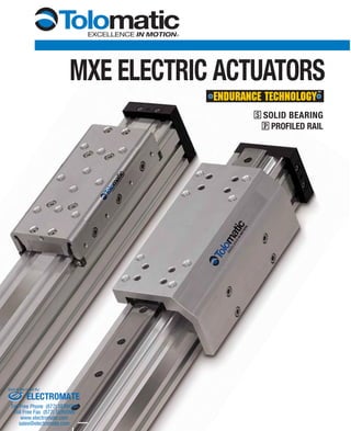
  • 1. MXE ELECTRIC ACTUATORS MAXIMUM DURABILITYMAXIMUM DURABILITY S SOLID BEARING P PROFILED RAIL ELECTROMATE Toll Free Phone (877) SERVO98 Toll Free Fax (877) SERV099 www.electromate.com sales@electromate.com Sold & Serviced By:
  • 2. 2 1.800.328.21742 1.800.328.21742 1.800.328.2174 S-SOLID BEARING •Large bearing surface contact area optimizes stress distribution on bearing for long service life •Large carrier mounting pattern for more load stability and compatibility with existing BCS applications •Engineered bearing material does not require additional lubrication • Solid bearings are field replaceable P-PROFILED RAIL •THK® Caged Ball® bearings with reduced friction for reliable service life •High load and bending moment capacities •Low profile to fit your application •High precision bearings feature smooth, low breakaway motion The MXE electric actuator is exactly what you expect from the industry’s number one rodless supplier. Designed with our exclusive ENDURANCE TECHNOLOGYSM features, the MX delivers superior per- formance to meet the most demanding applications. Nobody knows rodless like Tolomatic, and the MX proves it. THE MXE ELECTRIC ACTUATOR – DESIGNED TO OUTLAST EVERY RODLESS ACTUATOR ON THE MARKET • DURABLE BEARINGS. Two bearing choices to match your application needs. Solid bearing design optimizes stress distribution for optimal performance. Profiled rail design uses THK® Caged Ball® technology to reduce friction and extend actuator life. • DURABLE BANDS. Stainless steel bands are stronger and will not elongate like elastomer (non-metallic) bands, providing a reliable seal over the life of the actuator. Choose from our broad line of MX products: MXP pneumatic rodless cylinders and MXE electric actuators. World class product performance, five days built-to-order and legendary customer service . . . what you expect from the leader . . . Tolomatic! ELECTROMATE Toll Free Phone (877) SERVO98 Toll Free Fax (877) SERV099 www.electromate.com sales@electromate.com Sold & Serviced By:
  • 3. www.tolomatic.com/mxe 3www.tolomatic.com/mxe 3 SELECT THE PERFORMANCE YOU NEED MOMENT & LOAD CAPACITY COMPARISON Bearing Type Solid Bearing Profiled Rail Moment Moderate High Capacity + Mx Capacity Ideal • Side Loads • High Moment Loads Applications • Moderate or Light • High Speeds with Loads Heavy Loads • Guided Loads • High Precision Product Features Page 4 Page 6 Tolomatic MX Electric Actuator Model Graph for model comparison, data from MXE40 actuator Choose from: • Two Bearing Models • Six Actuator Sizes • Built to Your Specified Stroke Length 0 1,000 2,000 PS MAX.BENDINGMOMENT(in.-lbs.) 1,800 1,600 1,400 1,200 800 600 400 200 224 Nm 112 Nm MAX.Fz[LOAD](lbs.)MAX.Fz[LOAD](lbs.) 225 736 FzMx Fz MyMy Mz Mx My Mz Fz TABLE OF CONTENTS Introduction..........................................2 Comparison..........................................3 S Solid Bearing Features......................4 P Profiled Rail Features........................6 Motion Control Systems Overview........8 S Moment and Load Capacity...........10 P Moment and Load Capacity...........11 Specifications.....................................12 Tube Clamp Reqirements...................15 Screw Critical Speed Capacities.........16 S Solid Bearing Dimensions...............26 P Profiled Rail Bearing Dimensions....28 Inline Motor Mounting Dimensions......30 S Reverse Parallel Motor Mounting Dimensions.........................................34 P Reverse Parallel Motor Mounting Dimensions.........................................39 Switches ............................................44 S Adjustment Procedures..................47 Compile Application Requirements.....48 Selection Guidelines...........................49 Service Parts......................................50 Ordering.............................................51
  • 4. 4 1.800.328.21744 1.800.328.21744 1.800.328.21744 1.800.328.21744 1.800.328.21744 1.800.328.21744 1.800.328.2174 S SOLID BEARING Endurance Technology features are designed for maximum durability to provide extended service life. DUST WIPER •Formed end cap and side dust wipers keep contaminants from entering the actuator’s internal area RETAINED DUST BAND •Retained dust band keeps contaminants from entering the actuator interior, protecting components for reduced maintenance and increased uptime LARGE FLEXIBLE MOUNTING PATTERN •Carrier gives more load stability •Compatibility with existing BCS applications •More fastening options STAINLESS STEEL BAND •Exterior dust band made of fatigue resistant stainless steel STAINLESS STEEL IS DURABLE, FLEXIBLE AND CORROSION RESISTANT NON-WEAR BAND RETENTION •Magnetically retained band is not subject to wear as are mechanically retained systems MULTIPLE SCREW TECHNOLOGIES YOU CAN CHOOSE: •Solid nuts of engineered resins for quiet performance at the lowest cost - 5 choices •Ball nuts offer positioning accuracy and repeatability with longer life, low-backlash available - 3 choices ELECTROMATE Toll Free Phone (877) SERVO98 Toll Free Fax (877) SERV099 www.electromate.com sales@electromate.com Sold & Serviced By:
  • 5. www.tolomatic.com/mxe 5www.tolomatic.com/mxe 5www.tolomatic.com/mxe 5www.tolomatic.com/mxe 5www.tolomatic.com/mxe 5www.tolomatic.com/mxe 5 …MAXIMUM DURABILITY OPTIONS AUXILIARY CARRIER DC • 2X higher Fz (load) capacity • High bending moment capacity FLOATING MOUNT FL •Compensates for non-parallelism between MX actuator and externally guided load TUBE CLAMPS TC •Used for intermediate support •Flush with bottom of actuator to retain low profile •Drop-in, adjustable mounting locations (MXE16 uses T-nuts with mounting plates) MOUNTING PLATES MP •To provide clearance for motor and mount •Use in conjunction with tube clamps SWITCHES •Wide variety of sensing choices: Reed, Solid State PNP or NPN, all available normally open or normally closed •Flush mount, drop-in installation •Bright LEDs, power & signal indication •CE rated, RoHS compliant NOTE: Boxed letters indicate ordering codes TRAPEZOIDAL BEARINGS •Trapezoidal design maximizes bearing surface area for less pressure on bearing surfaces; less pressure results in less wear •Engineered bearing material has low static and dynamic friction with low wear properties for long lasting, smooth operation •Bearings are field replaceable for extended service life INCH OR METRIC MOUNTING •Your choice of inch (US standard) or metric mounting to the carrier NON-BINDING BEARING ARMS •Bearings are tensioned indirectly, providing bind free adjustment YOUR MOTOR HERE YOU CAN CHOOSE: •Motor or gearbox supplied and installed by Tolomatic •Specify the device to be installed and actuator ships with proper mounting hardware - MXE is a “Your Motor Here” actuator for easy in-line motor installation. Check our website (www.tolomatic.com/ymh) for complete YMH information •Specify and ship your device to Tolomatic for factory installation MOTOR ORIENTATION YOU CAN CHOOSE: •In-line option directly couples the driving shaft and is a one-piece housing construction for optimum alignment and support of the motor •Reverse-parallel option minimizes the overall length and offers a 1:1 or 2:1 belt ratio INTERNAL MAGNETS •Standard feature that allows sensor installation on the open side or bottom of the extrusion ELECTROMATE Toll Free Phone (877) SERVO98 Toll Free Fax (877) SERV099 www.electromate.com sales@electromate.com Sold & Serviced By:
  • 6. 6 1.800.328.21746 1.800.328.21746 1.800.328.21746 1.800.328.21746 1.800.328.2174 P PROFILED RAIL Endurance Technology features are designed for maximum durability to provide extended service life. INTERNAL MAGNETS •Standard feature that allows sensor installation on the open side or bottom of the extrusion INCH OR METRIC MOUNTING •Your choice of inch (US standard) or metric mounting to the carrier CAGED BALL® BEARINGS •THK® Caged Ball® bearings are used to reduce friction and extend actuator life •Caged Ball® technology creates a grease pocket between ball elements, reducing friction, noise and maintenance •Large permissible moment loads •High speed operation, low heat generation •High precision, smooth, low friction motion DUST WIPER •Formed end cap and side dust wipers keep contaminants from entering the actuator’s internal area STAINLESS STEEL BAND •Exterior dust band made of fatigue resistant stainless steel STAINLESS STEEL IS DURABLE, FLEXIBLE AND CORROSION RESISTANT ELECTROMATE Toll Free Phone (877) SERVO98 Toll Free Fax (877) SERV099 www.electromate.com sales@electromate.com Sold & Serviced By:
  • 7. www.tolomatic.com/mxe 7www.tolomatic.com/mxe 7www.tolomatic.com/mxe 7www.tolomatic.com/mxe 7 …MAXIMUM DURABILITY OPTIONS AUXILIARY CARRIER DC • 2X higher Fz (load) capacity • High bending moment capacity TUBE CLAMPS TC •Used for intermediate support •Flush with bottom of actuator to retain low profile •Drop-in, adjustable mounting locations (MXE16 uses T-nuts with Mounting Plates) MOUNTING PLATES MP •To provide clearance for motor and mount •Use in conjunction with tube clamps SWITCHES •Wide variety of sensing choices: Reed, Solid State PNP or NPN, all available normally open or normally closed •Flush mount, drop-in installation •Bright LEDs, power & signal indication •CE rated, RoHS compliant NOTE: Boxed letters indicate ordering codes NON-WEAR BAND RETENTION •Magnetically retained band is not subject to wear as are mechanically retained systems •Immediate band engagement and release results in less drag on carrier for lower friction force during initial carrier movement LOW CARRIER HEIGHT •Reduces overall actuator envelope •Large mounting pattern for high load stability YOUR MOTOR HERE YOU CAN CHOOSE: •Motor or gearbox supplied and installed by Tolomatic •Specify the device to be installed and actuator ships with proper mounting hardware - MXE is a “Your Motor Here” actuator for easy in-line motor installation. Check our website (www.tolomatic.com/ ymh) for complete YMH information •Specify and ship your device to Tolomatic for factory installation MOTOR ORIENTATION YOU CAN CHOOSE: •In-line option directly couples the driving shaft and is a one-piece housing construction for optimum alignment and support of the motor •Reverse-parallel option minimizes the overall length and offers a 1:1 or 2:1 belt ratio MULTIPLE SCREW TECHNOLOGIES YOU CAN CHOOSE: •Solid nuts of engineered resins offer quiet performance at the lowest cost - 5 choices •Ball nuts offer positioning accuracy and repeatability with longer life, low-backlash available - 3 choices RETAINED DUST BAND •Retained dust band keeps contaminants from entering the actuator interior, protecting components for reduced maintenance and increased uptime ELECTROMATE Toll Free Phone (877) SERVO98 Toll Free Fax (877) SERV099 www.electromate.com sales@electromate.com Sold & Serviced By:
  • 8. 8 1.800.328.21748 1.800.328.21748 1.800.328.2174 HUB MULTI-AXIS MOTION HUB WITH I/O BOB BREAK OUT BOARD MRS STEPPER SYSTEM STEPPER MOTORS NEMA 23-Frame and 34-Frame MRS Stepper Motors STEPPER DRIVE AND CONTROLLER The DS [STAC6-S] & SI [STAC6-Si] represent the latest developments in stepper drive technology, incorporating features that derive the highest performance from today’s stepper motors. Anti-resonance and waveform damping control algorithms provide excellent performance. • Current Output 0.5 to 6.0 A • 90-135 VAC Input • 167V Bus • Set-up and configuration software • Configurable idle current reduction • External control options • Pulse and direction • Analog command signal • Host command via RS232/485 • Integral control options - Si ProgrammerTM - intuitive easy-to-use graphical programming language •Designed for increased torque and acceleration rates over a wider speed range •Standard NEMA frame sizes (23 and 34) MMI OPERATOR INTERFACE • Networks Stepper products for multi-axis motion applications. STEPPER ACCESSORIES • Connects the I/O points of the DS [STAC6-S] & SI [STAC6-Si] • Allows visual setup of the panel to show a particular action taking place, or to prompt the user to make a decision or provide information such as move distance, move speed, repeat count. • Speeds up to 3,000 RPM • High resolution (up to 51,200 steps per rev) • Holding torque to 1845 oz-in (13.03 Nm) • 2000 line Quadrature encoder option • 10 ft. power cables with connector pre-wired DS [ ] SI [ ] ! ! • ANTI-RESONANCE Achieves higher speeds and better torque utilization ! Please note the Tolomatic ordering codes. Use these codes when ordering stepper components from Tolomatic (Applied Motion Products model equivalents appear in [brackets]) • COMMAND SIGNAL SMOOTHING Soften effect of changes in velocity and direction • MICROSTEP EMULATION Smooth, high resolution motion across range of speeds • TORQUE RIPPLE SMOOTHING Adjusts current waveform to reduce low speed torque ripple, providing smoother motion at low speeds • SELF TEST Measure motor parameters automatically to optimize system performance ADD YOUR MOTION CONTROL SYSTEM TO THE MXE or INDUSTRY STANDARD MOUNTING HYBRID MOTOR DESIGN LATEST IN MICROSTEPPING TECHNOLOGY
  • 9. www.tolomatic.com/mxe 9www.tolomatic.com/mxe 9 MRV SERVO SYSTEM DIGITAL SERVO DRIVE AND CONTROLLER Designed by Tolomatic, the Axiom+ PV combines the functions of a servo drive, motion controller and programmable logic controller in a single package. Our all- in-one design eliminates the confusion of multiple software packages, removes discrete wiring or network programming between controllers, and simplifies application programming. The free Windows® -based software package programs the PLC functions in a standard ladder logic environment and the motion control functions in a simple graphical motion editor. SERVO MOTORS The MRV series of brushless servo motors is available in a wide range of torque outputs to meet your demanding applications. These motors are designed for precision motion profiles, low inertia, maximum power density and long continuous life. SPECIFICATIONS: TORQUE Max. Rotor Cont. Peak Speed Inertia (lb-in) (lb-in) (RPM) (lb-in2 ) MRV11 3 12 5000 0.02 MRV21 4 11 6000 0.05 MRV22 8 22 6000 0.10 MRV23 11 33 6000 0.14 MRV24 15 47 6000 0.19 MRV31 17 85 6000 0.38 MRV32 30 150 6000 0.69 MRV33 44 220 6000 1.00 MRV51 80 240 3000 2.53 SPECIFICATIONS: PV10 PV20 PV30 Input Line 95 - 250 VAC, 1Ø or 3Ø Input Hz 47 - 63 Hz Output Current Peak (Apeak) 10 20 30 Output Current Cont (Acont) 5 10 15 Output Power Cont (kW) 1.4 2.8 4.2 Discrete Inputs 15, optically isolated 5-25VDC Discrete Outputs 8, optically isolated 5-25VDC Analog Inputs 1, 14-bit Differential ±10VDC •1000 line quadrature industry standard incremental encoder feedback •Standard NEMA frame sizes (17, 23, 34 and 56) •Thermistor provides over temperature protection •IP65 rated SELECT A COMPLETE SYSTEM FROM TOLOMATIC • FLUX VECTOR CURRENT CONTROL Provides closed loop motor control of torque producing current by sensing motor current in each individual motor phase. This gives a high bandwidth torque response over the full speed range with high efficiency and minimal phase lag • PLUGGABLE SCREW TERMINAL BLOCKS Allows easier termination, quick connection or removal of wiring and direct access to signals for testing with a meter • MODBUS RTU COMMUNICATIONS Standard Modbus RTU is built into the drive for communications to other controllers or operator interfaces • AMPLIFIER ONLY OPTION The DV version is for use with an external controller that provides analog velocity, analog torque or step commands HIGH RESOLUTION ENCODER INDUSTRY STANDARD MOUNTING INTEGRAL PROTECTION INNOVATIVE SERVO TECHNOLOGY ELECTROMATE Toll Free Phone (877) SERVO98 Toll Free Fax (877) SERV099 www.electromate.com sales@electromate.com Sold & Serviced By:
  • 10. 10 1.800.328.217410 1.800.328.217410 1.800.328.2174 The above ratings are the maximum values for shock-free, vibration- free operation in a typical industrial environment, which must not be exceeded even in dynamic operation. Contact Tolomatic for assistance in selecting the most appropriate actuator for your application. = Mxmax LF Mx + Mymax My + Mzmax Mz + Fymax Fy + < 1 Fzmax Fz With combined loads, LF must not exceed the value 1. Ratings were calculated with the following conditions: 1.) Coupling between carriers is rigid. 2.) Load is equally distributed between carriers. STANDARD CARRIER S SOLID BEARING MOMENT AND LOAD CAPACITY *At minimum “D” distance see graph below for complete information DC AUXILIARY CARRIER 3.) Coupling device applies no misalignment loads to carriers. AUXILIARY CARRIER BENDING MOMENTS WITH INCREASED “D” DISTANCE BETWEEN CARRIERS “D”DISTANCE BETWEEN CARRIERS “D”DISTANCE BETWEEN CARRIERS SIZE MAXIMUM BENDING MOMENTS MAX. LOAD Mx My Mz Fz in-lbs N-m in-lbs N-m in-lbs N-m lbf N 16 22 2.5 19 2.1 25 2.8 35 156 25 60 6.8 110 12.4 34 3.8 70 311 32 100 11.3 350 39.5 140 15.8 150 667 40 275 31.1 600 67.8 220 24.9 225 1,001 50 315 35.6 1,155 131.0 341 38.5 315 1,401 63 585 66.1 2,340 264.0 520 58.8 520 2,313 SIZE “D” MINIMUM MAXIMUM BENDING MOMENTS* MAX. LOAD Mxa Mya Mza Fza in mm in-lbs N-m in-lbs N-m in-lbs N-m lbf N 16 5.0 127 44 5.0 175 19.8 175 19.8 70 311 25 6.0 152 120 13.6 420 47.5 420 47.5 140 623 32 7.0 178 200 22.6 1,050 119.0 1,050 119.0 300 1,334 40 8.5 216 550 62.1 1,913 216.0 1,913 216.0 450 2,002 50 8.6 218 630 71.2 2,709 306.0 2,709 306.0 630 2,802 63 13.0 330 1,170 132.0 6,760 764.0 6,760 764.0 1,040 4,626 30 25 20 15 10 5 700 600 500 400 300 200 0 2,500 2500 500 750 1,000 1,250 1,500 1,750 5,000 7,500 10,000 Mya & Mza MOMENT (in-lbs) Mya & Mza MOMENT (N-m) DISTANCEBETWEEN CARRIERS(in) DISTANCEBETWEEN CARRIERS(mm) 12,500 15,000 16 25 32 40 16 25 32 40 5050 6363 ELECTROMATE Toll Free Phone (877) SERVO98 Toll Free Fax (877) SERV099 www.electromate.com sales@electromate.com Sold & Serviced By:
  • 11. www.tolomatic.com/mxe 11www.tolomatic.com/mxe 11 STANDARD CARRIER *At minimum “D” distance see below for complete information P PROFILED RAIL MOMENT AND LOAD CAPACITY DC AUXILIARY CARRIER The above ratings are the maximum values for shock-free, vibration- free operation in a typical industrial environment, which must not be exceeded even in dynamic operation. Contact Tolomatic for assistance in selecting the most appropriate actuator for your application. = Mxmax LF Mx + Mymax My + Mzmax Mz + Fymax Fy + < 1 Fzmax Fz With combined loads, LF must not exceed the value 1. Ratings were calculated with the following conditions: 1.) Coupling between carriers is rigid. 2.) Load is equally distributed between carriers. 3.) Coupling device applies no misalignment loads to carriers. AUXILIARY CARRIER BENDING MOMENTS WITH INCREASED “D” DISTANCE BETWEEN CARRIERS “D”DISTANCE BETWEEN CARRIERS “D”DISTANCE BETWEEN CARRIERS SIZE MAXIMUM BENDING MOMENTS MAXIMUM LOAD Mx My Mz Fy Fz in-lbs N-m in-lbs N-m in-lbs N-m lbf N lbf N 16 39 4.5 339 38.3 339 38.3 217 966 217 966 25 126 14.3 502 56.7 377 42.6 449 1,996 449 1,996 32 226 25.6 1,344 152.0 1,344 152.0 569 2,531 569 2,531 40 604 68.2 1,913 216.0 1,913 216.0 736 3,274 736 3,274 50 811 91.7 3,483 394.0 3,483 394.0 1,014 4,510 1,014 4,510 63 1,019 115.0 5,339 603.0 5,339 603.0 1,292 5,745 1,292 5,745 Mating surface of mounted component must maintain a flatness of at least .0015" [0.040mm] SIZE “D” MINIMUM MAXIMUM BENDING MOMENTS* MAXIMUM LOAD Mxa Mya Mza Fya Fza in mm in-lbs N-m in-lbs N-m in-lbs N-m lbf N lbf N 16 5.0 127 79 8.9 620 70.0 620 70.0 434 1,932 434 1,932 25 6.0 152 252 28.5 1,610 182 1,610 182 898 3,993 898 3,993 32 7.0 178 453 51.1 2,202 249 2,202 249 1,138 5,063 1,138 5,063 40 8.5 216 1,208 136.0 3,601 407 3,601 407 1,472 6,549 1,472 6,549 50 8.6 218 1,623 183.0 4,966 561 4,966 561 2,028 9,020 2,028 9,020 63 13.0 330 2,038 230.0 9,508 1,074 9,508 1,074 2,583 11,490 2,583 11,490 30 25 20 15 10 5 700 600 500 400 300 200 0 10,0005,000 1,0000 2,000 3,000500 1,500 2,500 20,000 25,00015,000 30,000 Mya & Mza MOMENT (in-lbs) Mya & Mza MOMENT (N-m) DISTANCEBETWEEN CARRIERS(in) DISTANCEBETWEEN CARRIERS(mm) 16 25 3232 40 5050 16 25 40 6363 ELECTROMATE Toll Free Phone (877) SERVO98 Toll Free Fax (877) SERV099 www.electromate.com sales@electromate.com Sold & Serviced By:
  • 12. IP Rating - 44 Approximately equivalent to the requirements of IP44 (protected against ingress of solid particles greater than .039 in (1 mm) and splashing water) 12 1.800.328.217412 1.800.328.217412 1.800.328.2174 ACTUATOR SERIES SCREW DIAMETER SCREW TYPE SCREW PITCH BREAKAWAY TORQUE SINGLE CARRIER AUXILIARY CARRIER in mm rev/in oz-in N-m oz-in N-m MXE16 0.250 6.35 SN 02 10 0.071 14 0.099 0.250 6.35 SN 04 10 0.071 14 0.099 0.250 6.35 SN 16 10 0.071 14 0.099 MXE25 0.375 9.53 BN 08 16 0.113 18 0.127 0.375 9.53 BNL 08 16 0.113 18 0.127 0.500 12.70 SN 01 30 0.212 46 0.325 0.500 12.70 SN 02 25 0.177 35 0.247 0.500 12.70 SN 05 18 0.127 22 0.155 MXE32 0.375 9.53 BN 08 16 0.113 18 0.127 0.375 9.53 BNL 08 16 0.113 18 0.127 0.500 12.70 SN 01 30 0.212 46 0.325 0.500 12.70 SN 02 25 0.177 35 0.247 0.500 12.70 SN 05 18 0.127 22 0.155 MXE40 0.500 12.70 BN 02 28 0.198 35 0.247 0.500 12.70 BNL 02 28 0.198 35 0.247 0.625 15.88 BN 05 35 0.247 45 0.318 0.625 15.88 BNL 05 35 0.247 45 0.318 0.625 15.88 SN 02 35 0.245 44 0.311 0.750 19.05 SN 01 50 0.353 72 0.508 MXE50 0.750 19.05 BN 02 40 0.282 50 0.353 0.750 19.05 BNL 02 40 0.282 50 0.353 0.750 19.05 BN 05 35 0.247 45 0.318 0.750 19.05 BNL 05 35 0.247 45 0.318 0.750 19.05 SN 01 50 0.353 72 0.508 0.750 19.05 SN 02 35 0.247 44 0.311 MXE63 1.000 25.40 BN 01 75 0.530 107 0.756 1.000 25.40 BNL 01 75 0.530 107 0.756 1.000 25.40 BN 02 75 0.530 107 0.756 1.000 25.40 BNL 02 75 0.530 107 0.756 1.000 25.40 BN 04 85 0.600 121 0.855 1.000 25.40 BNL 04 85 0.600 121 0.855 1.000 25.40 SN 04 75 0.530 107 0.756 BREAKAWAY TORQUEFRICTION FORCE S-ACTUATORS 350 300 250 200 150 100 50 0 1500 1250 1000 750 500 250 0 0 5 10 15 20 25 30 35 40 45 0 25 50 75 100 125 150 175 200 FRICTION FORCE (lbf) FRICTION FORCE (N) LOADWEIGHT(lbf) LOADWEIGHT(N) 32 5050 25 40 32 25 40 6363 1616 S & P ACTUATOR SPECIFICATIONS AND BREAKAWAY TORQUE CARRIER WEIGHT (including nut bracket assembly) BASE ACTUATOR WEIGHT (excluding nut bracket and carrier assembly) WEIGHT PER UNIT OF STROKE STRAIGHTNESS / FLATNESS* TEMPERATURE RANGE ACTUATOR SERIES S SOLID P PROFILED S SOLID P PROFILED S SOLID P PROFILED lb kg lb kg lb kg lb kg lb/in kg/mm lb/in kg/mm in mm °F °C MXE16 0.47 0.21 0.58 0.26 1.24 0.56 1.43 0.65 0.10 0.0018 0.12 0.0021 .00067 x L† .0170 x L† 40 to 130 4 to 54 MXE25 0.91 0.41 1.02 0.46 2.11 0.96 2.44 1.11 0.19 0.0034 0.25 0.0045 MXE32 1.74 0.79 2.12 0.96 2.74 1.24 3.30 1.50 0.29 0.0052 0.37 0.0066 MXE40 3.15 1.43 3.72 1.69 5.34 2.42 6.88 3.12 0.40 0.0071 0.58 0.0104 MXE50 5.27 2.39 6.97 3.16 14.91 6.76 18.27 8.29 0.64 0.0114 0.84 0.0150 MXE63 12.96 5.88 25.54 11.58 35.05 15.90 39.34 17.84 1.08 0.0193 1.36 0.0243 GENERAL ACTUATOR SPECIFICATIONS *Actuator mounted on a flat surface and fully restrained (See tube clamp graphs page 15) † L = Maximum distance between supports ELECTROMATE Toll Free Phone (877) SERVO98 Toll Free Fax (877) SERV099 www.electromate.com sales@electromate.com Sold & Serviced By:
  • 13. www.tolomatic.com/mxe 13www.tolomatic.com/mxe 13 S & P SPECIFICATIONS ACTUATOR SERIES SCREW DIAMETER SCREW TYPE SCREW PITCH SCREW LEAD LEAD ACCURACY BACKLASH MAX THRUST MAX STROKE in mm rev/in in mm in/ft mm/300mm in mm lb N in mm MXE16 0.250 6.35 SN 02 0.50 12.70 0.005 0.13 0.015 0.38 45 200 29 737 0.250 6.35 SN 04 0.25 6.35 0.005 0.13 0.015 0.38 45 200 29 737 0.250 6.35 SN 16 0.06 1.59 0.005 0.13 0.015 0.38 45 200 29 737 MXE25 0.375 9.53 BN 08 0.13 3.18 0.004 0.10 0.015 0.38 130 578 61 1549 0.375 9.53 BNL 08 0.13 3.18 0.004 0.10 0.002 0.05 130 578 61 1549 0.500 12.70 SN 01 1.00 25.40 0.006 0.15 0.007 0.18 170 756 85 2159 0.500 12.70 SN 02 0.50 12.70 0.005 0.13 0.007 0.18 170 756 120 3048 0.500 12.70 SN 05 0.20 5.08 0.006 0.15 0.007 0.18 170 756 120 3048 MXE32 0.375 9.53 BN 08 0.13 3.18 0.004 0.10 0.015 0.38 130 578 61 1549 0.375 9.53 BNL 08 0.13 3.18 0.004 0.10 0.002 0.05 130 578 61 1549 0.500 12.70 SN 01 1.00 25.40 0.006 0.15 0.007 0.18 170 756 85 2159 0.500 12.70 SN 02 0.50 12.70 0.005 0.13 0.007 0.18 170 756 120 3048 0.500 12.70 SN 05 0.20 5.08 0.006 0.15 0.007 0.18 170 756 120 3048 MXE40 0.500 12.70 BN 02 0.50 12.70 0.003 0.08 0.015 0.38 800 3559 59 1499 0.500 12.70 BNL 02 0.50 12.70 0.003 0.08 0.002 0.05 800 3559 59 1499 0.625 15.88 BN 05 0.20 5.08 0.003 0.08 0.015 0.38 800 3559 59 1499 0.625 15.88 BNL 05 0.20 5.08 0.003 0.08 0.002 0.05 800 3559 59 1499 0.625 15.88 SN 02 0.50 12.70 0.005 0.13 0.007 0.18 200 890 120 3048 0.750 19.05 SN 01 1.00 25.40 0.005 0.13 0.007 0.18 300 1334 120 3048 MXE50 0.750 19.05 BN 02 0.50 12.70 0.004 0.10 0.015 0.38 2700 12010 120 3048 0.750 19.05 BNL 02 0.50 12.70 0.004 0.10 0.002 0.05 2700 12010 120 3048 0.750 19.05 BN 05 0.20 5.08 0.003 0.08 0.015 0.38 950 4226 120 3048 0.750 19.05 BNL 05 0.20 5.08 0.003 0.08 0.002 0.05 950 4226 120 3048 0.750 19.05 SN 02 0.50 12.70 0.005 0.13 0.007 0.18 300 1335 120 3048 0.750 19.05 SN 01 1.00 25.40 0.005 0.13 0.007 0.18 300 1335 120 3048 MXE63 1.000 25.40 BN 01 1.00 25.40 0.004 0.10 0.015 0.38 2500 11121 103 2616 1.000 25.40 BNL 01 1.00 25.40 0.004 0.10 0.002 0.05 2500 11121 103 2616 1.000 25.40 BN 02 0.50 12.70 0.004 0.10 0.015 0.38 4300 19127 103 2616 1.000 25.40 BNL 02 0.50 12.70 0.004 0.10 0.002 0.05 4300 19127 103 2616 1.000 25.40 BN 04 0.25 6.35 0.004 0.10 0.015 0.38 3300 14679 103 2616 1.000 25.40 BNL 04 0.25 6.35 0.004 0.10 0.002 0.05 3300 14679 103 2616 1.000 25.40 SN 04 0.25 6.35 0.010 0.25 0.007 0.18 400 1779 103 2616 SCREW SPECIFICATIONS ELECTROMATE Toll Free Phone (877) SERVO98 Toll Free Fax (877) SERV099 www.electromate.com sales@electromate.com Sold & Serviced By:
  • 14. 14 1.800.328.217414 1.800.328.217414 1.800.328.2174 S & P SPECIFICATIONS REFLECTED INERTIA ACTUATOR SERIES SCREW DIAMETER SCREW TYPE SCREW PITCH REFLECTED INERTIA BASE ACTUATOR PER IN OF STROKE S SOLID P PROFILED RAIL IN-LINE REV PARALLEL IN-LINE REV PARALLEL in mm rev/in lb-in2 kg-cm2 lb-in2 kg-cm2 lb-in2 kg-cm2 lb-in2 kg-cm2 lb-in2 kg-cm2 MXE16 0.250 6.35 SN 02 0.0058 0.0170 0.0058 0.0170 0.0069 0.0202 0.0069 0.0202 0.0001 0.0003 0.250 6.35 SN 04 0.0020 0.0059 0.0020 0.0059 0.0023 0.0067 0.0023 0.0067 0.0001 0.0003 0.250 6.35 SN 16 0.0009 0.0026 0.0009 0.0026 0.0009 0.0026 0.0009 0.0026 0.0001 0.0003 MXE25 0.375 9.53 BN 08 0.0062 0.0182 0.0062 0.0182 0.0063 0.0183 0.0063 0.0183 0.0005 0.0015 0.375 9.53 BNL 08 0.0062 0.0182 0.0062 0.018 0.0063 0.0183 0.0063 0.0183 0.0005 0.0015 0.500 12.70 SN 01 0.0498 0.1456 0.0498 0.1456 0.0541 0.1583 0.0541 0.1583 0.0017 0.0050 0.500 12.70 SN 02 0.0213 0.0623 0.0213 0.0623 0.0224 0.0654 0.0224 0.0654 0.0017 0.0050 0.500 12.70 SN 05 0.0133 0.0390 0.0133 0.0390 0.0135 0.0395 0.0135 0.0395 0.0017 0.0050 MXE32 0.375 9.53 BN 08 0.0066 0.0193 0.0066 0.0193 0.0068 0.0198 0.0068 0.0198 0.0005 0.0015 0.375 9.53 BNL 08 0.0066 0.0193 0.0066 0.0193 0.0068 0.0198 0.0068 0.0198 0.0005 0.0015 0.500 12.70 SN 01 0.0832 0.2436 0.0842 0.2465 0.1005 0.2940 0.1015 0.2969 0.0017 0.0050 0.500 12.70 SN 02 0.0296 0.0868 0.0306 0.0897 0.0340 0.0994 0.0350 0.1023 0.0017 0.0050 0.500 12.70 SN 05 0.0147 0.0429 0.0157 0.0458 0.0153 0.0449 0.0163 0.0478 0.0017 0.0050 MXE40 0.500 12.70 BN 02 0.0502 0.1468 0.0502 0.1470 0.0544 0.1593 0.0545 0.1594 0.0017 0.0050 0.500 12.70 BNL 02 0.0502 0.1480 0.0512 0.1497 0.0544 0.1593 0.0545 0.1594 0.0017 0.050 0.625 15.88 BN 05 0.0506 0.1480 0.0512 0.1497 0.0512 0.1500 0.0518 0.1517 0.0042 0.0123 0.625 15.88 BNL 05 0.0506 0.1480 0.0512 0.1497 0.0512 0.1500 0.0518 0.1517 0.0042 0.0123 0.625 15.88 SN 02 0.0781 0.2286 0.0787 0.2304 0.0842 0.2463 0.0848 0.2480 0.0042 0.0123 0.750 19.05 SN 01 0.2035 0.5956 0.2041 0.5973 0.2276 0.6661 0.2282 0.6679 0.0087 0.0255 MXE50 0.750 19.05 BN 02 0.1438 0.4208 0.1451 0.4246 0.1565 0.4580 0.1578 0.4618 0.0087 0.0255 0.750 19.05 BNL 02 0.1438 0.4208 0.1451 0.4246 0.1565 0.4580 0.1578 0.4618 0.0087 0.0255 0.750 19.05 BN 05 0.1104 0.3231 0.1117 0.3269 0.1124 0.3289 0.1137 0.3327 0.0087 0.0255 0.750 19.05 BNL 05 0.1104 0.3231 0.1117 0.3269 0.1124 0.3289 0.1137 0.3327 0.0087 0.0255 0.750 19.05 SN 02 0.1528 0.4472 0.1541 0.4510 0.1708 0.4998 0.1721 0.5036 0.0087 0.0255 0.750 19.05 SN 01 0.2969 0.8689 0.2982 0.8727 0.3688 1.0793 0.3701 1.0831 0.0087 0.0255 MXE63 1.000 25.40 BN 01 0.8865 2.5943 0.8873 2.5966 1.2629 3.6958 1.2637 3.6981 0.0275 0.0805 1.000 25.40 BNL 01 0.8865 2.5943 0.8873 2.5966 1.2629 3.6958 1.2637 3.6981 0.0275 0.0805 1.000 25.40 BN 02 0.5966 1.7459 0.5974 1.7482 0.6907 2.0213 0.6915 2.0236 0.0275 0.0805 1.000 25.40 BNL 02 0.5966 1.7459 0.5974 1.7482 0.6907 2.0213 0.6915 2.0236 0.0275 0.0805 1.000 25.40 BN 04 0.5245 1.5349 0.5253 1.5372 0.5480 1.6037 0.5488 1.6060 0.0275 0.0805 1.000 25.40 BNL 04 0.5245 1.5349 0.5253 1.5372 0.5480 1.6037 0.5488 1.6060 0.0275 0.0805 1.000 25.40 SN 04 0.5319 1.5566 0.5327 1.5589 0.5652 1.6540 0.5660 1.6563 0.0275 0.0805 ELECTROMATE Toll Free Phone (877) SERVO98 Toll Free Fax (877) SERV099 www.electromate.com sales@electromate.com Sold & Serviced By:
  • 15. www.tolomatic.com/mxe 15www.tolomatic.com/mxe 15 S SOLID BEARING P PROFILED RAIL BEARING S & P TUBE CLAMP REQUIREMENTS 0 5 10 15 20 25 30 35 40 45 50 55 60 65 70 0 200 400 600 800 1,000 1,200 1,400 1,600 1,800 1 2 4 6 8 20 40 60 80 200 2,000 400 600 800 10 100 1,000 10 100 1,000 10,000 MAX DISTANCE BETWEEN CLAMPS (in) "L" FORCEONCARRIER(N) FORCEONCARRIER(lbf) MAX DISTANCE BETWEEN CLAMPS (mm) "L" 16 25 32 40 5050 63 16 25 32 40 63 217 LBF MAX 449 LBF MAX 569 LBF MAX 736 LBF MAX 1,014 LBF MAX 1,292 LBF MAX 217 LBF MAX 449 LBF MAX 569 LBF MAX 736 LBF MAX 1,014 LBF MAX 1,292 LBF MAX 1 2 4 6 8 20 200 40 60 80 10 100 0 10 20 30 40 50 60 70 10 100 1,000 0 200 400 600 800 1,000 1,200 1,400 1,600 1,800 400 600 16 25 32 40 5050 63 16 25 32 40 63 150 LBF MAX 225 LBF MAX 315 LBF MAX315 LBF MAX 520 LBF MAX 70 LBF MAX 35 LBF MAX 150 LBF MAX 225 LBF MAX 520 LBF MAX 70 LBF MAX 35 LBF MAX MAX DISTANCE BETWEEN CLAMPS (in) "L" FORCEONCARRIER(N) FORCEONCARRIER(lbf) MAX DISTANCE BETWEEN CLAMPS (mm) "L" L L L L NOTE: MXE16 uses T-Nuts with mounting plates NOTE: MXE16 uses T-Nuts with mounting plates
  • 16. 16 1.800.328.217416 1.800.328.217416 1.800.328.2174 SCREW CRITICAL SPEED CAPACITIES 3048 0 20 40 60 80 100 STROKE (in) SPEED(in/sec) 1 10 8829 120 35 30 60 SPEED(mm/sec) 0.4 0.6 0.8 8 6 5 4 2 40 20 TPI MAX. NUT / (turns THRUST MODEL SCREW per in) (lbf) MXE63 SN04 4 400 MXE50 SNO2 2 300 MXE50 & 40 SNO1 2 300 MXE40 SNO2 2 200 MXE32 & 25 SN01 1 170 MXE32 & 25 SN02 2 170 MXE32 & 25 SN05 5 170 MXE16 SN02 2 45 MXE16 SN04 4 45 MXE16 SN16 16 45 MXE16SN02MXE16SN04 MXE16SN16 MXE50&40 SN01 MXE50 SN02 MXE40 SN02 MXE32&25 SN02 MXE32&25SN01 MXE32&25 SN05 MXE63 SN04 200 400 600 800 1000 20 40 60 80 100 8 10 5000 1000 1500 2000 2500 3000 STROKE (mm) MXE ACME SCREW CRITICAL SPEED MXE BALL SCREW CRITICAL SPEED * Maximum thrust is the maximum continuous dynamic thrust subject to Thrust x Velocity limitation. Dotted lines represent maximum stroke for screw selections. For Screw PV limits, refer to the individual charts on the following pages for each actuator body size. SCREW CODE DESCRIPTION SN Solid Nut BN Ball Nut BNL Low Backlash Ball Nut 3048 0.6 0.8 1 10 8 6 4 2 60 40 20 0 20 40 60 80 100 120 6461 50 30 25 16 1549 15 1312.5 1626 SPEED(in/sec) STROKE (in) STROKE (mm) MXE63 BN01 MXE63 BN02 MXE50 BN02 MXE63 BN04 MXE50BN05 MXE40BN02 MXE40BN05 MXE32&25BN08 SPEED(mm/sec) TPI MAX. NUT / (turns THRUST MODEL SCREW per in) (lbf) MXE63 BN01 1 2500 MXE63 BN02 2 4300 MXE63 BN04 4 3300 MXE50 BN02 2 2700 MXE50 BN05 5 950 MXE40 BN02 2 800 MXE40 BN05 5 800 MXE32 & 25 BN08 8 130 200 400 600 800 1000 20 40 60 80 100 5000 1000 1500 2000 2500 3000 ELECTROMATE Toll Free Phone (877) SERVO98 Toll Free Fax (877) SERV099 www.electromate.com sales@electromate.com Sold & Serviced By:
  • 17. www.tolomatic.com/mxe 17www.tolomatic.com/mxe 17 MXE16 ACME SCREW CRITICAL SPEED AND PV LIMITS PV Limits: 2TPI Acme Screw THRUST(lb) THRUST(N) 35 40 45 50 200 175 150 125 100 75 0 30 25 20 15 10 5 0 225 50 25 SPEED (mm/sec) SPEED (in/sec) 0 5 10 15 20 25 30 35 4540 400200 600 10000 800 1016 SN02 45 PV Limits: 4TPI Acme Screw THRUST(lb) THRUST(N) 35 40 45 50 200 175 150 125 100 75 0 30 25 20 15 10 5 0 225 50 25 SPEED (mm/sec) SPEED (in/sec) 0 5 10 15 2520 200100 300 5000 400 600 508 SN04 45 PV Limits: 16TPI Acme Screw THRUST(lb) THRUST(N) 35 40 45 50 200 175 150 125 100 75 0 30 25 20 15 10 5 0 225 50 25 SPEED (mm/sec) SPEED (in/sec) 0 1 2 3 4 65 5025 75 1250 100 150 127 SN16 45 Critical Speed: 0.375" ACME * Maximum thrust is the maximum continuous dynamic thrust subject to Thrust x Velocity Limitation. PV LIMITS: Any material which carries a sliding load is limited by heat buildup.The factors that affect heat generation rate in an application are the pressure on the nut in pounds per square inch and the surface velocity in feet per minute.The product of these factors provides a measure of the severity of an application. P x V < 0.1 ( Thrust ) x ( Speed ) < 0.1(Max. Thrust Rating) (Max. Speed Rating) SN = Solid Nut 29 737 MAXIMUMSTROKE MAX. THRUST: 45 lb 0 5 10 15 20 25 30 1000 200 300 400 500 600 700 STROKE (in) STROKE (mm) SPEED(in/sec) SPEED(mm/sec) 2 20 40 4 6 8 0.6 0.8 10 200 400 600 800 1000 20 40 60 80 100 1 SN02 SN04 SN16 5 20 40 ELECTROMATE Toll Free Phone (877) SERVO98 Toll Free Fax (877) SERV099 www.electromate.com sales@electromate.com Sold & Serviced By:
  • 18. 18 1.800.328.217418 1.800.328.217418 1.800.328.2174 MXE25 & 32 ACME SCREW CRITICAL SPEED AND PV LIMITS PV Limits: 1TPI Acme Screw B3S10SN01 SPEED (mm/sec) SPEED (in/sec) THRUST(N) THRUST(lb) 180 160 140 120 100 80 60 40 20 0 10 20 30 40 50 60 70 800 700 600 500 400 300 200 100 00 5000 1000 1500 1524 170 SN01 170 SN01 PV Limits: 2TPI Acme Screw B3S10SN/SNA02 SPEED (mm/sec) SPEED (in/sec) THRUST(N) THRUST(lb) 180 160 140 120 100 80 60 40 20 800 700 600 500 400 300 200 100 00 2500 500 750 762 0 5 10 15 20 25 30 35 SN02 170 PV Limits: 5TPI Acme Screw B3S10SN05 SPEED (mm/sec) SPEED (in/sec) THRUST(N) THRUST(lb) 180 160 140 120 100 80 60 40 20 800 700 600 500 400 300 200 100 00 SN05 170 305 0 0 50 100 150 200 250 300 350 2 4 6 8 10 1412 Critical Speed: 0.5" ACME * Maximum thrust is the maximum continuous dynamic thrust subject to Thrust x Velocity Limitation. PV LIMITS: Any material which carries a sliding load is limited by heat buildup.The factors that affect heat generation rate in an application are the pressure on the nut in pounds per square inch and the surface velocity in feet per minute.The product of these factors provides a measure of the severity of an application. P x V < 0.1 ( Thrust ) x ( Speed ) < 0.1(Max. Thrust Rating) (Max. Speed Rating) SN = Solid Nut 120 88 MAXIMUMSTROKE MAX. THRUST: 170 lbMAX. THRUST: 170 lb 3048 0 20 40 60 80 100 140 STROKE (in) STROKE (mm) SPEED(in/sec) 0.1 1 10 100 2236 2 4 6 8 20 40 60 80 .2 .4 .6 .8 SPEED(mm/sec) 200 2000 400 600 800 1000 20 40 60 80 100 4 6 8 10 5000 1000 1500 2000 2500 3000 MAXIMUMSTROKEMAXIMUMSTROKE 12 60 30 SN01 SN02 SN05 ELECTROMATE Toll Free Phone (877) SERVO98 Toll Free Fax (877) SERV099 www.electromate.com sales@electromate.com Sold & Serviced By:
  • 19. www.tolomatic.com/mxe 19www.tolomatic.com/mxe 19 MXE25 & 32 BALL SCREW CRITICAL SPEED AND THEORETICAL LIFE Life: 0.375", 8TPI Ball Screw 1 10 100 1,000 10,000 100,000 1,000,000 25 254 2,540 25,400 254,000 2,540,000 25,400,000 0 20 40 60 80 100 120 140 160 0 89 178 267 356 445 534 623 712 THRUST (lbs) THRUST (N) **LIFE(millioninches) **LIFE(millionmilimeters) MAXIMUMTHRUST*MAXIMUMTHRUST* BN08 Critical Speed: 0.375", 8TPI Ball Screw *Maximumthrustreflects90%reliabilityfor1millionlinearinchesoftravel. **Life indicates theoretical maximum life of screw only,under ideal conditions and does not indicate expected life of actuator. STROKE (mm) STROKE (in) SPEED(in/sec) MAX. THRUST: 130 lb MAXIMUMSTROKE MAX. THRUST: 130 lb MAXIMUMSTROKE 20 40 60 80 64 1626 100 10 1 0.1 0 BN08 16 2 4 6 8 20 40 60 80 .2 .4 .6 .8 SPEED(mm/sec) 200 2000 400 600 800 1000 20 40 60 80 100 4 6 8 10 5000 1000 1500 2000 BN = Ball Nut ELECTROMATE Toll Free Phone (877) SERVO98 Toll Free Fax (877) SERV099 www.electromate.com sales@electromate.com Sold & Serviced By:
  • 20. 20 1.800.328.217420 1.800.328.217420 1.800.328.2174 MAX. THRUST: 200 lbMAX. THRUST: 200 lb MAXIMUMSTROKEMAXIMUMSTROKE 120 3048 0 20 40 60 80 100 140 STROKE (in) STROKE (mm) SPEED(in/sec) SPEED(mm/sec) 0.1 1 10 100 2 4 6 8 20 40 60 80 .2 .4 .6 .8 5000 1000 1500 2000 2500 3000 200 2000 400 600 800 1000 20 40 60 80 100 4 6 8 10 35 SN02 3048 0 20 40 60 80 100 140 STROKE (in) SPEED(in/sec) SPEED(mm/sec) 0.1 1 10 100 MAXIMUMSTROKEMAXIMUMSTROKE 120 MAX. THRUST: 300 lbMAX. THRUST: 300 lb 5000 1000 1500 2000 2500 3000 STROKE (mm) 200 2000 400 600 800 1000 20 40 60 80 100 4 6 8 10 2 4 6 8 20 40 60 80 .2 .4 .6 .8 60 SN01 Critical Speed: 0.75" 1TPI Acme Screw MXE40 ACME SCREW CRITICAL SPEED AND PV LIMITS Critical Speed: 0.625" 2TPI Acme Screw THRUST(lb) THRUST(N) 350 1500 1250 1000 750 500 250 0 300 250 200 150 100 50 0 SPEED (mm/sec) SPEED (in/sec) 0 10 20 30 40 50 60 70 5000 1000 1500 1524 SN01 300 PV Limits: 1TPI Acme Screw THRUST(lb) THRUST(N) 1000 750 500 250 0 250 200 150 100 50 0 0 0 200 400 600 800 1000 5 10 15 20 25 30 35 889 40 SPEED (mm/sec) SPEED (in/sec) B3S15SN02 SN02 200 PV Limits: 2TPI Acme Screw * Maximum thrust is the maximum continuous dynamic thrust subject to Thrust x Velocity Limitation. PV LIMITS: Any material which carries a sliding load is limited by heat buildup.The factors that affect heat generation rate in an application are the pressure on the nut in pounds per square inch and the surface velocity in feet per minute.The product of these factors provides a measure of the severity of an application. P x V < 0.1 ( Thrust ) x ( Speed ) < 0.1(Max. Thrust Rating) (Max. Speed Rating) SN = Solid Nut ELECTROMATE Toll Free Phone (877) SERVO98 Toll Free Fax (877) SERV099 www.electromate.com sales@electromate.com Sold & Serviced By:
  • 21. www.tolomatic.com/mxe 21www.tolomatic.com/mxe 21 Critical Speed: 0.625", 5TPI Ball ScrewCritical Speed: 0.5", 2TPI Ball Screw BN = Ball Nut *Maximum thrust reflects 90% reliability for 1 million linear inches of travel. **Life indicates theoretical maximum life of screw only,under ideal conditions and does not indicate expected life of actuator. MAXIMUMTHRUSTMAXIMUMTHRUST* 1 10 100 1,000 10,000 100,000 1,000,000 25 254 2,540 25,400 254,000 2,540,000 25,400,000 0 100 200 300 400 500 600 700 800 900 1000 THRUST (lbs) THRUST (N) **LIFE(millioninch) **LIFE(millionmilimeters) 444 888 1332 1776 2220 2664 3108 3552 3996 4440 BN02 BN05 Life: 0.5" and 0.625" Ball Screws MXE40 BALL SCREW CRITICAL SPEED AND THEORETICAL LIFE STROKE (mm) MAX. THRUST: 800 lb MAXIMUMSTROKE MAX. THRUST: 800 lb MAXIMUMSTROKE20 40 60 61 80 STROKE (in) 1550 BN02 50 SPEED(in/sec) 0.1 1 10 100 2 4 6 8 20 40 60 80 .2 .4 .6 .8 SPEED(mm/sec) 200 2000 400 600 800 1000 20 40 60 80 100 4 6 8 10 5000 1000 1500 2000 1550STROKE (mm) MAX. THRUST: 800 lb MAXIMUMSTROKE MAX. THRUST: 800 lb MAXIMUMSTROKE 200 40 60 8061 STROKE (in) SPEED(in/sec) 0.1 1 10 100 2 4 6 8 20 40 60 80 .2 .4 .6 .8 5000 1000 1500 2000 SPEED(mm/sec) 200 2000 400 600 800 1000 20 40 60 80 100 4 6 8 10 15 BN05 ELECTROMATE Toll Free Phone (877) SERVO98 Toll Free Fax (877) SERV099 www.electromate.com sales@electromate.com Sold & Serviced By:
  • 22. 22 1.800.328.217422 1.800.328.217422 1.800.328.2174 3048 0 20 40 60 80 100 140 STROKE (in) SPEED(in/sec) 0.1 1 10 100 MAXIMUMSTROKEMAXIMUMSTROKE MAX THRUST*: 300 LBMAX THRUST*: 300 LB 120 80 60 40 20 8 6 4 2 .8 .6 .4 .2 5000 1000 1500 2000 2500 3000 STROKE (mm) SPEED(mm/sec) 200 400 600 800 1000 20 40 60 80 100 2000 4 6 8 10 SN02 SN01 35 60 MXE50 ACME SCREW CRITICAL SPEED AND PV LIMITS Critical Speed: 0.75" 1 & 2TPI Acme Screw THRUST(lb) THRUST(N) 350 1500 1250 1000 750 500 250 0 300 250 200 150 100 50 0 SPEED (mm/sec) SPEED (in/sec) 0 10 20 30 40 50 60 70 5000 1000 1500 1524 SN01 300 PV Limits: 1TPI Acme Screw 0 5 10 15 20 25 30 35 SPEED (in/sec) 0 50 100 150 200 250 300 350 THRUST(lb) THRUST(N) SPEED (mm/sec) 1500 1250 1000 750 500 250 0 0 125 250 375 500 625 750 875 300 SN02 PV Limits: 2TPI Acme Screw * Maximum thrust is the maximum continuous dynamic thrust subject to Thrust x Velocity Limitation. PV LIMITS: Any material which carries a sliding load is limited by heat buildup.The factors that affect heat generation rate in an application are the pressure on the nut in pounds per square inch and the surface velocity in feet per minute.The product of these factors provides a measure of the severity of an application. P x V < 0.1 ( Thrust ) x ( Speed ) < 0.1(Max. Thrust Rating) (Max. Speed Rating) SN = Solid Nut ELECTROMATE Toll Free Phone (877) SERVO98 Toll Free Fax (877) SERV099 www.electromate.com sales@electromate.com Sold & Serviced By:
  • 23. www.tolomatic.com/mxe 23www.tolomatic.com/mxe 23 Critical Speed: 0.75", 5TPI Ball ScrewCritical Speed: 0.75", 2TPI Ball Screw BN = Ball Nut *Maximum thrust reflects 90% reliability for 1 million linear inches of travel. **Life indicates theoretical maximum life of screw only,under ideal conditions and does not indicate expected life of actuator. 1 10 100 1,000 10,000 100,000 0 500 1000 1500 2000 2500 2700 3000 THRUST (lb) **LIFE(millionin) 1,000,000 25 254 2,540 25,400 254,000 2,540,000 25,400,000 0 2224 4448 6672 8896 11121 13345 THRUST (N) **LIFE(millionmilimeters) BN02 MAXIMUMTHRUSTMAXIMUMTHRUST* Life: 0.75", 2TPI Ball Screws MXE50 BALL SCREW CRITICAL SPEED AND THEORETICAL LIFE 120 STROKE (in) SPEED(in/sec) MAXIMUMSTROKEMAXIMUMSTROKE 3048 0 20 40 60 80 100 140 0.1 1 10 100 MAX THRUST*: 2700 LBMAX THRUST*: 2700 LB 2 4 6 8 20 40 60 80 .2 .4 .6 .8 SPEED(mm/sec) 200 2000 400 600 800 1000 20 40 60 80 100 4 6 8 10 5000 1000 1500 2000 2500 3000 STROKE (mm) BN02 30 120 MAXIMUMSTROKEMAXIMUMSTROKE 3048 0 20 40 60 80 100 140 0.1 1 10 100 120 MAX THRUST: 950 LBMAX THRUST: 950 LB STROKE (in) SPEED(in/sec) 5000 1000 1500 2000 2500 3000 STROKE (mm) SPEED(mm/sec) 200 2000 400 600 800 1000 20 40 60 80 100 4 6 8 10 2 4 6 8 20 40 60 80 .2 .4 .6 .8 13 BN05 1 10 100 1,000 10,000 100,000 1,000,000 0 100 200 300 400 500 600 700 800 900 950 4226 1000 THRUST (lbs) THRUST (N) **LIFE(millionin) 25 254 2,540 25,400 254,000 2,540,000 25,400,000 **LIFE(millionmilimeters) MAXIMUMTHRUSTMAXIMUMTHRUSTMAXIMUMTHRUST* 0 445 890 1334 1779 224 2669 3114 3559 4003 4448 BN05BN05 Life: 0.75", 5TPI Ball Screws ELECTROMATE Toll Free Phone (877) SERVO98 Toll Free Fax (877) SERV099 www.electromate.com sales@electromate.com Sold & Serviced By:
  • 24. 24 1.800.328.217424 1.800.328.217424 1.800.328.2174 3048 MAX. THRUST: 400 lb 0 20 40 60 80 100 120 5000 1000 1500 2000 2500 3000 STROKE (in) STROKE (mm) SPEED(in/sec) SPEED(mm/sec) 2 20 40 4 6 8 0.6 0.8 10 200 400 600 800 1000 20 40 60 80 100 1 SN04 40 MXE63 ACME SCREW CRITICAL SPEED AND PV LIMITS Critical Speed: 1", 4TPI Acme Screw 0 50 100 150 200 250 300 350 400 450 1779 0 5 10 15 20 25 30 35 40 45 1016 SPEED (in/sec) SPEED (mm/sec) THRUST(lb) THRUST(N) 400 SN04 0 125 250 375 500 625 750 875 1000 1125 0 250 500 750 1000 1250 1500 1750 2000 PV Limits: 4TPI Acme Screw * Maximum thrust is the maximum continuous dynamic thrust subject to Thrust x Velocity Limitation. PV LIMITS: Any material which carries a sliding load is limited by heat buildup.The factors that affect heat generation rate in an application are the pressure on the nut in pounds per square inch and the surface velocity in feet per minute.The product of these factors provides a measure of the severity of an application. P x V < 0.1 ( Thrust ) x ( Speed ) < 0.1(Max. Thrust Rating) (Max. Speed Rating) SN = Solid Nut ELECTROMATE Toll Free Phone (877) SERVO98 Toll Free Fax (877) SERV099 www.electromate.com sales@electromate.com Sold & Serviced By:
  • 25. www.tolomatic.com/mxe 25www.tolomatic.com/mxe 25 Critical Speed: 1", 2TPI Ball Screw Critical Speed: 1", 1TPI Ball Screw BN = Ball Nut *Maximum thrust reflects 90% reliability for 1 million linear inches of travel. **Life indicates theoretical maximum life of screw only,under ideal conditions and does not indicate expected life of actuator. 120 3048 MAX. THRUST: 3300 lb 0 20 40 60 80 100 5000 1000 1500 2000 2500 3000 STROKE (in) STROKE (mm) SPEED(in/sec) SPEED(mm/sec) 2 20 40 4 6 8 0.6 0.8 10 200 400 600 800 1000 20 40 60 80 100 1 BN04 12.5 Critical Speed: 1", 4TPI Ball Screw MXE63 BALL SCREW CRITICAL SPEED AND THEORETICAL LIFE 120 3048 MAX. THRUST: 2500 lb 0 20 40 60 80 100 5000 1000 1500 2000 2500 3000 STROKE (in) STROKE (mm) SPEED(in/sec) SPEED(mm/sec) 2 20 40 4 6 8 0.6 0.8 10 200 400 600 800 1000 20 40 60 80 100 1 BN01 50 120 3048 MAX. THRUST: 4300 lb 0 20 40 60 80 100 5000 1000 1500 2000 2500 3000 STROKE (in) STROKE (mm) SPEED(in/sec) SPEED(mm/sec) 2 20 40 4 6 8 0.6 0.8 10 200 400 600 800 1000 20 40 60 80 100 1 BN02 25 Life: 1", 2TPI Ball Screw Life: 1", 1TPI Ball Screw 0 1 10 100 1,000 10,000 100,000 1,000,000 25 254 2,540 25,400 254,000 2,540,000 25,400,000 0 500 1000 1500 2000 2500 3000 3500 3300 0 2224 4448 6672 8896 11,121 13,343 14,679 15,569 THRUST (lbs) THRUST (N) **LIFE(millioninches) **LIFE(millionmilimeters) MAXIMUMTHRUST*MAXIMUMTHRUST* BN04 Life: 1", 4TPI Ball Screw 1 10 100 1,000 10,000 100,000 1,000,000 25 254 2,540 25,400 254,000 2,540,000 25,400,000 0 500 1000 1500 2000 2500 3000 0 2224 4448 6672 8896 11,121 13,343 THRUST (lbs) THRUST (N) **LIFE(millioninches) **LIFE(millionmilimeters) MAXIMUMTHRUSTMAXIMUMTHRUST* BN01 1 10 100 1,000 10,000 100,000 1,000,000 25 254 2,540 25,400 254,000 2,540,000 25,400,000 0 500 1000 1500 2000 2500 3000 3500 4000 4300 4500 0 2224 4448 6672 8896 11,121 13,343 15,569 17,792 19,127 20,017 THRUST (lbs) THRUST (N) **LIFE(millioninches) **LIFE(millionmilimeters) MAXIMUMTHRUST*MAXIMUMTHRUST* BN02 ELECTROMATE Toll Free Phone (877) SERVO98 Toll Free Fax (877) SERV099 www.electromate.com sales@electromate.com Sold & Serviced By:
  • 26. 26 1.800.328.217426 1.800.328.217426 1.800.328.2174 S-SOLID BEARING ACTUATOR DIMENSIONS B STROKE A N O O P Q Q R S T U Y N P Q Q R S T U Y D E F Z Z G H J K L M D E F G K V X X M WL C C HEAD MOUNTING HOLES 16 HEAD MOUNTING HOLES 25, 32 HEAD MOUNTING HOLES 40, 50, 63 MOUNTING PATTERN 16, 25, 32, 50 MOUNTING PATTERN 40, 63 I STROKE + A + B F J K H E J G D L M MXE16 MXE25 MXE32 MXE40 MXE50 MXE63 A 2.72 3.79 3.97 4.93 5.58 8.32 mm 69.1 96.3 100.9 125.2 141.7 211.3 B 2.84 3.96 4.14 5.12 5.82 8.51 mm 72.1 100.6 105.1 130 147.8 216.2 C 0.50 0.92 0.50 0.63 1.31 1.88 mm 12.7 23.4 12.7 16 33.3 47.8 D 1.66 2.25 2.18 2.99 3.47 4.33 mm 42.2 57.2 55.4 75.9 88.1 110.0 E 1.89 2.30 3.06 3.51 4.44 5.50 mm 48.0 58.4 77.8 89.2 112.8 139.7 F 1.58 2.18 2.86 3.47 4.10 5.59 mm 40.1 55.4 72.6 88.2 104.1 142.0 G 0.83 0.95 1.21 1.54 1.82 2.30 mm 21.1 24.1 30.7 39.1 46.2 58.4 H 1.38 1.87 1.87 - - - mm 35.1 47.5 47.5 - - - I 0.32 0.30 0.30 - - - mm 8.1 7.6 7.6 - - - J 0.66 1.01 1.01 - - - mm 16.8 25.7 25.7 - - - K 1.31 Ø1.30 Ø1.30 Ø2.19 Ø2.69 Ø3.01 mm 33.3 Ø33.0 Ø33.0 Ø55.6 Ø68.3 Ø76.5 L M3x0.5 (4) M5x0.8 (8) M5x0.8 (8) M6x1.0 (4) M6x1.0 (4) M6x1.0 (4) mm M3x0.5 (4) M5x0.8 (8) M5x0.8 (8) M6x1.0 (4) M6x1.0 (4) M6x1.0 (4) M Ø.188 (2) Ø.158 (2) Ø.158 (2) Ø.189 (2) Ø.188 (2) Ø.188 (2) mm Ø4.78 (2) Ø4.01 (2) Ø4.01 (2) Ø4.80 (2) Ø4.78 (2) Ø4.78 (2) N 4.12 5.31 6.02 7.87 7.91 12.11 mm 104.6 134.9 153 200 200.9 307.6 O 1.18 1.57 1.77 - 1.88 - mm 30.0 39.9 45 - 47.8 - P - 1.00 1.00 1.00 2.50 3.00 mm - 25.4 25.4 25.4 63.5 76.2 Q - 1.07 1.10 1.63 1.25 1.50 mm - 27.2 28 41.3 31.8 38.1 R - 1/4-20 (2) 1/4-20 (2) 1/4-20 (2) 3/8-16 (2) 3/8-16 (2) mm - M6x1.0 (2) M8x1.25 (2) M8x1.25 (2) M10x1.5 (2) M10x1.5 (2) S - #10-32 (2) 1/4-20 (2) 5/16-18 (2) 3/8-16 (2) 3/8-16 (2) mm - M6x1.0 (2) M8x1.25 (2) M8x1.25 (2) M10x1.5 (2) M10x1.5 (2) T #8-32 (6) 1/4-20 (6) 1/4-20 (6) 5/16-18 (8) 3/8-16 (6) 3/8-16 (8) mm M4x0.7 (6) M6x1.0 (6) M8x1.25 (6) M8x1.25 (8) M10x1.5 (6) M10x1.5 (8) U 1.18 1.18 1.73 2.00 2.59 3.25 mm 30.0 30.0 44.0 51.0 65.8 82.6 V - - - Ø2.49 Ø3.01 Ø3.01 mm - - - Ø63.2 Ø76.5 Ø76.5 W - - - M5x0.8 (4) M5x0.8 (4) M5x0.8 (4) mm - - - M5x0.8 (4) M5x0.8 (4) M5x0.8 (4) X - - - 15° 15° 15° mm - - - 15° 15° 15° Y (Shaft length) MXE16 MXE25 MXE32 MXE40 MXE50 MXE63 LMI 0.64 0.55 0.55 0.69 1.35 1.35 mm 16.3 14.0 14.0 17.5 34.3 34.3 17 FRAME RP 0.87 - - - - - mm 22.1 - - - - - 23 FRAME RP - 1.99 1.99 1.99 2.10 1.92 mm - 50.5 50.5 50.5 53.3 48.8 34 FRAME RP - 2.20 2.20 2.20 2.10 1.92 mm - 55.9 55.9 55.9 53.3 48.8 56 FRAME RP - - - - - 1.92 mm - - - - - 48.8 Z (Shaft dia.) MXE16 MXE25 MXE32 MXE40 MXE50 MXE63 LMI (BN02) 0.156 0.25 0.25 0.312 0.5 – mm 3.96 6.35 6.35 7.92 12.70 – LMI (all others) 0.156 0.25 0.25 0.393 0.5 0.5 mm 3.96 6.35 6.35 9.98 12.70 12.70 RP (BN02) 0.156 0.25 0.25 0.25 0.5 0.5 mm 3.96 6.35 6.35 6.35 12.70 12.70 RP (all others) 0.156 0.25 0.25 0.375 0.5 0.5 mm 3.96 6.35 6.35 9.53 12.70 12.70
  • 27. www.tolomatic.com/mxe 27www.tolomatic.com/mxe 27 S-SOLID BEARING OPTION DIMENSIONS D MINIMUM DISTANCE BETWEEN CARRIERS B STROKE A C E F N O K J STROKE + A + B + D M L G H MXE16S MXE25S MXE32S MXE40S MXE50S MXE63S A 2.72 3.79 3.97 4.93 5.58 8.32 mm 69.1 96.3 100.9 125.2 141.7 211.3 B 2.84 3.96 4.14 5.12 5.82 8.51 mm 72.1 100.6 105.1 130 147.8 216.2 AUXILIARY CARRIER D 5.00 6.00 7.00 8.50 8.60 13.00 mm 127.0 152.4 177.8 215.9 218.4 330.2 FLOATING MOUNT C 1.86 2.52 3.37 4.32 5.04 6.10 mm 47.2 64.1 93.3 109.7 128.0 154.9 E 0.98 1.25 2.76 3.94 3.94 5.00 mm 24.9 31.8 70.1 100.0 100.0 127.0 F 0.47 0.63 1.97 2.95 3.15 3.94 mm 11.9 15.9 50.0 74.9 80.0 100.1 G - - - 2.17 - 2.76 mm - - - 55.1 - 70.1 H* Ø.18 (2) Ø.24 (2) Ø.28 (2) Ø.28 (4) Ø.36 (2) Ø.34 (4) mm Ø4.6 (2) Ø6.1 (2) Ø7.1 (2) Ø7.1 (4) Ø9.1 (2) Ø8.6 (4) I 2.28 2.80 3.67 4.26 5.24 6.17 mm 57.9 71.0 93.3 108.2 133.1 156.7 MOUNTING PLATE/TUBE CLAMP KITS J** 0.50 1.00 0.75 0.63 1.25 1.00 mm 12.7 25.4 19.1 16.0 31.8 25.4 J*** - 1.38 1.13 1.00 1.25 1.00 mm - 35.1 28.7 25.4 31.8 25.4 K 0.83 0.95 1.21 1.54 1.82 2.30 mm 21.1 24.1 30.7 39.1 46.2 58.4 L 2.50 4.00 5.00 5.00 5.60 8.00 mm 63.5 101.6 127.0 127.0 142.2 203.2 M 1.88 3.39 4.25 4.41 5.00 7.00 mm 47.8 86.0 108.0 112.0 127.0 177.8 N 1.00 1.00 1.00 0.79 0.79 1.00 mm 25.4 25.4 25.4 20.0 20.0 25.4 O Ø.22 (2) Ø.22 (2) Ø.28 (2) Ø.28 (2) Ø.28 (2) Ø.42 (2) mm Ø5.6 (2) Ø5.6 (2) Ø7.1 (2) Ø7.1 (2) Ø7.1 (2) Ø10.7 (2) * MXE16, MXE25, MXE32 & MXE50 USE 2 CENTER HOLES, MXE40 & MXE63 USE 4 CORNER HOLES ** MOUNTING PLATE THICKNESS FOR 23 FRAME MOTORS (17 FRAME MOTORS ON MXE16) *** MOUNTING PLATE THICKNESS FOR 34 FRAME MOTORS (AND 56 FRAME MOTORS ON MXE63) NOTE: MXE16 uses MP (mounting plate) with included T-nuts ELECTROMATE Toll Free Phone (877) SERVO98 Toll Free Fax (877) SERV099 www.electromate.com sales@electromate.com Sold & Serviced By:
  • 28. 28 1.800.328.217428 1.800.328.217428 1.800.328.2174 P-PROFILED RAIL ACTUATOR DIMENSIONS B STROKE A C C N O O P Q R X DE F G K LM T UU S NV O O Q R MOUNTING PATTERN 16, 25 DE F G H J K L W V W X STROKE + A + B MOUNTING PATTERN 32, 40, 50, 63 HEAD MOUNTING HOLES 40, 50, 63 HEAD MOUNTING HOLES 25, 32 HEAD MOUNTING HOLES 16 M Z Z I F J KHE J G D L M MXE16 MXE25 MXE32 MXE40 MXE50 MXE63 A 2.72 3.79 3.97 4.93 5.58 8.32 mm 69.1 96.3 100.9 125.2 141.7 211.3 B 2.84 3.96 4.14 5.12 5.82 8.51 mm 72.1 100.6 105.1 130.0 147.8 216.2 C 0.50 0.92 0.50 0.63 1.31 1.88 mm 12.7 23.4 12.7 16.0 33.3 47.8 D 1.66 2.25 2.18 2.99 3.47 4.33 mm 42.2 57.2 55.4 75.9 88.0 110.0 E 2.05 2.60 3.05 3.77 4.90 5.71 mm 52.1 66.1 77.4 95.7 124.5 145.0 F 1.80 2.65 3.25 3.85 4.62 5.65 mm 45.7 67.4 82.6 97.8 117.3 143.5 G 0.83 0.95 1.21 1.54 1.82 2.30 mm 21.1 24.1 30.7 39.1 46.2 58.4 H 1.38 1.87 1.87 - - - mm 35.1 47.5 47.5 - - - I 0.32 0.30 0.30 - - - mm 8.1 7.6 7.6 - - - J 0.66 1.01 1.01 - - - mm 16.8 25.7 25.7 - - - K 1.31 Ø1.30 Ø1.30 Ø2.19 Ø2.69 Ø2.19 mm 33.3 Ø33.0 Ø33.0 Ø55.6 Ø68.3 Ø55.6 L M3x0.5 (4) M5x0.8 (8) M5x0.8 (8) M6x1.0 (4) M6x1.0 (4) M6x1.0 (4) mm M3x0.5 (4) M5x0.8 (8) M5x0.8 (8) M6x1.0 (4) M6x1.0 (4) M6x1.0 (4) M Ø.188 (2) Ø.158 (2) Ø.158 (2) Ø.189 (2) Ø.188 (2) Ø.188 (2) mm Ø4.78 (2) Ø4.01 (2) Ø4.01 (2) Ø4.80 (2) Ø4.78 (2) Ø4.78 (2) N 4.33 5.31 6.69 7.87 8.50 12.11 mm 110.0 135.0 170.0 200 215.9 207.6 O 1.58 1.57 1.07 1.00 1.00 1.57 mm 40.0 40.0 27.2 25.4 25.4 39.9 P - - 3.37 4.50 2.75 5.12 mm - - 85.6 114.3 69.9 130.0 Q #8-32 (6) 1/4-20 (6) 5/16-18 (8) 5/16-18 (8) 5/16-18 (8) 3/18-16 (8) mm M4x0.7 (6) M6x1.0 (6) M8x1.25 (8) M8x1.25 (8) M8x1.25 (8) M10x1.5 (8) R 1.10 1.57 1.97 2.84 3.13 3.87 mm 28.0 40.0 50.0 72.1 79.5 98.3 S - - - Ø2.49 Ø3.01 Ø3.01 mm - - - Ø63.2 Ø76.5 Ø76.5 T - - - M5x0.8 (4) M5x0.8 (4) M5x0.8 (4) mm - - - M5x0.8 (4) M5x0.8 (4) M5x0.8 (4) U - - - 15° 15° 15° mm - - - 15° 15° 15° V 1.58 1.58 1.77 2.50 1.50 2.56 mm 40.0 40.0 45.0 63.5 38.1 65.0 W 5/32 1/4 5/16 5/16 5/16 3/8 mm M4 M6 M8 M8 M8 M8 X (Shaft length) MXE16 MXE25 MXE32 MXE40 MXE50 MXE63 LMI 0.64 0.55 0.55 0.69 1.35 1.35 mm 16.3 14 14 17.5 34.3 34.3 17 FRAME RP 0.87 - - - - - mm 22.1 - - - - - 23 FRAME RP - 1.99 1.99 1.99 2.10 1.92 mm - 50.5 50.5 50.5 53.3 48.8 34 FRAME RP - 2.2 2.2 2.2 2.10 1.92 mm - 55.9 55.9 55.9 53.3 48.8 56 FRAME RP - - - - - 1.92 mm - - - - - 48.8 Z (Shaft dia.) MXE16 MXE25 MXE32 MXE40 MXE50 MXE63 LMI (BN02) 0.156 0.25 0.25 0.312 0.5 – mm 3.96 6.35 6.35 7.92 12.70 – LMI (all others) 0.156 0.25 0.25 0.393 0.5 0.5 mm 3.96 6.35 6.35 9.98 12.70 12.70 RP (BN02) 0.156 0.25 0.25 0.25 0.5 0.5 mm 3.96 6.35 6.35 6.35 12.70 12.70 RP (all others) 0.156 0.25 0.25 0.375 0.5 0.5 mm 3.96 6.35 6.35 9.53 12.70 12.70
  • 29. www.tolomatic.com/mxe 29www.tolomatic.com/mxe 29 P-PROFILED RAIL OPTION DIMENSIONS G I J B STROKE A C E F D MINIMUM DISTANCE BETWEEN CARRIERS STROKE + A + B + D H MXE16S MXE25S MXE32S MXE40S MXE50S MXE63S A 2.72 3.79 3.97 4.93 5.58 8.32 mm 69.1 96.3 100.9 125.2 141.7 211.3 B 2.84 3.96 4.14 5.12 5.82 8.51 mm 72.1 100.6 105.1 130 147.8 216.2 AUXILIARY CARRIER D 5.00 6.00 7.00 8.50 8.60 13.00 mm 127.0 152.4 177.8 215.9 218.4 330.2 MOUNTING PLATE/TUBE CLAMP KITS C* 0.50 1.00 0.75 0.63 1.25 1.00 mm 12.7 25.4 19.1 16.0 31.8 25.4 C** - 1.38 1.13 1.00 1.25 1.00 mm - 35.1 28.7 25.4 31.8 25.4 E 2.05 2.60 3.05 3.77 1.90 5.71 mm 52.1 66.1 77.4 95.7 124.5 145.0 F 0.83 0.95 1.21 1.54 1.82 2.30 mm 21.1 24.1 30.7 39.1 46.2 58.4 G 2.50 4.00 5.00 5.00 5.60 8.00 mm 63.5 101.6 127.0 127.0 142.2 203.2 H 1.88 3.39 4.25 4.41 5.00 7.00 mm 47.8 86.0 108.0 112.0 127.0 177.8 I 1.00 1.00 1.00 0.79 0.79 1.00 mm 25.4 25.4 25.4 20.0 20.0 25.4 J Ø.22 (2) Ø.22 (2) Ø.28 (2) Ø.28 (2) Ø.28 (2) Ø.42 (2) mm Ø5.6 (2) Ø5.6 (2) Ø7.1 (2) Ø7.1 (2) Ø7.1 (2) Ø10.7 (2) * MOUNTING PLATE THICKNESS FOR 23 FRAME MOTORS (17 FRAME MOTORS ON MXE16) ** MOUNTING PLATE THICKNESS FOR 34 FRAME MOTORS (AND 56 FRAME MOTORS ON MXE63) ELECTROMATE Toll Free Phone (877) SERVO98 Toll Free Fax (877) SERV099 www.electromate.com sales@electromate.com Sold & Serviced By:
  • 30. 30 1.800.328.217430 1.800.328.217430 1.800.328.2174 A B C C E E F F G H D J K MRV11 A Ø1.18 mm Ø30.0 B 1.376 mm 34.95 C 0.316 mm 8.03 D Ø1.855 BC mm Ø47.12 BC E 1.656 mm 42.06 F 0.828 mm 21.03 G Ø.154 (4) mm Ø3.91 (4) H Ø.1885/.1895 x .16 DP (2) mm Ø4.788/4.813 x 4.1 DP (2) I 0.45 mm 11.4 J 0.30 mm 7.6 K 1.85 mm 47.0 L Ø 1.810 BC mm Ø 45.97 BC M Ø.170 THRU (4) mm 4.32 THRU (4) N O M A L P J K B F C D E G A H MRV2x MRS2x MRS3x A Ø1.46 Ø1.46 Ø1.46 mm Ø37.1 Ø37.1 Ø37.1 B 1.870 1.870 1.870 mm 47.50 47.50 47.50 C .800 .800 .800 mm 20.32 20.32 20.32 D 1.010 1.010 1.010 mm 25.65 25.65 25.65 E 2.06 2.06 2.06 mm 52.3 52.3 52.3 F .298 .298 .298 mm 7.57 7.57 7.57 G Ø.1555/.1560 x .23 DP (2) Ø.1555/.1560 x .23 DP (2) Ø.1555/.1560 x .23 DP (2) mm Ø3.948/3.961 x 5.8 DP (2) Ø3.948/3.961 x 5.8 DP (2) Ø3.948/3.961 x 5.8 DP (2) H Ø.22 THRU (4) Ø.22 THRU (4) Ø.22 THRU (4) mm Ø5.7 THRU (4) Ø5.7 THRU (4) Ø5.7 THRU (4) I 2.38 2.38 2.38 mm 60.5 60.5 60.5 J 2.49 1.93 2.37 mm 63.2 49.0 60.2 K 1.34 1.34 1.34 mm 34.0 34.0 34.0 L 2.80 2.60 3.42 mm 71.1 66.0 86.9 M 2.80 2.60 3.25 mm 71.1 66.0 82.6 N #10-24 x 0.75 DP (4) M5X0.8 x .40 DP (4) M5X0.8 x .40 DP (4) mm #10-24 x 19.1 DP (4) M5X0.8 x 10.2 DP (4) M5X0.8 x 10.2 DP (4) O Ø2.625 BC Ø2.625 BC Ø3.875 BC mm Ø66.68 BC Ø66.68 BC Ø98.43 BC P Ø1.504 Ø1.504 Ø2.877 mm Ø38.20 Ø38.20 Ø73.08 MXE25/32 S-SOLID BEARING AND P-PROFILED RAIL IN-LINE MOTOR MOUNTING MXE16 L M
  • 31. www.tolomatic.com/mxe 31www.tolomatic.com/mxe 31 S-SOLID BEARING AND P-PROFILED RAIL IN-LINE MOTOR MOUNTING A M L C E O N K J B D D F G H MRV2x MRV3x MRS2x MRS3x A Ø1.81 Ø1.81 Ø1.81 Ø1.81 mm Ø46.0 Ø46.0 Ø46.0 Ø46.0 B Ø2.488 BC Ø2.488 BC Ø2.488 BC Ø2.488 BC mm Ø63.20 BC Ø63.20 BC Ø63.20 BC Ø63.20 BC C 2.488 2.488 2.488 2.488 mm 63.20 63.20 63.20 63.20 D 15° 15° 15° 15° mm 15° 15° 15° 15° E 2.488 2.488 - - mm 63.20 63.20 - - F 3.02 3.02 3.02 3.02 mm 76.7 76.7 76.7 76.7 G Ø.22 THRU (8) Ø.22 THRU (8) Ø.22 THRU (4) Ø.22 THRU (4) mm Ø.57 THRU (8) Ø.57 THRU (8) Ø.57 THRU (4) Ø.57 THRU (4) H Ø.1865/.1875 x .23 DP (4) Ø.1865/.1875 x .23 DP (4) Ø.1865/.1875 x .23 DP (2) Ø.1865/.1875 x .23 DP (2) mm Ø4.737/4.763 x 5.8 DP (4) Ø4.737/4.763 x 5.8 DP (4) Ø4.737/4.763 x 5.8 DP (2) Ø4.737/4.763 x 5.8 DP (2) I 1.53 1.56 1.52 1.56 mm 38.9 39.6 38.6 39.6 J 2.63 2.38 2.07 2.95 mm 66.8 60.5 52.6 74.9 K Ø2.625 BC Ø3.875 BC Ø2.625 BC Ø3.875 BC mm Ø66.68 BC Ø98.43 BC Ø66.68 BC Ø98.43 BC L Ø1.504 Ø2.879 Ø1.504 Ø2.879 mm Ø38.2 Ø73.13 Ø38.2 Ø73.13 M #10-24 x .75 DP (4) #10-24 x .75 DP (4) M5x0.8 x .41 (4) M5x0.8 x .41 (4) mm #10-24 x 19.1 DP (4) #10-24 x 19.1 DP (4) M5x0.8 x 10.4 (4) M5x0.8 x 10.4 (4) N 2.63 3.75 2.35 3.75 mm 66.8 95.3 59.7 95.3 O 2.63 3.95 2.35 3.95 mm 66.8 100.3 59.7 100.3 MXE40 ELECTROMATE Toll Free Phone (877) SERVO98 Toll Free Fax (877) SERV099 www.electromate.com sales@electromate.com Sold & Serviced By:
  • 32. 32 1.800.328.217432 1.800.328.217432 1.800.328.2174 S-SOLID BEARING AND P-PROFILED RAIL IN-LINE MOTOR MOUNTING MXE50 MRV2x MRV3x, GH3x MRS2x MRS3x GH2x A Ø2.31 Ø2.31 Ø2.31 Ø2.31 Ø2.31 mm Ø58.7 Ø58.7 Ø58.7 Ø58.7 Ø58.7 B Ø3.010 BC Ø3.010 BC Ø3.010 BC Ø3.010 BC Ø3.010 BC mm Ø76.45 BC Ø76.45 BC Ø76.45 BC Ø76.45 BC Ø76.45 BC C 3.010 3.010 3.010 3.010 3.010 mm 76.45 76.45 76.45 76.45 76.45 D 15° 15° 15° 15° 15° mm 15° 15° 15° 15° 15° E Ø3.390 Ø3.390 Ø3.390 Ø3.390 Ø3.390 mm Ø86.11 Ø86.11 Ø86.11 Ø86.11 Ø86.11 F Ø.22 THRU (4) Ø.22 THRU (4) Ø.22 THRU (4) Ø.22 THRU (4) Ø.22 THRU (4) mm Ø5.6 THRU (4) Ø5.6 THRU (4) Ø5.6 THRU (4) Ø5.6 THRU (4) Ø5.6 THRU (4) G .1865/.1875 x .23 DP (2) .1865/.1875 x .23 DP (2) .1865/.1875 x .23 DP (2) .1865/.1875 x .23 DP (2) .1865/.1875 x .23 DP (2) mm 4.737/4.763 x 5.8 DP (2) 4.737/4.763 x 5.8 DP (2) 4.737/4.763 x 5.8 DP (2) 4.737/4.763 x 5.8 DP (2) 4.737/4.763 x 5.8 DP (2) H 1.50 1.50 1.50 1.50 1.50 mm 38.1 38.1 38.1 38.1 38.1 I 3.30 3.05 2.77 3.24 3.05 mm 83.8 77.5 70.4 82.3 77.5 J Ø2.625 BC Ø3.875 BC Ø2.625 BC Ø3.875 BC Ø2.625 BC mm Ø66.68 BC Ø98.43 BC Ø66.68 BC Ø98.43 BC Ø66.68 BC K Ø1.504 Ø2.880 Ø1.504 Ø2.880 Ø1.504 mm Ø38.20 Ø73.15 Ø38.20 Ø73.15 Ø38.20 L M5x0.8 x .75 DP M5x0.8 x .75 DP M5x0.8 x .40 DP M5x0.8 x .51 DP M5x0.8 x .75 DP mm M5x0.8 x 19.1 DP M5x0.8 x 19.1 DP M5x0.8 x 10.2 DP M5x0.8 x 13.0 DP M5x0.8 x 19.1 DP M 3.00 3.95 2.69 3.95 3.00 mm 76.2 100.2 68.3 100.2 76.2 N 3.00 3.75 2.69 3.75 3.00 mm 76.2 95.3 68.3 95.3 76.2 H M N D D B C E F G A J K L
  • 33. www.tolomatic.com/mxe 33www.tolomatic.com/mxe 33 MXE63 S-SOLID BEARING AND P-PROFILED RAIL IN-LINE MOTOR MOUNTING MRV2x, GH2x MRV3x, MRS3x MRV5x, GH3x A Ø2.31 Ø2.31 Ø2.31 mm Ø58.7 Ø58.7 Ø58.7 B Ø3.010 BC Ø3.010 BC Ø3.010 BC mm Ø76.45 BC Ø76.45 BC Ø76.45 BC C 3.010 3.010 3.010 mm 76.45 76.45 76.45 D 15° 15° 15° mm 15° 15° 15° E Ø3.390 Ø3.390 Ø3.390 mm Ø86.11 Ø86.11 Ø86.11 F Ø.22 THRU (4) Ø.22 THRU (4) Ø.22 THRU (4) mm Ø5.6 THRU (4) Ø5.6 THRU (4) Ø5.6 THRU (4) G .1865/.1875 x .23 DP (2) .1865/.1875 x .23 DP (2) .1865/.1875 x .23 DP (2) mm 4.737/4.763 x 5.8 DP (2) 4.737/4.763 x 5.8 DP (2) 4.737/4.763 x 5.8 DP (2) H 1.50 1.50 1.50 mm 38.1 38.1 38.1 I 3.30 3.24 3.83 mm 83.8 82.3 97.3 J Ø2.625 BC Ø3.875 BC Ø3.875 BC mm Ø66.68 BC Ø98.43 BC Ø98.43 BC K Ø1.504 Ø2.880 Ø2.880 mm Ø38.20 Ø73.15 Ø73.15 L M5x0.8 x .75 DP M5x0.8 x .51 DP M5x0.8 x .75 DP mm M5x0.8 x 19.1 DP M5x0.8 x 13.0 DP M5x0.8 x 19.1 DP M 3.00 3.95 3.95 mm 76.2 100.2 100.2 N 3.00 3.75 3.75 mm 76.2 95.3 95.3 D D B C E F G A H J K L M N ELECTROMATE Toll Free Phone (877) SERVO98 Toll Free Fax (877) SERV099 www.electromate.com sales@electromate.com Sold & Serviced By:
  • 34. 34 1.800.328.217434 1.800.328.217434 1.800.328.2174 TOP MOUNTBOTTOM MOUNT REVERSE-PARALLEL BOTTOM (RPB) mounting surface shown UP REVERSE-PARALLEL TOP (RPT) mounting surface shown UP REVERSE-PARALLEL LEFT (RPL) mounting surface shown UP REVERSE-PARALLEL RIGHT (RPR) mounting surface shown UP SIDE MOUNT (Right Shown)SIDE MOUNT (Left Shown) D BG H F C A KJKJ S-SOLID BEARING REVERSE PARALLEL MOTOR MOUNTING DIMENSIONS MXE16S & MXE25S A B C D F G H J K MOTOR in. mm in. mm in. mm in. mm in. mm in. mm in. mm in. mm in. mm BRUSHLESS 16 MRV11 0.88 22.2 4.59 116.6 0.72 18.3 1.94 49.3 1.18 30.0 1.00 25.4 4.65 118.1 1.18 30.0 – – MXE25 MRV21 1.44 36.6 6.96 176.8 2.13 54.1 3.25 82.6 1.60 40.6 1.27 32.3 4.75 120.7 1.45 36.8 1.48 37.6 MRV22 1.44 36.6 6.96 176.8 2.13 54.1 3.25 82.6 1.60 40.6 1.27 32.3 5.75 146.1 1.45 36.8 1.48 37.6 MRV23 1.44 36.6 6.96 176.8 2.13 54.1 3.25 82.6 1.60 40.6 1.27 32.3 6.75 171.5 1.45 36.8 1.48 37.6 MRV24 1.44 36.6 6.96 176.8 2.13 54.1 3.25 82.6 1.60 40.6 1.27 32.3 7.75 196.9 1.45 36.8 1.48 37.6 STEPPER MXE25 MRS21 1.44 36.6 6.96 176.8 2.13 54.1 3.25 82.6 1.60 40.6 1.27 32.3 1.71 43.4 1.45 36.8 1.48 37.6 MRS22 1.44 36.6 6.96 176.8 2.13 54.1 3.25 82.6 1.60 40.6 1.27 32.3 2.19 55.6 1.45 36.8 1.48 37.6 MRS23 1.44 36.6 6.96 176.8 2.13 54.1 3.25 82.6 1.60 40.6 1.27 32.3 3.05 77.5 1.45 36.8 1.48 37.6 MRS31 1.96 49.8 7.47 189.7 2.38 60.5 4.00 101.6 1.02 25.9 0.69 17.5 3.11 79.0 0.87 22.1 0.9 22.9 MRS32 1.96 49.8 7.47 189.7 2.38 60.5 4.00 101.6 1.02 25.9 0.69 17.5 4.63 117.6 0.87 22.1 0.9 22.9 MRS33 1.96 49.8 7.47 189.7 2.38 60.5 4.00 101.6 1.02 25.9 0.69 17.5 6.14 156.0 0.87 22.1 0.9 22.9 WEIGHT OF REDUCTION DRIVE REDUCTION INERTIA AT MOTOR SHAFT 1:1 2:1 1:1 2:1 ACTUATOR MOTOR lbs kg lbs kg lb-in2 kg-cm2 lb-in2 kg-cm2 MXE16 M R V BRUSHLESS 17 FRAME 0.55 0.25 0.58 0.27 0.001 0.0029 0.002 0.0059 MXE25 M R V BRUSHLESS ALL FRAME SIZES 2.06 0.93 2.06 0.93 0.087 0.2559 0.112 0.3291 MXE25 M R S STEPPER 23-FRAME 1.92 0.87 1.92 0.87 0.022 0.064 0.046 0.135 MXE25 M R S STEPPER 34-FRAME 2.34 1.06 2.34 1.06 0.025 0.073 0.050 0.146 REDUCTION EFFICIENCY: 0.95 ELECTROMATE Toll Free Phone (877) SERVO98 Toll Free Fax (877) SERV099 www.electromate.com sales@electromate.com Sold & Serviced By:
  • 35. www.tolomatic.com/mxe 35www.tolomatic.com/mxe 35 TOP MOUNTBOTTOM MOUNT REVERSE-PARALLEL BOTTOM (RPB) mounting surface shown UP REVERSE-PARALLEL TOP (RPT) mounting surface shown UP REVERSE-PARALLEL LEFT (RPL) mounting surface shown UP REVERSE-PARALLEL RIGHT (RPR) mounting surface shown UP SIDE MOUNT (Right Shown)SIDE MOUNT (Left Shown) D BG H F C A JJ S-SOLID BEARING REVERSE PARALLEL MOTOR MOUNTING DIMENSIONS MXE32S A B C D F G H J MOTOR in. mm in. mm in. mm in. mm in. mm in. mm in. mm in. mm BRUSHLESS MRV21 1.44 36.6 6.96 176.8 2.13 54.1 3.25 82.6 1.40 35.6 0.75 19.1 4.75 120.7 1.18 30.0 MRV22 1.44 36.6 6.96 176.8 2.13 54.1 3.25 82.6 1.40 35.6 0.75 19.1 5.75 146.1 1.18 30.0 MRV23 1.44 36.6 6.96 176.8 2.13 54.1 3.25 82.6 1.40 35.6 0.75 19.1 6.75 171.5 1.18 30.0 MRV24 1.44 36.6 6.96 176.8 2.13 54.1 3.25 82.6 1.40 35.6 0.75 19.1 7.75 196.9 1.18 30.0 STEPPER MRS21 1.44 36.6 6.96 176.8 2.13 54.1 3.25 82.6 1.40 35.6 0.75 19.1 1.71 43.4 1.18 30.0 MRS22 1.44 36.6 6.96 176.8 2.13 54.1 3.25 82.6 1.40 35.6 0.75 19.1 2.19 55.6 1.18 30.0 MRS23 1.44 36.6 6.96 176.8 2.13 54.1 3.25 82.6 1.40 35.6 0.75 19.1 3.05 77.5 1.18 30.0 MRS31 1.96 49.8 7.47 189.7 2.38 60.5 4.00 101.6 0.82 20.8 0.17 4.3 3.11 79.0 0.6 15.2 MRS32 1.96 49.8 7.47 189.7 2.38 60.5 4.00 101.6 0.82 20.8 0.17 4.3 4.63 117.6 0.6 15.2 MRS33 1.96 49.8 7.47 189.7 2.38 60.5 4.00 101.6 0.82 20.8 0.17 4.3 6.14 156.0 0.6 15.2 WEIGHT OF REDUCTION DRIVE REDUCTION INERTIA AT MOTOR SHAFT 1:1 2:1 1:1 2:1 MOTOR lbs kg lbs kg lb-in2 kg-cm2 lb-in2 kg-cm2 M R V BRUSHLESS ALL FRAME SIZES 2.06 0.93 2.06 0.93 0.087 0.2559 0.112 0.3291 M R S STEPPER 23-FRAME 1.92 0.87 1.92 0.87 0.022 0.064 0.046 0.135 M R S STEPPER 34-FRAME 2.34 1.06 2.34 1.06 0.025 0.073 0.050 0.146 REDUCTION EFFICIENCY: 0.95 ELECTROMATE Toll Free Phone (877) SERVO98 Toll Free Fax (877) SERV099 www.electromate.com sales@electromate.com Sold & Serviced By:
  • 36. 36 1.800.328.217436 1.800.328.217436 1.800.328.2174 TOP MOUNTBOTTOM MOUNT REVERSE-PARALLEL BOTTOM (RPB) mounting surface shown UP REVERSE-PARALLEL TOP (RPT) mounting surface shown UP REVERSE-PARALLEL LEFT (RPL) mounting surface shown UP REVERSE-PARALLEL RIGHT (RPR) mounting surface shown UP SIDE MOUNT (Right Shown)SIDE MOUNT (Left Shown) D BG H F C A JJ S-SOLID BEARING REVERSE PARALLEL MOTOR MOUNTING DIMENSIONS MXE40S A B C D F G H J MOTOR in. mm in. mm in. mm in. mm in. mm in. mm in. mm in. mm BRUSHLESS MRV21 1.44 36.6 7.46 189.5 2.13 54.1 3.25 82.6 1.57 39.9 1.13 28.7 4.75 120.7 1.37 34.8 MRV22 1.44 36.6 7.46 189.5 2.13 54.1 3.25 82.6 1.57 39.9 1.13 28.7 5.75 146.1 1.37 34.8 MRV23 1.44 36.6 7.46 189.5 2.13 54.1 3.25 82.6 1.57 39.9 1.13 28.7 6.75 171.5 1.37 34.8 MRV24 1.44 36.6 7.46 189.5 2.13 54.1 3.25 82.6 1.57 39.9 1.13 28.7 7.75 196.9 1.37 34.8 MRV31 2.12 53.8 8.14 206.8 2.38 60.5 4.00 101.6 0.92 23.4 0.48 12.2 6.11 155.2 0.72 18.3 MRV32 2.12 53.8 8.14 206.8 2.38 60.5 4.00 101.6 0.92 23.4 0.48 12.2 7.36 186.9 0.72 18.3 MRV33 2.12 53.8 8.14 206.8 2.38 60.5 4.00 101.6 0.92 23.4 0.48 12.2 8.61 218.7 0.72 18.3 STEPPER MRS21 1.44 36.6 7.46 189.5 2.13 54.1 3.25 82.6 1.57 39.9 1.13 28.7 1.71 43.4 1.37 34.8 MRS22 1.44 36.6 7.46 189.5 2.13 54.1 3.25 82.6 1.57 39.9 1.13 28.7 2.19 55.6 1.37 34.8 MRS23 1.44 36.6 7.46 189.5 2.13 54.1 3.25 82.6 1.57 39.9 1.13 28.7 3.05 77.5 1.37 34.8 MRS31 2.12 53.8 8.14 206.8 2.38 60.5 4.00 101.6 0.99 25.1 0.55 14.0 3.11 79.0 0.79 22.1 MRS32 2.12 53.8 8.14 206.8 2.38 60.5 4.00 101.6 0.99 25.1 0.55 14.0 4.63 117.6 0.79 22.1 MRS33 2.12 53.8 8.14 206.8 2.38 60.5 4.00 101.6 0.99 25.1 0.55 14.0 6.14 156.0 0.79 22.1 WEIGHT OF REDUCTION DRIVE REDUCTION INERTIA AT MOTOR SHAFT 1:1 2:1 1:1 2:1 MOTOR lbs kg lbs kg lb-in2 kg-cm2 lb-in2 kg-cm2 M R V BRUSHLESS ALL FRAME SIZES 2.17 0.98 2.40 1.09 0.070 0.2043 0.095 0.2767 M R S STEPPER 23-FRAME 2.03 0.92 2.26 1.03 0.022 0.064 0.054 0.159 M R S STEPPER 34-FRAME 2.49 1.13 2.72 1.23 0.025 0.073 0.058 0.168 REDUCTION EFFICIENCY: 0.95 ELECTROMATE Toll Free Phone (877) SERVO98 Toll Free Fax (877) SERV099 www.electromate.com sales@electromate.com Sold & Serviced By:
  • 37. www.tolomatic.com/mxe 37www.tolomatic.com/mxe 37 TOP MOUNTBOTTOM MOUNT REVERSE-PARALLEL BOTTOM (RPB) mounting surface shown UP REVERSE-PARALLEL TOP (RPT) mounting surface shown UP REVERSE-PARALLEL LEFT (RPL) mounting surface shown UP REVERSE-PARALLEL RIGHT (RPR) mounting surface shown UP SIDE MOUNT (Right Shown)SIDE MOUNT (Left Shown) D BG H F C A JJ S-SOLID BEARING REVERSE PARALLEL MOTOR MOUNTING DIMENSIONS MXE50S A B C D F G H J MOTOR in. mm in. mm in. mm in. mm in. mm in. mm in. mm in. mm BRUSHLESS MRV21 2.51 63.8 9.39 238.5 2.38 60.5 4.00 101.6 2.32 58.9 1.52 38.6 4.75 120.7 2.41 61.2 MRV22 2.51 63.8 9.39 238.5 2.38 60.5 4.00 101.6 2.32 58.9 1.52 38.6 5.75 146.1 2.41 61.2 MRV23 2.51 63.8 9.39 238.5 2.38 60.5 4.00 101.6 2.32 58.9 1.52 38.6 6.75 171.5 2.41 61.2 MRV24 2.51 63.8 9.39 238.5 2.38 60.5 4.00 101.6 2.32 58.9 1.52 38.6 7.75 196.9 2.41 61.2 MRV31 2.51 63.8 9.39 238.5 2.38 60.5 4.00 101.6 1.66 42.2 0.86 21.8 6.11 155.2 1.75 44.5 MRV32 2.51 63.8 9.39 238.5 2.38 60.5 4.00 101.6 1.66 42.2 0.86 21.8 7.36 186.9 1.75 44.5 MRV33 2.51 63.8 9.39 238.5 2.38 60.5 4.00 101.6 1.66 42.2 0.86 21.8 8.61 218.7 1.75 44.5 STEPPER MRS21 2.51 63.8 9.39 238.5 2.38 60.5 4.00 101.6 2.32 58.9 1.52 38.6 1.71 43.4 2.41 61.2 MRS22 2.51 63.8 9.39 238.5 2.38 60.5 4.00 101.6 2.32 58.9 1.52 38.6 2.19 55.6 2.41 61.2 MRS23 2.51 63.8 9.39 238.5 2.38 60.5 4.00 101.6 2.32 58.9 1.52 38.6 3.05 77.5 2.41 61.2 MRS31 2.51 63.8 9.39 238.5 2.38 60.5 4.00 101.6 1.66 42.2 0.86 21.8 3.11 79.0 1.75 44.5 MRS32 2.51 63.8 9.39 238.5 2.38 60.5 4.00 101.6 1.66 42.2 0.86 21.8 4.63 117.6 1.75 44.5 MRS33 2.51 63.8 9.39 238.5 2.38 60.5 4.00 101.6 1.66 42.2 0.86 21.8 6.14 156.0 1.75 44.5 WEIGHT OF REDUCTION DRIVE REDUCTION INERTIA AT MOTOR SHAFT 1:1 2:1 1:1 2:1 MOTOR lbs kg lbs kg lb-in2 kg-cm2 lb-in2 kg-cm2 M R V BRUSHLESS 23-FRAME 3.49 1.58 4.41 2.00 0.090 0.2634 0.254 0.7433 M R V BRUSHLESS 34-FRAME 3.96 1.80 4.86 2.21 0.090 0.2634 0.254 0.7433 M R S STEPPER 23-FRAME 3.49 1.58 4.41 2.00 0.090 0.2634 0.254 0.7433 M R S STEPPER 34-FRAME 3.96 1.80 4.86 2.21 0.090 0.2634 0.254 0.7433 REDUCTION EFFICIENCY: 0.95 ELECTROMATE Toll Free Phone (877) SERVO98 Toll Free Fax (877) SERV099 www.electromate.com sales@electromate.com Sold & Serviced By:
  • 38. 38 1.800.328.217438 1.800.328.217438 1.800.328.2174 TOP MOUNTBOTTOM MOUNT REVERSE-PARALLEL BOTTOM (RPB) mounting surface shown UP REVERSE-PARALLEL TOP (RPT) mounting surface shown UP REVERSE-PARALLEL LEFT (RPL) mounting surface shown UP REVERSE-PARALLEL RIGHT (RPR) mounting surface shown UP SIDE MOUNT (Right Shown)SIDE MOUNT (Left Shown) D BG H F C A JJ S-SOLID BEARING REVERSE PARALLEL MOTOR MOUNTING DIMENSIONS MXE63S A B C D F G H J MOTOR in. mm in. mm in. mm in. mm in. mm in. mm in. mm in. mm BRUSHLESS MRV21 2.19 55.6 9.23 234.4 2.59 65.8 5.00 127.0 0.95 24.1 1.85 47.0 4.75 120.7 1.98 50.3 MRV22 2.19 55.6 9.23 234.4 2.59 65.8 5.00 127.0 0.95 24.1 1.85 47.0 5.75 146.1 1.98 50.3 MRV23 2.19 55.6 9.23 234.4 2.59 65.8 5.00 127.0 0.95 24.1 1.85 47.0 6.75 171.5 1.98 50.3 MRV24 2.19 55.6 9.23 234.4 2.59 65.8 5.00 127.0 0.95 24.1 1.85 47.0 7.75 196.9 1.98 50.3 MRV31 2.19 55.6 10.80 275.0 2.59 65.8 5.00 127.0 2.33 59.2 1.43 36.3 6.11 155.2 2.46 62.5 MRV32 2.19 55.6 10.80 275.0 2.59 65.8 5.00 127.0 2.33 59.2 1.43 36.3 7.36 186.9 2.46 62.5 MRV33 2.19 55.6 10.80 275.0 2.59 65.8 5.00 127.0 2.33 59.2 1.43 36.3 8.61 218.7 2.46 62.5 MRV51 2.19 55.6 11.60 294.1 2.59 65.8 5.00 127.0 1.72 43.7 0.83 21.1 9.96 253.0 1.86 47.2 STEPPER MRS31 2.19 55.6 10.80 275.0 2.59 65.8 5.00 127.0 2.33 59.2 1.43 36.3 3.11 79.0 2.46 62.5 MRS32 2.19 55.6 10.80 275.0 2.59 65.8 5.00 127.0 2.33 59.2 1.43 36.3 4.63 117.6 2.46 62.5 MRS33 2.19 55.6 10.80 275.0 2.59 65.8 5.00 127.0 2.33 59.2 1.43 36.3 6.14 156.0 2.46 62.5 WEIGHT OF REDUCTION DRIVE REDUCTION INERTIA AT MOTOR SHAFT 1:1 2:1 1:1 2:1 MOTOR lbs kg lbs kg lb-in2 kg-cm2 lb-in2 kg-cm2 M R V BRUSHLESS 23-FRAME 3.49 1.58 4.41 2.00 0.090 0.2634 0.254 0.7433 M R V BRUSHLESS 34-FRAME 3.94 1.79 4.84 2.19 0.087 0.2546 0.251 0.7345 M R V BRUSHLESS 56-FRAME 4.20 1.91 5.10 2.31 0.087 0.2546 0.251 0.7345 M R S STEPPER 34-FRAME 3.96 1.80 4.86 2.21 0.090 0.2634 0.254 0.7433 REDUCTION EFFICIENCY: 0.95 ELECTROMATE Toll Free Phone (877) SERVO98 Toll Free Fax (877) SERV099 www.electromate.com sales@electromate.com Sold & Serviced By:
  • 39. www.tolomatic.com/mxe 39www.tolomatic.com/mxe 39 D B TOP MOUNT J HC K BOTTOM MOUNT REVERSE-PARALLEL BOTTOM (RPB) mounting surface shown UP REVERSE-PARALLEL TOP (RPT) mounting surface shown UP REVERSE-PARALLEL LEFT (RPL) mounting surface shown UP REVERSE-PARALLEL RIGHT (RPR) mounting surface shown UP F A G SIDE MOUNT (Right Shown)SIDE MOUNT (Left Shown) P-PROFILED RAIL REVERSE PARALLEL MOTOR MOUNTING DIMENSIONS MXE16P & MXE25P A B C D F G H J K MOTOR in. mm in. mm in. mm in. mm in. mm in. mm in. mm in. mm in. mm 16 MRV11 0.88 22.2 4.59 116.6 0.72 18.3 1.94 49.3 1.18 30.0 0.85 21.6 4.65 118.1 1.04 26.4 1.19 30.2 BRUSHLESS MXE25 MRV21 1.44 36.6 6.96 176.8 2.13 54.1 3.25 82.6 1.48 37.6 1.13 28.7 4.75 120.7 1.18 30.0 1.38 35.1 MRV22 1.44 36.6 6.96 176.8 2.13 54.1 3.25 82.6 1.48 37.6 1.13 28.7 5.75 146.1 1.18 30.0 1.38 35.1 MRV23 1.44 36.6 6.96 176.8 2.13 54.1 3.25 82.6 1.48 37.6 1.13 28.7 6.75 171.5 1.18 30.0 1.38 35.1 MRV24 1.44 36.6 6.96 176.8 2.13 54.1 3.25 82.6 1.48 37.6 1.13 28.7 7.75 196.9 1.18 30.0 1.38 35.1 STEPPER MXE25 MRS21 1.44 36.6 6.96 176.8 2.13 54.1 3.25 82.6 1.48 37.6 1.13 28.7 1.71 43.4 1.18 30.0 1.38 35.1 MRS22 1.44 36.6 6.96 176.8 2.13 54.1 3.25 82.6 1.48 37.6 1.13 28.7 2.19 55.6 1.18 30.0 1.38 35.1 MRS23 1.44 36.6 6.96 176.8 2.13 54.1 3.25 82.6 1.48 37.6 1.13 28.7 3.05 77.5 1.18 30.0 1.38 35.1 MRS31 1.96 49.8 7.47 189.7 2.38 60.5 4.00 101.6 0.90 22.9 0.55 14.0 3.11 79.0 0.66 16.8 0.8 20.3 MRS32 1.96 49.8 7.47 189.7 2.38 60.5 4.00 101.6 0.90 22.9 0.55 14.0 4.63 117.6 0.66 16.8 0.8 20.3 MRS33 1.96 49.8 7.47 189.7 2.38 60.5 4.00 101.6 0.90 22.9 0.55 14.0 6.14 156.0 0.66 16.8 0.8 20.3 WEIGHT OF REDUCTION DRIVE REDUCTION INERTIA AT MOTOR SHAFT 1:1 2:1 1:1 2:1 ACTUATOR MOTOR lbs kg lbs kg lb-in2 kg-cm2 lb-in2 kg-cm2 MXE16 M R V BRUSHLESS 17 FRAME 0.55 0.25 0.58 0.27 0.001 0.0029 0.002 0.0059 MXE25 M R V BRUSHLESS ALL FRAME SIZES 2.06 0.93 2.06 0.93 0.087 0.2559 0.112 0.3291 MXE25 M R S STEPPER 23-FRAME 1.92 0.87 1.92 0.87 0.022 0.064 0.046 0.135 MXE25 M R S STEPPER 34-FRAME 2.34 1.06 2.34 1.06 0.025 0.073 0.050 0.146 REDUCTION EFFICIENCY: 0.95 ELECTROMATE Toll Free Phone (877) SERVO98 Toll Free Fax (877) SERV099 www.electromate.com sales@electromate.com Sold & Serviced By:
  • 40. 40 1.800.328.217440 1.800.328.217440 1.800.328.2174 D B TOP MOUNT J HC K BOTTOM MOUNT REVERSE-PARALLEL BOTTOM (RPB) mounting surface shown UP REVERSE-PARALLEL TOP (RPT) mounting surface shown UP REVERSE-PARALLEL LEFT (RPL) mounting surface shown UP REVERSE-PARALLEL RIGHT (RPR) mounting surface shown UP F A G SIDE MOUNT (Right Shown)SIDE MOUNT (Left Shown) P-PROFILED RAIL REVERSE PARALLEL MOTOR MOUNTING DIMENSIONS MXE40SMXE32P A B C D F G H J K MOTOR in. mm in. mm in. mm in. mm in. mm in. mm in. mm in. mm in. mm BRUSHLESS MRV21 1.44 36.6 6.96 176.8 2.13 54.1 3.25 82.6 1.52 38.6 0.65 16.5 4.75 120.7 0.76 19.3 1.20 30.5 MRV22 1.44 36.6 6.96 176.8 2.13 54.1 3.25 82.6 1.52 38.6 0.65 16.5 5.75 146.1 0.76 19.3 1.20 30.5 MRV23 1.44 36.6 6.96 176.8 2.13 54.1 3.25 82.6 1.52 38.6 0.65 16.5 6.75 171.5 0.76 19.3 1.20 30.5 MRV24 1.44 36.6 6.96 176.8 2.13 54.1 3.25 82.6 1.52 38.6 0.65 16.5 7.75 196.9 0.76 19.3 1.20 30.5 STEPPER MRS21 1.44 36.6 6.96 176.8 2.13 54.1 3.25 82.6 1.52 38.6 0.65 16.5 1.71 43.4 0.76 19.3 1.20 30.5 MRS22 1.44 36.6 6.96 176.8 2.13 54.1 3.25 82.6 1.52 38.6 0.65 16.5 2.19 55.6 0.76 19.3 1.20 30.5 MRS23 1.44 36.6 6.96 176.8 2.13 54.1 3.25 82.6 1.52 38.6 0.65 16.5 3.05 77.5 0.76 19.3 1.20 30.5 MRS31 1.96 49.8 7.47 189.7 2.38 60.5 4.00 101.6 0.94 23.9 0.07 1.8 3.11 79.0 0.18 4.6 0.62 15.7 MRS32 1.96 49.8 7.47 189.7 2.38 60.5 4.00 101.6 0.94 23.9 0.07 1.8 4.63 117.6 0.18 4.6 0.62 15.7 MRS33 1.96 49.8 7.47 189.7 2.38 60.5 4.00 101.6 0.94 23.9 0.07 1.8 6.14 156.0 0.18 4.6 0.60 15.7 WEIGHT OF REDUCTION DRIVE REDUCTION INERTIA AT MOTOR SHAFT 1:1 2:1 1:1 2:1 MOTOR lbs kg lbs kg lb-in2 kg-cm2 lb-in2 kg-cm2 M R V BRUSHLESS ALL FRAME SIZES 2.06 0.93 2.06 0.93 0.087 0.2559 0.112 0.3291 M R S STEPPER 23-FRAME 1.92 0.87 1.92 0.87 0.022 0.064 0.046 0.135 M R S STEPPER 34-FRAME 2.34 1.06 2.34 1.06 0.025 0.073 0.050 0.146 REDUCTION EFFICIENCY: 0.95 ELECTROMATE Toll Free Phone (877) SERVO98 Toll Free Fax (877) SERV099 www.electromate.com sales@electromate.com Sold & Serviced By:
  • 41. www.tolomatic.com/mxe 41www.tolomatic.com/mxe 41 D B TOP MOUNT J HC K BOTTOM MOUNT REVERSE-PARALLEL BOTTOM (RPB) mounting surface shown UP REVERSE-PARALLEL TOP (RPT) mounting surface shown UP REVERSE-PARALLEL LEFT (RPL) mounting surface shown UP REVERSE-PARALLEL RIGHT (RPR) mounting surface shown UP F A G SIDE MOUNT (Right Shown)SIDE MOUNT (Left Shown) P-PROFILED RAIL REVERSE PARALLEL MOTOR MOUNTING DIMENSIONS MXE40SMXE40P A B C D F G H J K MOTOR in. mm in. mm in. mm in. mm in. mm in. mm in. mm in. mm in. mm BRUSHLESS MRV21 1.44 36.6 7.46 189.5 2.13 54.1 3.25 82.6 1.61 40.9 0.83 21.1 4.75 120.7 1.18 30.0 1.18 30.0 MRV22 1.44 36.6 7.46 189.5 2.13 54.1 3.25 82.6 1.61 40.9 0.83 21.1 5.75 146.1 1.18 30.0 1.18 30.0 MRV23 1.44 36.6 7.46 189.5 2.13 54.1 3.25 82.6 1.61 40.9 0.83 21.1 6.75 171.5 1.18 30.0 1.18 30.0 MRV24 1.44 36.6 7.46 189.5 2.13 54.1 3.25 82.6 1.61 40.9 0.83 21.1 7.75 196.9 1.18 30.0 1.18 30.0 MRV31 2.12 53.8 8.14 206.8 2.38 60.5 4.00 101.6 0.96 24.4 0.18 4.6 6.11 155.2 0.53 13.5 0.53 13.5 MRV32 2.12 53.8 8.14 206.8 2.38 60.5 4.00 101.6 0.96 24.4 0.18 4.6 7.36 186.9 0.53 13.5 0.53 13.5 MRV33 2.12 53.8 8.14 206.8 2.38 60.5 4.00 101.6 0.96 24.4 0.18 4.6 8.61 218.7 0.53 13.5 0.53 13.5 STEPPER MRS21 1.44 36.6 7.46 189.5 2.13 54.1 3.25 82.6 1.61 40.9 0.83 21.1 1.71 43.4 1.18 30.0 1.18 30.0 MRS22 1.44 36.6 7.46 189.5 2.13 54.1 3.25 82.6 1.61 40.9 0.83 21.1 2.19 55.6 1.18 30.0 1.18 30.0 MRS23 1.44 36.6 7.46 189.5 2.13 54.1 3.25 82.6 1.61 40.9 0.83 21.1 3.05 77.5 1.18 30.0 1.18 30.0 MRS31 1.96 49.8 8.14 206.8 2.38 60.5 4.00 101.6 1.03 26.2 0.25 6.4 3.11 79.0 0.6 15.2 0.6 15.2 MRS32 1.96 49.8 8.14 206.8 2.38 60.5 4.00 101.6 1.03 26.2 0.25 6.4 4.63 117.6 0.6 15.2 0.6 15.2 MRS33 1.96 49.8 8.14 206.8 2.38 60.5 4.00 101.6 1.03 26.2 0.25 6.4 6.14 156.0 0.6 15.2 0.6 15.2 WEIGHT OF REDUCTION DRIVE REDUCTION INERTIA AT MOTOR SHAFT 1:1 2:1 1:1 2:1 MOTOR lbs kg lbs kg lb-in2 kg-cm2 lb-in2 kg-cm2 M R V BRUSHLESS ALL FRAME SIZES 2.17 0.98 2.40 1.09 0.070 0.2043 0.095 0.2767 M R S STEPPER 23-FRAME 2.03 0.92 2.26 1.03 0.022 0.064 0.054 0.159 M R S STEPPER 34-FRAME 2.49 1.13 2.72 1.23 0.025 0.073 0.058 0.168 REDUCTION EFFICIENCY: 0.95 ELECTROMATE Toll Free Phone (877) SERVO98 Toll Free Fax (877) SERV099 www.electromate.com sales@electromate.com Sold & Serviced By:
  • 42. 42 1.800.328.217442 1.800.328.217442 1.800.328.2174 D B TOP MOUNT J HC K BOTTOM MOUNT REVERSE-PARALLEL BOTTOM (RPB) mounting surface shown UP REVERSE-PARALLEL TOP (RPT) mounting surface shown UP REVERSE-PARALLEL LEFT (RPL) mounting surface shown UP REVERSE-PARALLEL RIGHT (RPR) mounting surface shown UP F A G SIDE MOUNT (Right Shown)SIDE MOUNT (Left Shown) MXE50P A B C D F G H J K MOTOR in. mm in. mm in. mm in. mm in. mm in. mm in. mm in. mm in. mm BRUSHLESS MRV21 2.51 63.8 9.39 238.5 2.38 60.5 4.00 101.6 2.41 61.2 0.98 24.9 4.75 120.7 1.62 41.1 2.03 51.6 MRV22 2.51 63.8 9.39 238.5 2.38 60.5 4.00 101.6 2.41 61.2 0.98 24.9 5.75 146.1 1.62 41.1 2.03 51.6 MRV23 2.51 63.8 9.39 238.5 2.38 60.5 4.00 101.6 2.41 61.2 0.98 24.9 6.75 171.5 1.62 41.1 2.03 51.6 MRV24 2.51 63.8 9.39 238.5 2.38 60.5 4.00 101.6 2.41 61.2 0.98 24.9 7.75 196.9 1.62 41.1 2.03 51.6 MRV31 2.51 63.8 9.39 238.5 2.38 60.5 4.00 101.6 1.75 44.5 0.32 8.1 6.11 155.2 0.96 24.4 1.37 34.8 MRV32 2.51 63.8 9.39 238.5 2.38 60.5 4.00 101.6 1.75 44.5 0.32 8.1 7.36 186.9 0.96 24.4 1.37 34.8 MRV33 2.51 63.8 9.39 238.5 2.38 60.5 4.00 101.6 1.75 44.5 0.32 8.1 8.61 218.7 0.96 24.4 1.37 34.8 STEPPER MRS21 2.51 63.8 9.39 238.5 2.38 60.5 4.00 101.6 2.41 61.2 0.98 24.9 1.71 43.4 1.62 41.1 2.03 51.6 MRS22 2.51 63.8 9.39 238.5 2.38 60.5 4.00 101.6 2.41 61.2 0.98 24.9 2.19 55.6 1.62 41.1 2.03 51.6 MRS23 2.51 63.8 9.39 238.5 2.38 60.5 4.00 101.6 2.41 61.2 0.98 24.9 3.05 77.5 1.62 41.1 2.03 51.6 MRS31 2.51 63.8 9.39 238.5 2.38 60.5 4.00 101.6 1.75 44.5 0.32 8.1 3.11 79.0 0.96 24.4 1.37 34.8 MRS32 2.51 63.8 9.39 238.5 2.38 60.5 4.00 101.6 1.75 44.5 0.32 8.1 4.63 117.6 0.96 24.4 1.37 34.8 MRS33 2.51 63.8 9.39 238.5 2.38 60.5 4.00 101.6 1.75 44.5 0.32 8.1 6.14 156.0 0.96 24.4 1.37 34.8 WEIGHT OF REDUCTION DRIVE REDUCTION INERTIA AT MOTOR SHAFT 1:1 2:1 1:1 2:1 MOTOR lbs kg lbs kg lb-in2 kg-cm2 lb-in2 kg-cm2 M R V BRUSHLESS 23-FRAME 3.49 1.58 4.41 2.00 0.090 0.2634 0.254 0.7433 M R V BRUSHLESS 34-FRAME 3.96 1.80 4.86 2.21 0.090 0.2634 0.254 0.7433 M R S STEPPER 23-FRAME 3.49 1.58 4.41 2.00 0.090 0.2634 0.254 0.7433 M R S STEPPER 34-FRAME 3.96 1.80 4.86 2.21 0.090 0.2634 0.254 0.7433 REDUCTION EFFICIENCY: 0.95 P-PROFILED RAIL REVERSE PARALLEL MOTOR MOUNTING DIMENSIONS ELECTROMATE Toll Free Phone (877) SERVO98 Toll Free Fax (877) SERV099 www.electromate.com sales@electromate.com Sold & Serviced By:
  • 43. www.tolomatic.com/mxe 43www.tolomatic.com/mxe 43 D B TOP MOUNT J HC K BOTTOM MOUNT REVERSE-PARALLEL BOTTOM (RPB) mounting surface shown UP REVERSE-PARALLEL TOP (RPT) mounting surface shown UP REVERSE-PARALLEL LEFT (RPL) mounting surface shown UP REVERSE-PARALLEL RIGHT (RPR) mounting surface shown UP F A G SIDE MOUNT (Right Shown)SIDE MOUNT (Left Shown) MXE63P A B C D F G H J K MOTOR in. mm in. mm in. mm in. mm in. mm in. mm in. mm in. mm in. mm BRUSHLESS MRV21 2.19 55.6 9.23 234.4 2.59 65.8 5.00 127.0 1.98 50.3 0.60 15.2 4.75 120.7 1.10 27.9 1.54 39.1 MRV22 2.19 55.6 9.23 234.4 2.59 65.8 5.00 127.0 1.98 50.3 0.60 15.2 5.75 146.1 1.10 27.9 1.54 39.1 MRV23 2.19 55.6 9.23 234.4 2.59 65.8 5.00 127.0 1.98 50.3 0.60 15.2 6.75 171.5 1.10 27.9 1.54 39.1 MRV24 2.19 55.6 9.23 234.4 2.59 65.8 5.00 127.0 1.98 50.3 0.60 15.2 7.75 196.9 1.10 27.9 1.54 39.1 MRV31 2.19 55.6 10.82 274.8 2.59 65.8 5.00 127.0 2.46 62.5 1.08 27.4 6.11 155.2 1.58 40.1 2.02 51.3 MRV32 2.19 55.6 10.82 274.8 2.59 65.8 5.00 127.0 2.46 62.5 1.08 27.4 7.36 186.9 1.58 40.1 2.02 51.3 MRV33 2.19 55.6 10.82 274.8 2.59 65.8 5.00 127.0 2.46 62.5 1.08 27.4 8.61 218.7 1.58 40.1 2.02 51.3 MRV51 2.19 55.6 11.58 294.1 2.59 65.8 5.00 127.0 1.86 47.2 0.48 12.2 9.96 253.0 0.98 24.9 1.41 35.8 STEPPER MRS31 2.19 55.6 10.82 274.8 2.59 65.8 5.00 127.0 2.46 62.5 1.08 27.4 3.11 79.0 1.58 40.1 2.02 51.3 MRS32 2.19 55.6 10.82 274.8 2.59 65.8 5.00 127.0 2.46 62.5 1.08 27.4 4.63 117.6 1.58 40.1 2.02 51.3 MRS33 2.19 55.6 10.82 274.8 2.59 65.8 5.00 127.0 2.46 62.5 1.08 27.4 6.14 156.0 1.58 40.1 2.02 51.3 WEIGHT OF REDUCTION DRIVE REDUCTION INERTIA AT MOTOR SHAFT 1:1 2:1 1:1 2:1 MOTOR lbs kg lbs kg lb-in2 kg-cm2 lb-in2 kg-cm2 M R V BRUSHLESS 23-FRAME 3.49 1.58 4.41 2.00 0.090 0.2634 0.254 0.7433 M R V BRUSHLESS 34-FRAME 3.94 1.79 4.84 2.19 0.087 0.2546 0.251 0.7345 M R V BRUSHLESS 56-FRAME 4.20 1.91 5.10 2.31 0.087 0.2546 0.251 0.7345 M R S STEPPER 34-FRAME 3.96 1.80 4.86 2.21 0.090 0.2634 0.254 0.7433 REDUCTION EFFICIENCY: 0.95 P-PROFILED RAIL REVERSE PARALLEL MOTOR MOUNTING DIMENSIONS ELECTROMATE Toll Free Phone (877) SERVO98 Toll Free Fax (877) SERV099 www.electromate.com sales@electromate.com Sold & Serviced By:
  • 44. 44 1.800.328.217444 1.800.328.217444 1.800.328.2174 *QD = Quick disconnect Enclosure classification IEC 529 IP67 (NEMA 6) CABLES: Robotic grade, oil resistant polyurethane jacket, PVC insulation **WARNING: Do not exceed power rating (Watt = Voltage x Amperage). Permanent damage to sensor will occur. Order Code Part Number Lead Switching Logic Power LED Signal LED Oper- ating Voltage **Power Rating (Watts) Switching Current (mA max.) Current Con- sumption Voltage Drop Leak- age Current Temp. Range Shock / Vibration REED R Y 8100-9082 5m SPST Normally Open — Red 5 - 240 AC/DC **10.0 100mA — 3.0 V max. — 14 to 158°F [-10 to 70°C] 50 G / 9 G R K 8100-9083 QD* 81009082 N Y 8100-9084 5m SPST Normally Closed — Yellow 5 - 110 AC/DC N K 8100-9085 QD* 81009084 SOLID STATE T Y 8100-9088 5m PNP (Sourcing) Normally Open Green Yellow 10 - 30 VDC **3.0 100mA 20 mA @ 24V 2.0 V max. 0.05 mA max. T K 8100-9089 QD* 81009088 K Y 8100-9090 5m NPN (Sinking) Normally Open Green Red K K 8100-9091 QD* 81009090 P Y 8100-9092 5m PNP (Sourcing) Normally Closed Green Yellow P K 8100-9093 QD* 81009092 H Y 8100-9094 5m NPN (Sinking) Normally Closed Green Red H K 8100-9095 QD* 81009094 SWITCHES SPECIFICATIONS MX products offer a wide range of sensing choices. There are 12 switch choices: reed, solid state PNP (sourcing) or solid state NPN (sinking); in normally open or normally closed; with flying leads or quick disconnect. Commonly used for end-of-stroke positioning, these switches allow drop-in installation anywhere along the entire actuator length. The one piece design includes the retained fastening hardware and is designed for any open side or bottom slot on the MX. The internal piston magnet is a standard feature, therefore these switches can be installed in the field at any time. Switches are used to send analog signals to PLC (programmable logic controller), TLL, CMOS circuit or other controller device. Switches contain reverse polarity protection. Solid state QD cables are shielded; shield should be terminated at flying lead end. All switches are CE rated and are RoHS compliant. Switches feature bright red or yellow LED signal indicators; solid state switches also have green LED power indicators. RoHS COMPLIANT ELECTROMATE Toll Free Phone (877) SERVO98 Toll Free Fax (877) SERV099 www.electromate.com sales@electromate.com Sold & Serviced By:
  • 45. www.tolomatic.com/mxe 45www.tolomatic.com/mxe 45 WIRING DIAGRAMS NORMALLY CLOSED BRN BLU + - LOAD NORMALLY CLOSED BRN BLU + -LOAD or NORMALLY OPEN PNP (SOURCING) BRN BLK + SIGNAL LOAD BLU - NORMALLY OPEN NPN (SINKING) BRN BLK + SIGNAL LOAD BLU - NORMALLY CLOSED PNP (SOURCING) BRN BLK + SIGNAL LOAD BLU - NORMALLY CLOSED NPN (SINKING) BRN BLK + SIGNAL LOAD BLU - NORMALLY OPEN BRN BLU + - LOAD NORMALLY OPEN BRN BLU + -LOAD or TY, #8100-9088, • TK, #8100-9089 SOLID STATE • NORMALLY OPEN • PNP NY, #8100-9084, • NK, #8100-9085 REED • NORMALLY CLOSED QUICK DISCONNECT MALE PLUG PINOUT #8100-9080 QUICK DISCONNECT FEMALE SOCKET PINOUT RY, #8100-9082, • RK, #8100-9083 REED • NORMALLY OPEN KY, #8100-9090, • KK, #8100-9091 SOLID STATE • NORMALLY OPEN • NPN PY, #8100-9092, • PK, #8100-9093 SOLID STATE • NORMALLY CLOSED • PNP HY, #8100-9094, • HK, #8100-9095 SOLID STATE • NORMALLY CLOSED • NPN BROWN (+) BLUE (-) BLACK (SIGNAL) BLUE (-) BROWN (+) BLACK (SIGNAL) SWITCHES SWITCH INSTALLATION AND REPLACEMENT Place switch in side groove on tube at desired location with "Tolomatic" facing outward. While applying light pressure to the switch, rotate it such that the switch is halfway in the groove. Maintaining light pressure, rotate the switch in the opposite direction until the switch is fully inside the groove with "Tolomatic" visible. Re-position the switch to the exact location and lock the switch securely into place by tightening the screw on the switch. Insert switch Rotate switch Secure switch Tolomatic Tolomatic Tolomatic ELECTROMATE Toll Free Phone (877) SERVO98 Toll Free Fax (877) SERV099 www.electromate.com sales@electromate.com Sold & Serviced By:
  • 46. 46 1.800.328.217446 1.800.328.217446 1.800.328.2174 SWITCHES Dimensions in inches [brackets indicate dimensions in millimeters] SWITCH DIMENSIONS 1.18 [30] .31 [8] Ø.28 [7] .95 [24.1] 1.26 [32.1] .51 [13] DETECTION POINT REED DETECTION POINT SOLID STATE 13.35 [339] M8x1 M8x1 197 [5000] 197 [5000] _ K - QD (Quick disconnect) switch 8100-9180 - QD Cable _ Y - direct connect Ø.35 [9] SWITCH MOUNTING 16 25 32 40 50 63 U 0.31 0.79 1.06 0.81 1.08 1.50 mm 7.9 20.0 27.0 20.5 27.4 38.0 V 0.59 0.83 1.09 0.81 1.08 1.50 mm 15.0 21.0 27.7 20.5 27.4 38.0 W – – – 1.71 2.02 2.44 mm – – – 43.5 51.4 62.0 X – – – 1.71 2.02 2.44 mm – – – 43.5 51.4 62.0 16, 25, 32 MOUNTING DIMENSIONS 40, 50, 63 U SWITCHES SIT BELOW TUBE EXTRUSION PROFILE SWITCHES SIT BELOW TUBE EXTRUSION PROFILE V U W V X ELECTROMATE Toll Free Phone (877) SERVO98 Toll Free Fax (877) SERV099 www.electromate.com sales@electromate.com Sold & Serviced By:
  • 47. www.tolomatic.com/mxe 47www.tolomatic.com/mxe 47 ADJUSTMENT PROCEDURES S SOLID BEARING CARRIER ADJUSTMENT 16 Series Tools Required: Inch Models: 1/16 inch and 2.5mm Hex Wrench (Key) Metric Models: 2 and 2.5 mm Hex Wrench (Key) 1. Loosen endplate screws on both ends of the carrier. 2. Fully loosen all tension and lock screws. They do not need to be removed, just fully loosened. 3. Tighten tension screws by turning them clockwise until the carrier is just tight enough so that no side-to-side rocking motion is present and it can easily be moved by hand over the entire stroke length with no hesitation. Very little torque on the screws is required to obtain this condition. Note: The Tension Screws are the small set screw style fastener. The Lock Screws are the larger, low head, hex drive screws. 4. Tighten lock screws by turning them clockwise until tight. The carrier should feel snug in relation to the tube, with no side-to-side rocking motion present. If the carrier becomes too loose, loosen the lock screws, tighten the tension screws and then retighten the lock screws. 5. Once ideal carrier tension is achieved, fully tighten end plate screws on both ends of the carrier. NOTE: MXE16S requires a different carrier adjustment procedure, see below. TENSION SCREW LOCK SCREW 25, 32, 40, 50, 63 Series The S solid bearing carrier will provide for maximum life when properly adjusted. The carrier design contains both tension and lock screws. The tension screws control the amount of pressure placed on the carrier bearings. The lock screws lock the tension screws in place and provide fine adjustment of the carrier bearings. The number of tension and lock screws will vary depending on the bore size of the actuator. 1. Fully loosen all tension and lock screws. They do not need to be removed, just fully loosened. 2. Tighten tension screws on both sides of carrier roughly 1/8 to 1/4 turn clockwise past where the screw starts to feel snug. The carrier should be very difficult or impossible to move by hand. 3. Next, adjust the lock screws on both sides of the carrier roughly 1/8 to 1/4 turn clockwise past where the screw starts to engage. 4. Ideal carrier tension is achieved when the carrier feels snug in relation to the tube. No rocking motion should be present. The carrier should be loose enough to be moved by hand over the entire length of the actuator. If after this process the carrier has become too loose, equally adjust all of the lock screws with a slight 1/32 turn counter- clockwise. A carrier that is adjusted too tight will increase the breakaway pressure required for motion; in extreme cases no motion will occur when air is applied. During the application duty cycle, this process may need to be repeated. Keeping the carrier properly adjusted will prolong the life of the S solid bearing system. TENSION SCREW LOCK SCREW ELECTROMATE Toll Free Phone (877) SERVO98 Toll Free Fax (877) SERV099 www.electromate.com sales@electromate.com Sold & Serviced By:
  • 48. 48 1.800.328.217448 1.800.328.217448 1.800.328.2174 DISTANCE FROM dx ______ CENTER OF CARRIER dy ______ TO LOAD CENTER dz ______ OF GRAVITY ■ inch ■ mm (U.S. Standard) (Metric) STROKE LENGTH _____________ ■ inch (SK) ■ millimeters (SM) (U.S. Standard) (Metric) NOTE: If load or force on carrier changes during cycle use the highest numbers for calculations LOAD _______________ ■ lb. ■ kg. (U.S. Standard) (Metric) COMPILE APPLICATION REQUIREMENTS USE THE TOLOMATIC SIZING AND SELECTION SOFTWARE AVAILABLE ON-LINE AT www.tolomatic.com OR... CALL TOLOMATIC 1-800-328-2174 with the above informa- tion. We will provide any assistance needed to determine the proper MX actuator for the job. APPLICATION DATA WORKSHEET FORCES APPLIED Fz ______ TO CARRIER Fy ______ ■ lbf. ■ N (U.S. Standard) (Metric) BENDING MOMENTS Mx ______ APPLIED TO CARRIER My ______ ■ in.-lbs. ■ N-m Mz ______ (U.S. Standard) (Metric) PRECISION Repeatability __________________ ■ inch ■ millimeters OPERATING ENVIRONMENT Temperature, Contamination, etc. ___________________________________ ___________________________________ ___________________________________ CONTACT INFORMATION Name, Phone, Email Co. Name, Etc. ■ Load attached to carrier OR ■ Load supported by other mechanism FRONT VIEWβ Lz X Z SIDE VIEW α Lz Y Z ACTUATOR ACTUATORCARRIER CARRIER CENTER OF GRAVITY dz d Y d x CENTER OF GRAVITY dz d Y d x ACTUATOR ACTUATOR CARRIER CARRIER dx CENTER OF GRAVITY CARRIER ACTUATOR CARRIER ACTUATOR d z d z d Y ACTUATOR ACTUATOR CARRIER CARRIER CENTER OF GRAVITY dy d Z dy d Zd x ■ Horizontal ■ Side ■ Horizontal Down ■ Vertical ORIENTATION ■ Angled ° α __________ β ____________ MOVE PROFILE Move Distance ________________ ■ inch ■ millimeters Dwell Time After Move___________ Max. Speed __________________ ■ in/sec ■ mm/sec MOVE TIME _____________ ■ sec NO. OF CYCLES _____________ ■ per minute ■ per hour FAX 1-763-478-8080 Graph your most demanding cycle, including accel/decel, velocity and dwell times. You may also want to indicate load variations and I/O changes during the cycle. Label axes with proper scale and units. MOTION PROFILE + Speed ( ) Time or Distance ( ) Fill in known data. Not all information is required for all applications - ELECTROMATE Toll Free Phone (877) SERVO98 Toll Free Fax (877) SERV099 www.electromate.com sales@electromate.com Sold & Serviced By:
  • 49. www.tolomatic.com/mxe 49www.tolomatic.com/mxe 49 SELECTION GUIDELINES The process of select- ing a load bearing actua- tor for a given applica- tion can be complex. It is highly recommended that you contact Tolomatic or a Tolomatic Distributor for assistance in selecting the best actuator for your application. The following overview of the selection guidelines are for educa- tional purposes only. 1 CHOOSE ACTUATOR BEARING STYLE & SIZE Choose an actuator that has the thrust, speed and mo- ment load capacity to move the load. Use the Speed/ Stroke graph (page 16) for the screw and the Moment and Load Capacity tables (pg. 10-11) for the actuator. 2 COMPARE LOAD TO MAXIMUM LOAD CAPACITIES Calculate the application load (combination of load mass and forces applied to the carrier) and appli- cation bending moments (sum of all moments Mx, My, and Mz applied to the carrier). Be sure to evaluate the magnitude of dynamic inertia moments. When a rigidly attached load mass is accelerated or decelerated, its inertia induces bend- ing moments on the car- rier. Careful attention to how the load is decelerated at the end of the stroke is re- quired for extended actuator performance and applica- tion safety. If either load or any of your moments ex- ceed figures indicated in the Moment and Load Capac- ity tables (pg. 10-11) for the actuator consider: 1) Higher capacity bearing style i.e. S Solid to P Profiled Rail 2) A larger actuator size 3) Auxiliary carrier 4) External guide system 3CALCULATE LOAD FACTOR LF For loads with a center of grav- ity offset from the carrier ac- count for both applied (static) and dynamic loads. The load factor (LF) must not exceed the value of 1. = Mxmax LF Mx + Mymax My + Mzmax Mz + Fymax Fy + < 1 Fzmax Fz If LF does exceed the value of 1, consider the four choices listed in step #2. 4 ESTABLISH YOUR MOTION PROFILE AND CALCULATE ACCELERATION RATE Using the application stroke length and maximum carrier velocity (or time to complete the linear motion), establish the motion profile. Select ei- ther triangular (accel-decel) or trapezoidal (accel-constant speed-decel) profile. Now cal- culate the maximum accelera- tion and deceleration rates of the move. Acceleration/de- celeration should not exceed critical speed (page 16) for the screw/nut combination cho- sen. Also, do not exceed safe rates of dynamic inertia mo- ments determined in step #3. 5SELECT THE LEAD SCREW Based on the application requirements for accuracy, backlash, quiet operation, life, etc. select the appropriate lead screw type (Acme screw with a solid nut or ball screw with a standard or anti-back- lash nut) and the pitch (lead). For additional information on screw selection, consult “Which Screw? Picking the Right Technology” (#9900- 4644) available at www.tolo- matic.com. 6 SELECT MOTOR (GEARHEAD IF NECESSARY) AND DRIVE To help select a motor and drive, use the sizing equations located in the Engineering Resources sec- tion of the Tolomatic Electric Products Catalog (#3600- 4609) to calculate the ap- plication thrust and torque requirements. Refer to Mo- tor sections to determine the motor and drive. 7 DETERMINE TUBE CLAMP/MOUNTING PLATE REQUIREMENTS • Consult the Tube Clamp Requirements graph for the model selected (page 15) • Cross reference the applica- tion load and maximum dis- tance between supports • Select the appropriate num- ber of tube clamps, and mounting plates if required for motor and adapter clear- ance. 8CONSIDER OPTIONS • Choose metric or inch (US standard) load mounting. (When ordering use SK for inch and SM for metric) • Switches - Reed, Solid State PNP or NPN, all avail- able normally open or nor- mally closed • FL Floating mount bracket - used when lack of paral- lelism occurs between the actuator and an externally guided and supported load (available for S Solid bear- ing style MXE actuators) S SOLID BEARING 2:1 RULE For applications using S solid bearings, binding or interrupted motion may occur if the load offset is equal to or greater than twice the bearing length (1X). LOAD OFFSET is defined as: the distance from the applied force (or the load center of gravity) to the centerline of the carrier. If the load offset cannot be changed consider: 1.) Higher capacity bearing style, i.e. S to P 2.) Larger Bore Cylinder 3.) Auxiliary Carrier 4.) Add External Guides
  • 50. 50 1.800.328.217450 1.800.328.217450 1.800.328.2174 TO ORDER SERVICE PARTS SWITCHES: SERVICE PARTS ORDERING REPAIR KIT MODEL ACTUATOR SIZE BEARING TYPE STROKE METRIC STROKE LENGTH AUXILIARY CARRIER DISTANCE BETWEEN CARRIERS RK MXE 40 S SM2007.02 DC215.9 Repair kit includes: dust band, end caps, [Also for S style: bearings and bearing caps] The part number for a repair kit begins with RK followed by model, actuator size, bearing type, and stroke length (SK = inch/US Standard, SM = metric) (NOTE: If unit has an auxiliary carrier also include DC and distance between carrier centers) REPAIR KITS SWITCHES Switches for MXE include retained mounting hardware and are the same for all actuator sizes and bearing styles OPTIONS MOUNTING OPTIONS 40 50 63 S Solid P Profiled Rail S Solid P Profiled Rail S Solid P Profiled Rail Floating Mount Kit Inch 8140-9536 NA 8150-9536 NA 8163-9536 NA Metric 8140-9036 NA 8150-9036 NA 8163-9036 NA Mounting Plate Kit 23-Frame 8340-9016 8340-9016 8350-9016 8350-9016 8363-9016 8363-9016 34-Frame 8340-9017 8340-9017 8350-9016 8350-9016 8363-9016 8363-9016 56-Frame NA NA NA NA 8363-9016 8363-9016 MOUNTING OPTIONS 16 25 32 S Solid P Profiled Rail S Solid P Profiled Rail S Solid P Profiled Rail Floating Mount Inch 8116-9536 NA 8125-9536 NA 8132-9536 NA Metric 8116-9036 NA 8125-9036 NA 8132-9036 NA Mounting Plate Kit 17-Frame 8316-9016 8316-9016 NA NA NA NA 23-Frame NA NA 8325-9016 8325-9016 8332-9016 8332-9016 34-Frame NA NA 8325-9017 8325-9017 8332-9017 8332-9017 Code Part Number Lead Normally Sensor Type R Y 8100-9082 5m (197 in) Open Reed R K 8100-9083* Quick disconnect N Y 8100-9084 5m (197 in) Closed Reed N K 8100-9085* Quick disconnect T Y 8100-9088 5m (197 in) Open Solid State PNP T K 8100-9089* Quick disconnect K Y 8100-9090 5m (197 in) Open Solid State NPN K K 8100-9091* Quick disconnect P Y 8100-9092 5m (197 in) Closed Solid State PNP P K 8100-9093* Quick disconnect H Y 8100-9094 5m (197 in) Closed Solid State NPN H K 8100-9095* Quick disconnect *Also order mating QD cable #8100-9080 8100-9080 Mating QD (Quick disconnect) cable 197 in. (5m) ELECTROMATE Toll Free Phone (877) SERVO98 Toll Free Fax (877) SERV099 www.electromate.com sales@electromate.com Sold & Serviced By: