SlideShare a Scribd company logo
1 of 22
Download to read offline
NOVEL HIGH TEMPERATURE VACUUM
FURNACE FOR IN SITU NEUTRON-
SCATTERING STRESS MEASUREMENTS
15MPD101 Group Design Project Portfolio
Charles Brooker
Christopher Davies
Katrina Duncumb
Michael Greenhough
Yannis Kouparitsas
Anthony Smith
CURRENT RIG This portfolio follows
the design process of
the 15MPD101 Group
Design Project. Ac-
companying this port-
folio is a report with
full justifications for
all design, material and
manufacturing decisions
made throughout the
course of the project.
The project looked at de-
signing a high tempera-
ture vacuum furnace for
use in situ with a 100kN
stress testing rig on the
ENGIN-X beamline at the
ISIS Facility in the Ruther-
ford Appleton Laboratory,
Oxfordshire. From examin-
ing the current furnace, and
consulting the team who in-
teract with it, requirements
were generated for the new
design. The main design re-
quirements were:
-	 To be able to test samples at
1600°C
-	 To be able to test in a vacuum
environment
-	 Reduce the amount of time
taken to set up the furnace for
testing
Images of the current high
temperature furnace for
the ENGIN-X beamline
Temperature produced by
four infrared heaters
situated around the
sample
Reaches a maximum
temperature of 1100°C
Has some inert
atmosphere capabilities
Side view of the furnace
2-3
Instron 100kN Stress Testing Rig
Front and side views
of the current furnace
positioned on the rig
INITIAL CONCEPTS
Tube furnace concepts struggled with
the small volume of space available
to fit all of the necessary components
4-5
Initial concepts were devised for
the design of the rig were based
on the notion of a small tube
containing the vacuum atmos-
phere. This premise involved
looking at connections to the
test rig sample holders, as
shown on the right, cooling of
the sample holders and at-
tachment of necessary water
and pumps, as shown on the
left.
Although a tube vacuum
would have been a smaller
area to pump down and
heat up, there were too
many components that
needed to be within close
proximity to the sample
(such as the induction
heater and thermocou-
ples) to make this idea
feasible. Designs based
on a larger chamber
were then investigated.
Possible bellows attachment
methods for tube furnace
Sample holder to
bellows concept
for tube furnace
INITIAL CONCEPTS
In contrast to the tube
vacuum, a chamber
vacuum was proposed,
with several ideas put
forward. Gull-wing, egg,
and top hat designs were
suggested, encompassing
the whole rig, but these
were identified as having
issues with portability
and vacuum compatibility.
From these designs, a ver-
tical cylindrical option was
considered most appro-
priate to be taken forward,
as the shape would have
minimal stress concentra-
tors, and with proper sealing,
would be able to sit on/with-
in the test rig.
Significant work was put into
determining a good shape
for the vacuum chamber, pri-
or to proceeding forward with
chamber design, and this can be
found in Section 5.5.7 of the ac-
companying report.
Egg concept with
hinged top
Gull wing concept -
hinged door with the
test rig situated inside
Top hat concept similar to those
used in other high temperature
vacuum furnaces
6-7
One issue of the furnace cur-
rently in place on the ENGIN-X
beamline was the ability to
change heaters quickly whilst
the furnace was on the rig, as
infrared heaters have short
lives. The current furnace did
not address this, requiring
several components to be
removed to replace a heat-
ing unit. Options proposed
to solve this issue includ-
ed: an “X-Wing” concept,
where the heaters would
fold down to be removed
from either side; a con-
cept that was top and
bottom hinged, where
heaters would fold up to
be removed; and a slider
concept, which could be
removed as a whole and
heaters slotted in. The
slider design showed
most promise, and was
developed further.
Slider concept with clip
in heating elements
top and bottom hinged concept
- would require significant space
for folding away
Star Wars “X-Wing” style concept
would involve attaching around
sample in an unspecified way
CONCEPT
DEVELOPMENT
8-9
Further development was carried
out on the initial concepts to
produce a final design. The vac-
uum chamber, being a pressure
vessel, was discussed at length
in terms of shape, size, neutron
compatibility, windows, seal-
ing, and door design. Several
door types were looked into,
though a fully separated door
was preferred over a hinged
door to make sealing easier.
Methods of closing the door,
and sealing it to withstand
negative pressure were re-
searched and options were
designed for the chamber.
Some methods of attach-
ment included bolting,
clamping and clipping,
with quick release style
clips being favoured.
Rubber seals were able
to be used between
the chamber and door
flanges to prevent leak-
age with a clip system.
CONCEPT
DEVELOPMENT
Even with a chamber
vacuum, the temper-
ature requirements of
the sample holders were
still significantly higher
than those of the current
rig. The development of
the sample holders there-
fore primarily looked at
cooling methods, converg-
ing towards a spiral water
channel design. Research
conducted on the material
requirements also necessi-
tated the addition of sam-
ple holder extensions for the
highest temperature ranges,
which would allow the remov-
al of more heat before reaching
the cooled sample holders.
Sample holder extension
for very high temperatures
to reduce heat transferred
to sample holders and rig
10-11
The slider was chosen as a sim-
ple concept for inserting/re-
moving infrared heaters, but it
also allowed induction heating
to be used when the design
was turned into a frame, as
the centre could be used for
any pipes or cables that were
needed for heating or cool-
ing. The simplicity of the
design allowed it to be in-
tegrated into the vacuum
chamber easily with rails
top and bottom, and re-
moving a broken infrared
heater would be as sim-
ple as disconnecting the
pipes/cables, sliding the
module out, and unclip-
ping it, with replacement
simply being the re-
verse.
Slider concept pulled back
to a skeletal frame for easier
manufacturing, also allowing
induction heating elements
to be connected through
the module
Solid piece slider concept
would be difficult to manu-
facture and require signifi-
cant machining of holes
Connection to the vacuum
chamber through a protruding
rail on the slider module and
a holding rail in the vacuum
chamber
A clip system would allow
the infrared heaters to be
quickly inserted or removed
from the module
FINAL
CONCEPT
The final design con-
sisted of four main
components: the vac-
uum chamber; the
chamber door; the
sample holders; and
the slider mechanism.
The chamber and door,
as shown on the right,
will fit between the
two Instron stress rig
bars, and allow enough
room in when closed for
both methods of heating,
sensors, and the sam-
ple and sample holders.
There were many changes
made after the final con-
cept drawing of the vacuum
chamber, including the ad-
dition of handles and hoists,
these can be seen in the CAD
images and drawings on pag-
es 16 – 21.
Thea sample holders, shown
on the left, will screw into the
Instron stress rig arms, and be
attached to sets of bellows to
allow for the movement of the
arms during testing. The inter-
nal cooling channels will be hel-
ical, and at higher temperatures
extensions will reduce the heat
being transmitted to the sample
holders.
Sample holder extension for
very high temperatures
sample holder with bellows connections
shown to vacuum chamber
12-13
Sample holder entry holes were positioned in
the middle of the chamber, with test rig rails
holes ouside of the chamber
Flanges located on both door and
chamber for vacuum sealing
Quick release clip points positioned
around the chamber and door
Neutron entry and exit
windows positioned for
diffraction detection
FINAL
CONCEPT Around the edge of the
vacuum chamber and
door, several clips will
secure the position and
seal the chamber shut,
as shown on the left.
These clips are quick
release and will improve
the time it takes to set up
on the Instron stress rig
for testing.
There will be two slider
modules for the vacuum
chamber, top and bottom,
which will house the infra-
red heaters and the induc-
tion coil as two methods of
heating the sample. Cooling
and power will be supplied
to the modules through the
roof of the chamber, and uti-
lising the space in the centre
of the module to direct these
tubes and cables to the correct
heating method. The infrared
heaters clip in and out of the
slider module, to allow for quick
changing if one is not function-
ing correctly.
Approximate placement of the
quick attachment mechanisms
on the door and chamber
14-15
COMPUTER
AIDED DESIGN
From the concept devel-
opment stage, Computer
Aided Design (CAD) soft-
ware was used to create a
3D representation of the
chamber, sample hold-
ers and sliders. The use
of CAD aided the group in
making design decisions
throughout the project, as
the software creates mod-
els to scale, which can be
used for prototyping; allows
manipulation of viewpoint,
to aid in visualisation of the
product; and can create as-
semblies to check for any in-
terference between the compo-
nents.
CAD model iterations
Full assembly model
Open door assembly
Slider module
Chamber door
Vacuum chamber
16-17
Final Portfolio
Final Portfolio
Final Portfolio
Final Portfolio
Final Portfolio

More Related Content

Similar to Final Portfolio

FINISHED POSTER
FINISHED POSTERFINISHED POSTER
FINISHED POSTERJohn Curry
 
Acrolab Thermal Management System - Case study thermoset injection molding
Acrolab Thermal Management System - Case study thermoset injection moldingAcrolab Thermal Management System - Case study thermoset injection molding
Acrolab Thermal Management System - Case study thermoset injection moldingAcrolab Ltd.
 
engr103_grp06710_finRep (1)
engr103_grp06710_finRep (1)engr103_grp06710_finRep (1)
engr103_grp06710_finRep (1)Austin Omolo
 
Topic 04 chilled beam system note version small
Topic 04 chilled beam system note version smallTopic 04 chilled beam system note version small
Topic 04 chilled beam system note version smallpnnazz
 
Vortex Tube Refrigeration: Research, Design and Fabrication
Vortex Tube Refrigeration: Research, Design and FabricationVortex Tube Refrigeration: Research, Design and Fabrication
Vortex Tube Refrigeration: Research, Design and FabricationIRJET Journal
 
Comparison between Systems
Comparison between SystemsComparison between Systems
Comparison between SystemsVictor Ashkenazy
 
Portfolio 2016 - Maurits Stoffer
Portfolio 2016 - Maurits StofferPortfolio 2016 - Maurits Stoffer
Portfolio 2016 - Maurits StofferMaurits92
 
Energy savings using IntelliCOOL cassette smart integrated variable speed coo...
Energy savings using IntelliCOOL cassette smart integrated variable speed coo...Energy savings using IntelliCOOL cassette smart integrated variable speed coo...
Energy savings using IntelliCOOL cassette smart integrated variable speed coo...ATMOsphere Conferences & Events
 
PPT on HEAT PIPES
PPT on HEAT PIPES PPT on HEAT PIPES
PPT on HEAT PIPES Sumit Singh
 
Ultra compact air cooled coolers : A cool story?
Ultra compact air cooled coolers : A cool story?Ultra compact air cooled coolers : A cool story?
Ultra compact air cooled coolers : A cool story?BRONSWERK
 
2015 x472 class 02 - generation systems
2015 x472 class 02 - generation systems2015 x472 class 02 - generation systems
2015 x472 class 02 - generation systemsmichaeljmack
 
Hot Aisle & Cold Aisle Containment Solutions & Case Studies
Hot Aisle & Cold Aisle Containment Solutions & Case StudiesHot Aisle & Cold Aisle Containment Solutions & Case Studies
Hot Aisle & Cold Aisle Containment Solutions & Case Studies42U Data Center Solutions
 
Conformal cooling
Conformal coolingConformal cooling
Conformal coolingwebinliu
 
Heat Pipes (Better One)
Heat Pipes (Better One)Heat Pipes (Better One)
Heat Pipes (Better One)Abin Krishna
 
final presentation edit.pptx
final presentation edit.pptxfinal presentation edit.pptx
final presentation edit.pptxssuser0ee912
 
MEC441 - Solar Panel Cooling System
MEC441 - Solar Panel Cooling SystemMEC441 - Solar Panel Cooling System
MEC441 - Solar Panel Cooling SystemLuis Lituma
 
Stulz datacentre cooling
Stulz datacentre coolingStulz datacentre cooling
Stulz datacentre coolingNick Turunov
 
Claudius peters-eta-cooler-brochure-en
Claudius peters-eta-cooler-brochure-enClaudius peters-eta-cooler-brochure-en
Claudius peters-eta-cooler-brochure-enNguynThanh234
 

Similar to Final Portfolio (20)

FINISHED POSTER
FINISHED POSTERFINISHED POSTER
FINISHED POSTER
 
Acrolab Thermal Management System - Case study thermoset injection molding
Acrolab Thermal Management System - Case study thermoset injection moldingAcrolab Thermal Management System - Case study thermoset injection molding
Acrolab Thermal Management System - Case study thermoset injection molding
 
engr103_grp06710_finRep (1)
engr103_grp06710_finRep (1)engr103_grp06710_finRep (1)
engr103_grp06710_finRep (1)
 
Topic 04 chilled beam system note version small
Topic 04 chilled beam system note version smallTopic 04 chilled beam system note version small
Topic 04 chilled beam system note version small
 
Vortex Tube Refrigeration: Research, Design and Fabrication
Vortex Tube Refrigeration: Research, Design and FabricationVortex Tube Refrigeration: Research, Design and Fabrication
Vortex Tube Refrigeration: Research, Design and Fabrication
 
Comparison between Systems
Comparison between SystemsComparison between Systems
Comparison between Systems
 
Portfolio 2016 - Maurits Stoffer
Portfolio 2016 - Maurits StofferPortfolio 2016 - Maurits Stoffer
Portfolio 2016 - Maurits Stoffer
 
Energy savings using IntelliCOOL cassette smart integrated variable speed coo...
Energy savings using IntelliCOOL cassette smart integrated variable speed coo...Energy savings using IntelliCOOL cassette smart integrated variable speed coo...
Energy savings using IntelliCOOL cassette smart integrated variable speed coo...
 
PPT on HEAT PIPES
PPT on HEAT PIPES PPT on HEAT PIPES
PPT on HEAT PIPES
 
Marth_Final Report
Marth_Final ReportMarth_Final Report
Marth_Final Report
 
Ultra compact air cooled coolers : A cool story?
Ultra compact air cooled coolers : A cool story?Ultra compact air cooled coolers : A cool story?
Ultra compact air cooled coolers : A cool story?
 
2015 x472 class 02 - generation systems
2015 x472 class 02 - generation systems2015 x472 class 02 - generation systems
2015 x472 class 02 - generation systems
 
Hot Aisle & Cold Aisle Containment Solutions & Case Studies
Hot Aisle & Cold Aisle Containment Solutions & Case StudiesHot Aisle & Cold Aisle Containment Solutions & Case Studies
Hot Aisle & Cold Aisle Containment Solutions & Case Studies
 
Conformal cooling
Conformal coolingConformal cooling
Conformal cooling
 
Heat Pipes (Better One)
Heat Pipes (Better One)Heat Pipes (Better One)
Heat Pipes (Better One)
 
final presentation edit.pptx
final presentation edit.pptxfinal presentation edit.pptx
final presentation edit.pptx
 
MEC441 - Solar Panel Cooling System
MEC441 - Solar Panel Cooling SystemMEC441 - Solar Panel Cooling System
MEC441 - Solar Panel Cooling System
 
Stulz datacentre cooling
Stulz datacentre coolingStulz datacentre cooling
Stulz datacentre cooling
 
Claudius peters-eta-cooler-brochure-en
Claudius peters-eta-cooler-brochure-enClaudius peters-eta-cooler-brochure-en
Claudius peters-eta-cooler-brochure-en
 
O & C Refurb
O & C RefurbO & C Refurb
O & C Refurb
 

Final Portfolio

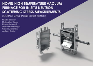
  • 1. NOVEL HIGH TEMPERATURE VACUUM FURNACE FOR IN SITU NEUTRON- SCATTERING STRESS MEASUREMENTS 15MPD101 Group Design Project Portfolio Charles Brooker Christopher Davies Katrina Duncumb Michael Greenhough Yannis Kouparitsas Anthony Smith
  • 2. CURRENT RIG This portfolio follows the design process of the 15MPD101 Group Design Project. Ac- companying this port- folio is a report with full justifications for all design, material and manufacturing decisions made throughout the course of the project. The project looked at de- signing a high tempera- ture vacuum furnace for use in situ with a 100kN stress testing rig on the ENGIN-X beamline at the ISIS Facility in the Ruther- ford Appleton Laboratory, Oxfordshire. From examin- ing the current furnace, and consulting the team who in- teract with it, requirements were generated for the new design. The main design re- quirements were: - To be able to test samples at 1600°C - To be able to test in a vacuum environment - Reduce the amount of time taken to set up the furnace for testing Images of the current high temperature furnace for the ENGIN-X beamline Temperature produced by four infrared heaters situated around the sample Reaches a maximum temperature of 1100°C Has some inert atmosphere capabilities Side view of the furnace
  • 3. 2-3 Instron 100kN Stress Testing Rig Front and side views of the current furnace positioned on the rig
  • 4. INITIAL CONCEPTS Tube furnace concepts struggled with the small volume of space available to fit all of the necessary components
  • 5. 4-5 Initial concepts were devised for the design of the rig were based on the notion of a small tube containing the vacuum atmos- phere. This premise involved looking at connections to the test rig sample holders, as shown on the right, cooling of the sample holders and at- tachment of necessary water and pumps, as shown on the left. Although a tube vacuum would have been a smaller area to pump down and heat up, there were too many components that needed to be within close proximity to the sample (such as the induction heater and thermocou- ples) to make this idea feasible. Designs based on a larger chamber were then investigated. Possible bellows attachment methods for tube furnace Sample holder to bellows concept for tube furnace
  • 6. INITIAL CONCEPTS In contrast to the tube vacuum, a chamber vacuum was proposed, with several ideas put forward. Gull-wing, egg, and top hat designs were suggested, encompassing the whole rig, but these were identified as having issues with portability and vacuum compatibility. From these designs, a ver- tical cylindrical option was considered most appro- priate to be taken forward, as the shape would have minimal stress concentra- tors, and with proper sealing, would be able to sit on/with- in the test rig. Significant work was put into determining a good shape for the vacuum chamber, pri- or to proceeding forward with chamber design, and this can be found in Section 5.5.7 of the ac- companying report. Egg concept with hinged top Gull wing concept - hinged door with the test rig situated inside Top hat concept similar to those used in other high temperature vacuum furnaces
  • 7. 6-7 One issue of the furnace cur- rently in place on the ENGIN-X beamline was the ability to change heaters quickly whilst the furnace was on the rig, as infrared heaters have short lives. The current furnace did not address this, requiring several components to be removed to replace a heat- ing unit. Options proposed to solve this issue includ- ed: an “X-Wing” concept, where the heaters would fold down to be removed from either side; a con- cept that was top and bottom hinged, where heaters would fold up to be removed; and a slider concept, which could be removed as a whole and heaters slotted in. The slider design showed most promise, and was developed further. Slider concept with clip in heating elements top and bottom hinged concept - would require significant space for folding away Star Wars “X-Wing” style concept would involve attaching around sample in an unspecified way
  • 9. 8-9 Further development was carried out on the initial concepts to produce a final design. The vac- uum chamber, being a pressure vessel, was discussed at length in terms of shape, size, neutron compatibility, windows, seal- ing, and door design. Several door types were looked into, though a fully separated door was preferred over a hinged door to make sealing easier. Methods of closing the door, and sealing it to withstand negative pressure were re- searched and options were designed for the chamber. Some methods of attach- ment included bolting, clamping and clipping, with quick release style clips being favoured. Rubber seals were able to be used between the chamber and door flanges to prevent leak- age with a clip system.
  • 10. CONCEPT DEVELOPMENT Even with a chamber vacuum, the temper- ature requirements of the sample holders were still significantly higher than those of the current rig. The development of the sample holders there- fore primarily looked at cooling methods, converg- ing towards a spiral water channel design. Research conducted on the material requirements also necessi- tated the addition of sam- ple holder extensions for the highest temperature ranges, which would allow the remov- al of more heat before reaching the cooled sample holders. Sample holder extension for very high temperatures to reduce heat transferred to sample holders and rig
  • 11. 10-11 The slider was chosen as a sim- ple concept for inserting/re- moving infrared heaters, but it also allowed induction heating to be used when the design was turned into a frame, as the centre could be used for any pipes or cables that were needed for heating or cool- ing. The simplicity of the design allowed it to be in- tegrated into the vacuum chamber easily with rails top and bottom, and re- moving a broken infrared heater would be as sim- ple as disconnecting the pipes/cables, sliding the module out, and unclip- ping it, with replacement simply being the re- verse. Slider concept pulled back to a skeletal frame for easier manufacturing, also allowing induction heating elements to be connected through the module Solid piece slider concept would be difficult to manu- facture and require signifi- cant machining of holes Connection to the vacuum chamber through a protruding rail on the slider module and a holding rail in the vacuum chamber A clip system would allow the infrared heaters to be quickly inserted or removed from the module
  • 12. FINAL CONCEPT The final design con- sisted of four main components: the vac- uum chamber; the chamber door; the sample holders; and the slider mechanism. The chamber and door, as shown on the right, will fit between the two Instron stress rig bars, and allow enough room in when closed for both methods of heating, sensors, and the sam- ple and sample holders. There were many changes made after the final con- cept drawing of the vacuum chamber, including the ad- dition of handles and hoists, these can be seen in the CAD images and drawings on pag- es 16 – 21. Thea sample holders, shown on the left, will screw into the Instron stress rig arms, and be attached to sets of bellows to allow for the movement of the arms during testing. The inter- nal cooling channels will be hel- ical, and at higher temperatures extensions will reduce the heat being transmitted to the sample holders. Sample holder extension for very high temperatures sample holder with bellows connections shown to vacuum chamber
  • 13. 12-13 Sample holder entry holes were positioned in the middle of the chamber, with test rig rails holes ouside of the chamber Flanges located on both door and chamber for vacuum sealing Quick release clip points positioned around the chamber and door Neutron entry and exit windows positioned for diffraction detection
  • 14. FINAL CONCEPT Around the edge of the vacuum chamber and door, several clips will secure the position and seal the chamber shut, as shown on the left. These clips are quick release and will improve the time it takes to set up on the Instron stress rig for testing. There will be two slider modules for the vacuum chamber, top and bottom, which will house the infra- red heaters and the induc- tion coil as two methods of heating the sample. Cooling and power will be supplied to the modules through the roof of the chamber, and uti- lising the space in the centre of the module to direct these tubes and cables to the correct heating method. The infrared heaters clip in and out of the slider module, to allow for quick changing if one is not function- ing correctly. Approximate placement of the quick attachment mechanisms on the door and chamber
  • 15. 14-15
  • 16. COMPUTER AIDED DESIGN From the concept devel- opment stage, Computer Aided Design (CAD) soft- ware was used to create a 3D representation of the chamber, sample hold- ers and sliders. The use of CAD aided the group in making design decisions throughout the project, as the software creates mod- els to scale, which can be used for prototyping; allows manipulation of viewpoint, to aid in visualisation of the product; and can create as- semblies to check for any in- terference between the compo- nents. CAD model iterations Full assembly model Open door assembly Slider module Chamber door Vacuum chamber
  • 17. 16-17