1. Specifications, Applications,
Service Instructions & Parts
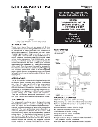
HCK5D
GAS-POWERED, 2-STEP
SUCTION STOP VALVE
1-1/2˝ THRU 4˝ PORT
(40 mm THRU 100 mm)
Bulletin C429a
MAY 2011
HCK5D
2-Step Gas-Powered Suction Stop Valve
Flanged
1-1/2˝ thru 4˝
SW, WN, ODS
for refrigerants
INTRODUCTION
These heavy-duty, flanged, gas-powered, 2-step
suction stop valves are designed to control the flow
of refrigerant in large industrial and commercial
refrigeration systems. They remain normally open
via a spring and require no pressure drop to operate.
A single pilot solenoid valve is required to control a
higher pressure refrigerant gas which closes these
valves during defrosting. The HCK5D valve has an
internal, controlled bleed-down (equalize) feature
which will not allow the main seat to open until the
pressure across the valve is at a lower, safer pressure
differential. This eliminates the need for a separate
bleed-down solenoid valve, greatly simplifying piping
and reducing installation costs. If a loss of power
occurs during defrost, evaporator pressure is utilized
to keep the main valve seat closed until bleed-down
is complete.
APPLICATIONS
The HCK5D valve is ideally suited for positive closure
of suction, liquid overfeed, and flooded evaporator
gas return lines during defrost in low temperature
applications. These valves can be installed in
horizontal or vertical lines and are best installed on
their sides for improved conveyance of liquid and oil.
Because they are gas-powered to close, the valves
operate reliably even under viscous oil conditions.
They are suitable for Ammonia, Halocarbons, CO2
and other Hansen approved refrigerants and gases.
ADVANTAGES
The unique self-equalizing piston design eliminates
the need and cost for a separate equalizing solenoid
valve and piping and associated wiring and controls.
A single high pressure source is the only pilot piping
required. The main piston/seat opens based on a
pressure difference between the evaporator and
suction pressure. Bleed rate is adjustable via screw-in
orifice discs. The ductile iron body is much stronger
and tougher than grey iron or “semi-steel” iron.
Protective pilot line disc strainers are included. Manual
opening stems are standard for positive opening
during servicing or trouble shooting of the systems.
key FEATURES
additional features
Internal, self-equalizing piston assembly
Requires only one pilot solenoid valve for operation
Remains closed until pressure is equalized, during
loss of power
Adjustable bleed rate via orificed plugs
No pressure drop required to open
Durable metal-to-metal seating
Tough ductile iron piston and body
Lower cost of installation
Flange-to-flange drop-in for standard Hansen HCK2
Gas powered suction stop valve
HCK5DW, Weld-In-Line available(contact Hansen)
M ANUAL
OPENING STEM
STAINLESS
STEEL
SPRING
STRONG, TOUGH
DUCTILE IRON
OR STEEL BODY
STRAINER
ACTUATED BY HIGH
PRESSURE GAS
UNIQUE
2-STEP
PISTON
ASSEMBLY
2. 2
C429a
MAY 2011
MATERIAL SPECIFICATIONS
Body: Ductile iron, ASTM A536 (Flanged Valve)
Cast Steel, ASTM A352, grade LCB
(HCK5DW Weld-In-Line Valve)
Top Cover: Steel, ASTM A36
Piston Seat: Ductile iron, ASTM A536
Spring: Stainless steel
Gaskets: Non-asbestos, graphite composite
Stem: Plated steel
Stem Seal: O-ring plus graphite composite packing
Seal Cap: Steel, zinc chromate plated
Companion Flanges: Forged steel ASTM A105
Safe Working Pressure: 400 psig (27 bar), 600 psig
(40 bar) for CO2
Operating Temperature: –60°F to +240°F (–50° to
115°C)
OPERATION
These valves are normally held fully open by means
of a spring. When a high pressure refrigerant gas is
introduced to the valve through the pilot line inlet,
the Upper Piston and Lower Piston are forced down,
compressing the Opening Spring and seating the Lower
Piston firmly on the valve body taper seat. While the
HCK5D is designed to withstand the shock of quick
closing, if the noise or system or piping shock is
excessive, a lower controlled refrigerant gas pressure
may be advisable. Use an outlet pressure regulator,
a hand expansion valve, or an orifice.
For valve equalization, the high pressure gas source
is interrupted and the upstream pressure raises the
Upper Piston while continuing to firmly force the Lower
Piston against the valve body taper seat. This allows
the refrigerant on the inlet side of the valve to escape
in a controlled manner, through four orificed plugs.
The valve will fully open when the downward force on
the Lower Piston caused by the difference in pressure
between the valve inlet and the outlet is reduced
below the upward force due to the compression of
the Opening Spring. This typically occurs in the
range of 8-12 psi differential. It is advisable to allow
ample time for the valve to equalize to a differential
pressure below this range so the valve can open. For
most applications 4 minutes should be adequate. If
necessary, orificed plugs can be enlarged or removed
to decrease bleed down time. Observation in the field
may yield a more accurate bleed down time as the
valve action is very repeatable.
Because of the constant bleed around the Upper Piston
when fully closed, these valves are recommended
where closure is for short periods, such as during
defrost, or where bleed to suction is not objectionable.
When a constant bleed to suction is not desired, use
a Hansen HS9B gas powered solenoid valve having a
piston seal ring and dual pilot solenoid valves.
INSTALLATION
Protect the interior of the valves from dirt and moisture
during storage and installation. These valves may be
installed upright or on their sides in either a vertical or
horizontal line. The arrow on the valve body should be
in the normal direction of refrigerant flow. The System
should be free of dirt, weld slag, and rust particles.
These valves require only a single pilot solenoid valve
to close. A 1/2˝ (13 mm) port Hansen HS8A solenoid
valve with strainer and ¾” minimum pipe line sizing is
recommended to control a high pressure gas source
to the HCK5D. (If using a refrigerant liquid for the high
pressure source, a Hansen HS9B with bypass gas-
powered solenoid valve is recommended, instead of
the HCK5D.) The field installed pilot solenoid valve
must be connected upstream of any hot gas defrost
solenoid valve and should be located as close as
possible to the main valve. This will help maintain
full high pressure gas to the top of the piston/seat
and minimize the amount of high pressure gas to
be relieved past the piston/seat upon termination of
the high pressure source. Where two HCK5D valves
are to be operated simultaneously, a 1/2˝ port pilot
solenoid valve and pilot line strainer assembly should
be installed in each pilot line.
For proper flange gasket sealing, care must be taken
when threading or welding to ensure flanges are
parallel to each other and perpendicular to the pipe.
Also, the gaskets should be lightly oiled and all bolts
must be tightened evenly.
suction vapor capacities - tons (kW)
(1 Ton=12,000 Btu/hr=3.517 kW)
APPLICATION
PORT SIZE (MM)
1-1/2˝ (40) 2˝ (50) 2-1/2˝ (65) 3˝ (80) 4˝ (100)
R717
+20ºF (-6.7ºC) 58 (204) 68 (239) 110 (387) 156 (549) 341 (1199)
0ºF (-17.8ºC) 47 (165) 55 (193) 90 (317) 127 (447) 278 (978)
-20ºF (-28.9ºC) 38 (134) 44 (155) 73 (257) 101 (355) 221 (777)
-40ºF (-40.0ºC) 29 (102) 34 (120) 55 (193) 78 (274) 171 (601)
R22
+20ºF (-6.7ºC) 24 (84) 28 (98) 46 (162) 65 (229) 143 (503)
0ºF (-17.8ºC) 21 (74) 24 (84) 39 (137) 55 (193) 121 (426)
-20ºF (-28.9ºC) 17 (60) 20 (70) 32 (113) 45 (158) 99 (348)
-40ºF (-40.0ºC) 14 (49) 16 (56) 26 (91) 36 (127) 80 (281)
Cv (Kv) 47 (40) 55 (47) 89 (76) 126 (108) 276 (236)
Above capacities are based on liquid temperature equal to evaporator temperature and 1 psi (0.07 bar) drop through the valve.
For 0.5 psi (0.035 bar) drop, multiply above values by 0.71. For liquid overfeed systems, nominal 2:1 to 5:1 ratio, add 20% to
the evaporator load and select a valve based on the increased load. For gravity flooded application, valve should be same port
size as properly sized liquid leg or gas line. Consult flooded evaporator manufacturer for proper line sizing.
3. 3
C429a
MAY 2011
valve shown in refrigeration (valve open)
valve shown in equalization (bleed down)
valve shown in defrost (valve closed)
"DEFROST"
UPPER PISTON
PILOT VALVE
PILOT LINE
HIGHER
PRESSURE
GAS
LOW ER PISTON
OPENING SPRING
LOW ER PISTON
BLEED HOLES
OPENING SPRING
UPPER PISTON
FOUR NPT ORIFICE PLUGS
CONTROL BLEED DOW N
"BLEED-DOW N"
HIGH P
"REFRIGERATION"
LOW P
UPPER PISTON LOW ER PISTON
OPENING SPRING
4. 4
C429a
MAY 2011
PORT SIZE
(MM)
DIMENSIONS (MM)
H1
* H4
L
L1
L2
L4
W
SW WN, ODS
1-1/2˝, 2˝
(40), (50)
7.12˝
(107)
9.55˝
(243)
12.39˝
(315)
13.39˝
(340)
9.88˝
(251)
0.86˝
(22)
10.89˝
(277)
4.50˝
(114)
2-1/2˝
(65)
8.06˝
(205)
10.23˝
(260)
13.01˝
(330)
14.03˝
(356)
9.88˝
(251)
1.15˝
(29)
11.01˝
(280)
5.62˝
(143)
3˝
(80)
8.38˝
(213)
10.57˝
(268)
15.38˝
(391)
16.40˝
(417)
12.25˝
(311)
1.15˝
(29)
13.38˝
(340)
6.50˝
(165)
4˝
(100)
9.88˝
(251)
11.45˝
(291)
17.01˝
(432)
20.51˝
(521)
14.12˝
(359)
1.50˝
(38)
15.01˝
(381)
8.06˝
(205)
*Allow additional 2.75˝ (70 mm) for seal cap removal. W= maximum width of valve.
INSTALLATION DIMENSIONS
1-1/2˝ thru 4˝
(40 mm thru 100 mm)
1
1
4
4
2
L
L
L
H
H
L
special application
Flooded Evaporators
Install the HCK5D in the gas leg of the evaporator.
Use a Hansen HCK2 in the liquid leg of the evaporator,
installed in the normal direction of refrigerant flow.
Size the hot gas line for ¾˝ minimum when feeding
two HS8A pilot solenoid valves.
5. 5
C429a
MAY 2011
troubleshooting
FAILURE TO CLOSE
• Pilot solenoid valve is not opening due to an
electrical problem.
• Disc strainer or high pressure pilot line may be
plugged.
• Pilot pressure source may not be high enough.
It should be at least 20 psi (1.4 bar) above the
pressure through the main valve.
• Manual opening stem is turned in.
• Dirt may have lodged between the upper piston
and the valve body piston bore.
FAILURE TO OPEN
• Pilot solenoid is jammed open with dirt.
• Pilot solenoid manual opening stem is turned in.
• Valve differential pressure is not being allowed
to fall below 8 psi during bleed down. Increase
bleed down time or remove one or more plugs.
• Pilot pressure and pressure through the main
valve are not equalizing.
• Check for reverse installation of the main valve.
• Dirt may be lodged between the upper piston and
valve body piston bore.
• The opening spring may be damaged or broken.
VALVE NOISY OR CHATTERS
• Pilot pressure gas and evaporator pressure
difference is too small. Adjust the defrost
relief pressure regulator setting. Check for
an undersized pilot solenoid valve (½”HS8A
recommended) and/or an undersized hot gas pilot
line.
VALVE SLAMS ON CLOSING
• Pilot pressure too high. Replace disc strainer in
pilot line with disc strainer/orifice. (Part number
78-0065) or add a hand expansion valve to meter
flow.
service and maintenance
MANUAL OPERATION
If it is necessary to manually hold open the HCK5D
valve:
• Cautiously remove the seal cap.
• Turn the manual opening stem inward (clockwise)
as far as possible.
• The entire piston should be mechanically held
open and the valve will not close until the manual
opening stem is turned out (counterclockwise).
• Do not operate the HCK5D automatically when
the manual opening stem is turned in or else the
stem may break after repeated cycles.
LOSS OF POWER
The HCK5D, when used with a normally closed solenoid
such as the recommended HS8A, will equalize before
opening in the event of loss of power to the pilot
solenoid coil.
DISASSEMBLY
If it is necessary to remove or disassemble the valve
for servicing, be sure the high pressure pilot line
and main valve are completely isolated from the
refrigeration system and all refrigerant is removed
(pumped out to zero pressure). Be sure to follow
refrigeration system safety procedures. Disconnect
the pilot line, and clean or replace the disc strainer/
orifice assembly as necessary.
To inspect the valve interior, after removing pressure,
slowly loosen the cover bolts equally and break the
gasket seal, being careful to avoid any refrigerant
which may still remain. Remove the cover bolts and
cover. Use the tapped hole in the top of upper piston
to remove it. Use the same procedure to remove the
lower piston. In most cases, the cover bolts can be
used. A 5/8˝-11 bolt is required to remove the 2˝ lower
piston. Clean and inspect the 4 orifice holes. Verify
that the path is clear in each. Clean and inspect the
following surfaces for wear and damage:
• Taper seat in valve body
• Contact surfaces of lower piston
• Contact surfaces of upper piston
Slight marks and burrs can often be removed with
emery paper by hand or power lapping. Damaged parts
should be replaced. After cleaning and inspection,
lightly lubricate the interior of the upper piston.
Carefully slide the lower piston inside the upper
piston. The upper piston should move smoothly on
the lower piston and should make good contact with
the ductile iron seal surface. Lightly lubricate the main
valve interior bore with refrigerant oil and install the
spring and piston assembly. Manually simulate valve
operation by pushing on top of the piston assembly.
Action should be smooth and the spring should readily
push the entire piston assembly back. Re-assemble
the cover, gasket and bolts, pilot line and disc strainer.
Carefully check the entire valve for leaks prior to
restoring the valve to service.
BONNET BOLT TORQUE
SPECIFICATIONS
PORT SIZE
(mm)
BOLT TORQUE
FT-LB
(Nm)
1-1/2˝ - 2˝
(40, 50)
40
(55)
2-1/2˝
(65)
100
(140)
3˝
(80)
100
(140)
4˝
(100)
150
(210)