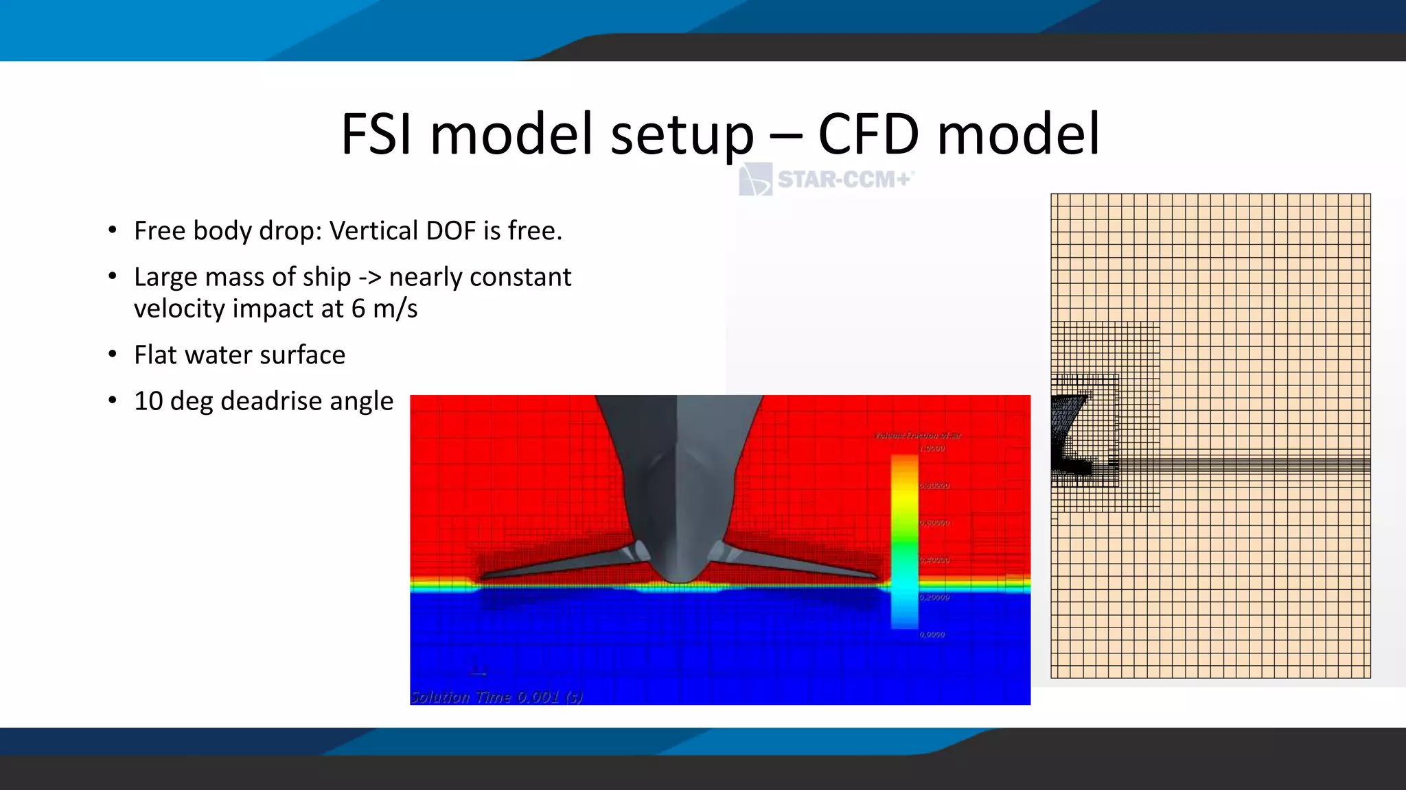
This document summarizes a fluid-structure interaction (FSI) analysis of a composite bow foil. The analysis compared a quasi-static structural analysis, dynamic structural analysis with rigid CFD, and a full FSI analysis with two-way fluid-structure coupling. The FSI analysis found a 40-50% reduction in bending moment and vertical force compared to the quasi-static analysis. Compressible air effects provided a minor 10% difference from an incompressible analysis. The hydroelasticity parameter indicated structural dynamics were important given the short load duration. Overall, the FSI and dynamic analyses provided a lighter and more optimized structural design compared to a traditional quasi-static approach.

![Time step convergence
0
0.2
0.4
0.6
0.8
1
1.2
0.00E+00 2.00E-05 4.00E-05 6.00E-05 8.00E-05 1.00E-04 1.20E-04
Verticalforce/CFL
Timestep [s]
Vertical force CFL
0.00
0.10
0.20
0.30
0.40
0.50
0.60
0.70
0.80
0.90
1.00
1.10
1.20
0.035 0.037 0.039 0.041 0.043 0.045 0.047
Verticalforce[MN]
Time [s]
dt=1e-4 dt=2.5e-5 dt=1e-5
• CFL < 1 gives sufficient accuracy on forces (average of pressure)](https://image.slidesharecdn.com/nafemsnordic2018-180427090906/75/cDynamics-AS-NAFEMS-Nordic-2018-Presentation-7-2048.jpg)
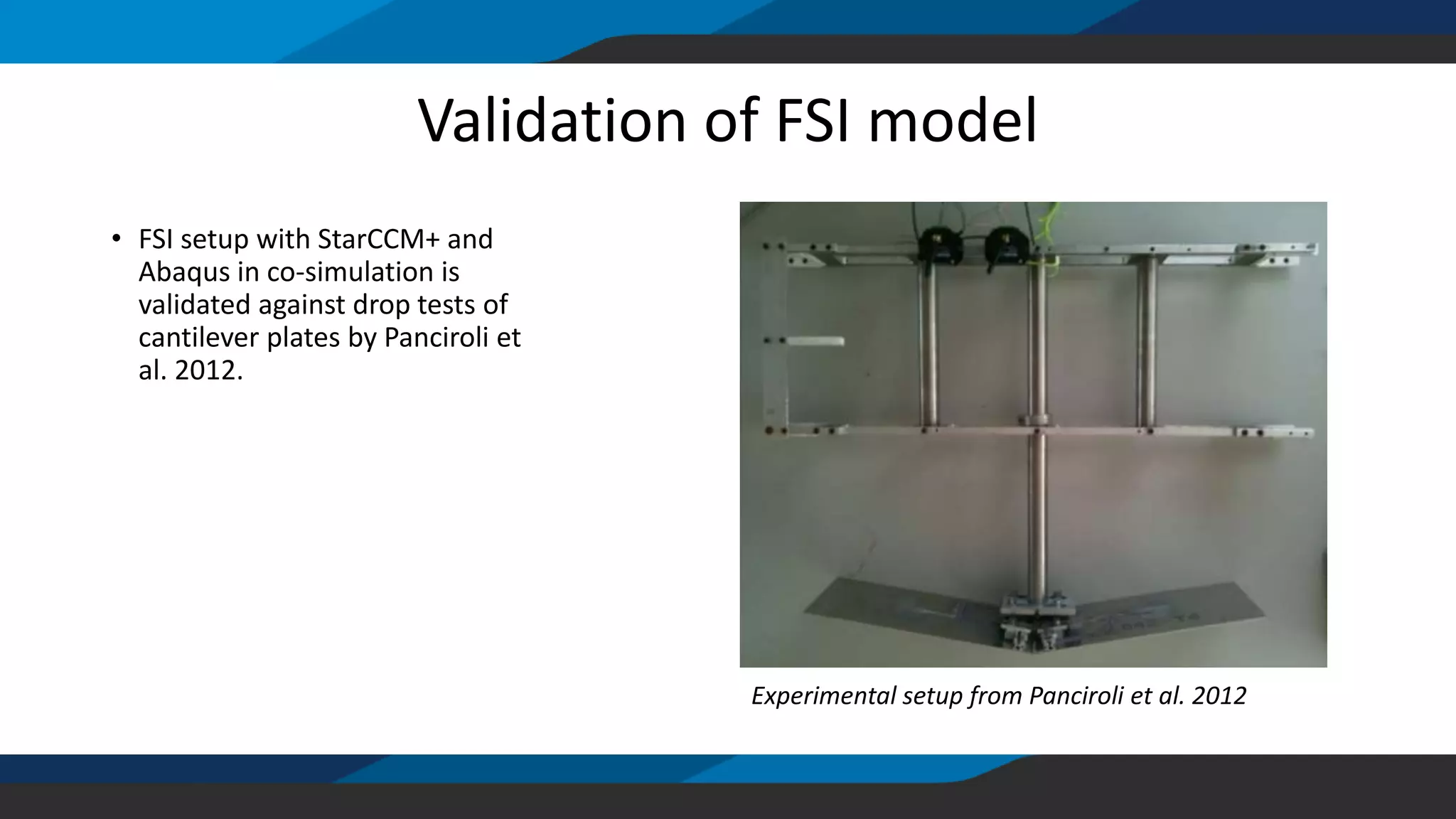

![Validation of FSI model
Experimental data from Panciroli et al. 2012
-0.002
-0.0015
-0.001
-0.0005
0
0.0005
0.001
0.0015
0.002
0.0025
0 0.01 0.02 0.03 0.04 0.05 0.06 0.07
Strain[%]
Time[s]
FSI (CFD)
Experiment (Panciroli)
• FSI setup with StarCCM+ and
Abaqus in co-simulation is
validated against drop tests of
cantilever plates by Panciroli et
al. 2012.](https://image.slidesharecdn.com/nafemsnordic2018-180427090906/75/cDynamics-AS-NAFEMS-Nordic-2018-Presentation-12-2048.jpg)
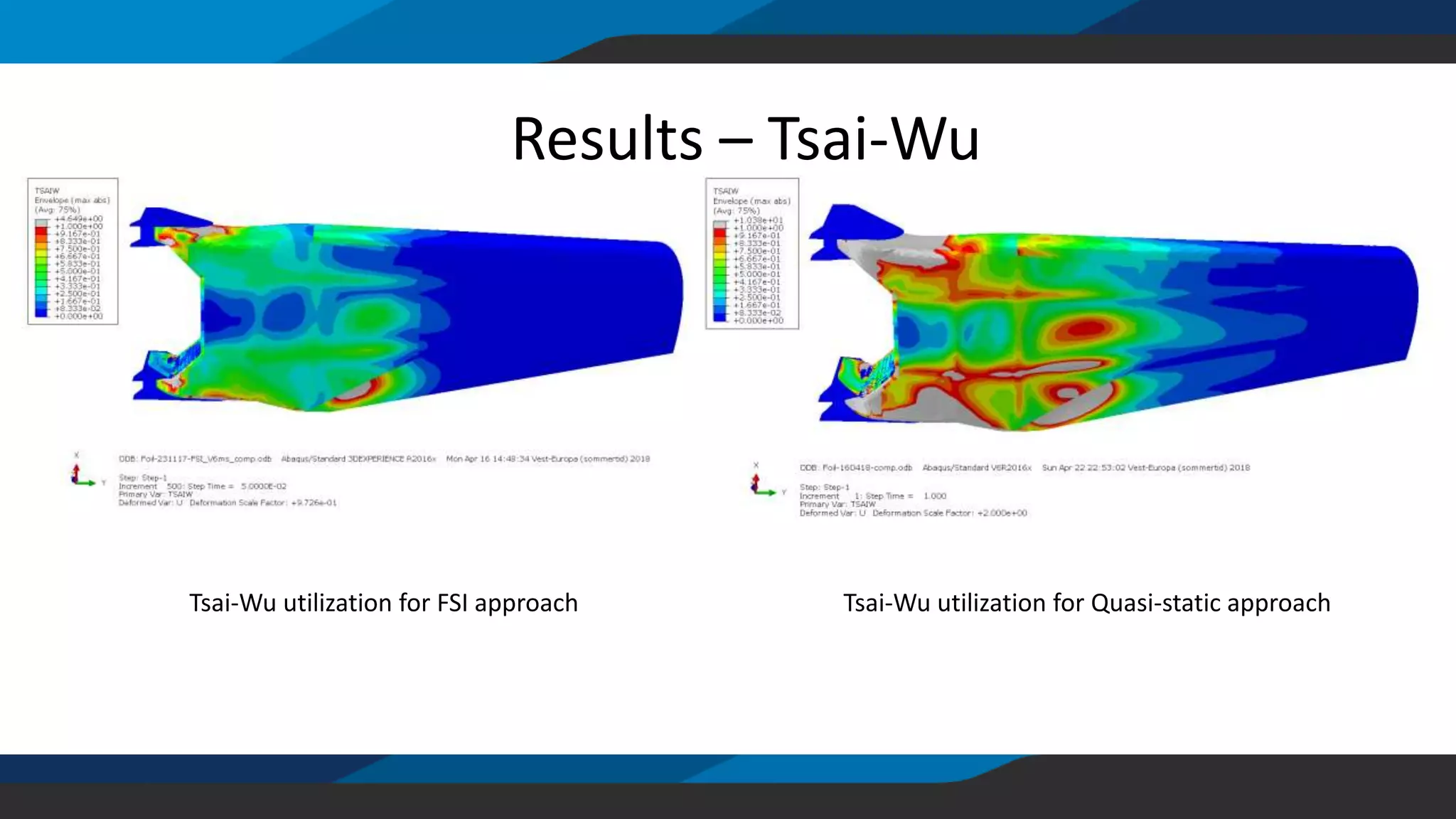
![Results - compressible air effects
• FSI versus quasi-static yields
reduction of bending moment of
50%
• Dynamic vs quasi-static yields
reduction of bending moment of
50%
-0.9
-0.7
-0.5
-0.3
-0.1
0.1
0.3
0.5
0.7
0.9
1.1
1.3
1.5
1.7
1.9
2.1
0.02 0.025 0.03 0.035 0.04 0.045 0.05 0.055 0.06 0.065
Verticalforce[MN]
Time [s]
Quasi-static Quasi-static (incompressible air)
• Compressible air effects are
relevant
• Part of Hull adjacent to foil
needs to be included in CFD
model](https://image.slidesharecdn.com/nafemsnordic2018-180427090906/75/cDynamics-AS-NAFEMS-Nordic-2018-Presentation-13-2048.jpg)
![• FSI approach renders vertical
force about 40% of quasi-static
• Dynamic approach gives spurious
oscillations because of no
damping
-0.9
-0.7
-0.5
-0.3
-0.1
0.1
0.3
0.5
0.7
0.9
1.1
1.3
1.5
1.7
1.9
2.1
0.02 0.025 0.03 0.035 0.04 0.045 0.05 0.055 0.06 0.065Verticalforce[MN]
Time [s]
Quasi-static FSI Dynamic
Results – vertical force](https://image.slidesharecdn.com/nafemsnordic2018-180427090906/75/cDynamics-AS-NAFEMS-Nordic-2018-Presentation-14-2048.jpg)
![• FSI bending moment about 40% of
quasi-static
• Dynamic bending moment about
60% of quasi-static
• Incompressible air effects yields
only 10% difference to FSI bending
moment
-0.4
-0.2
0.0
0.2
0.4
0.6
0.8
1.0
1.2
1.4
1.6
1.8
2.0
2.2
2.4
0.02 0.025 0.03 0.035 0.04 0.045 0.05 0.055 0.06 0.065
Bendingmoment[MNm]
Time [s]
Quasi-static FSI (two-way coupling) Dynamic (One-way coupling) FSI (incompressible)
Results – bending moment](https://image.slidesharecdn.com/nafemsnordic2018-180427090906/75/cDynamics-AS-NAFEMS-Nordic-2018-Presentation-15-2048.jpg)


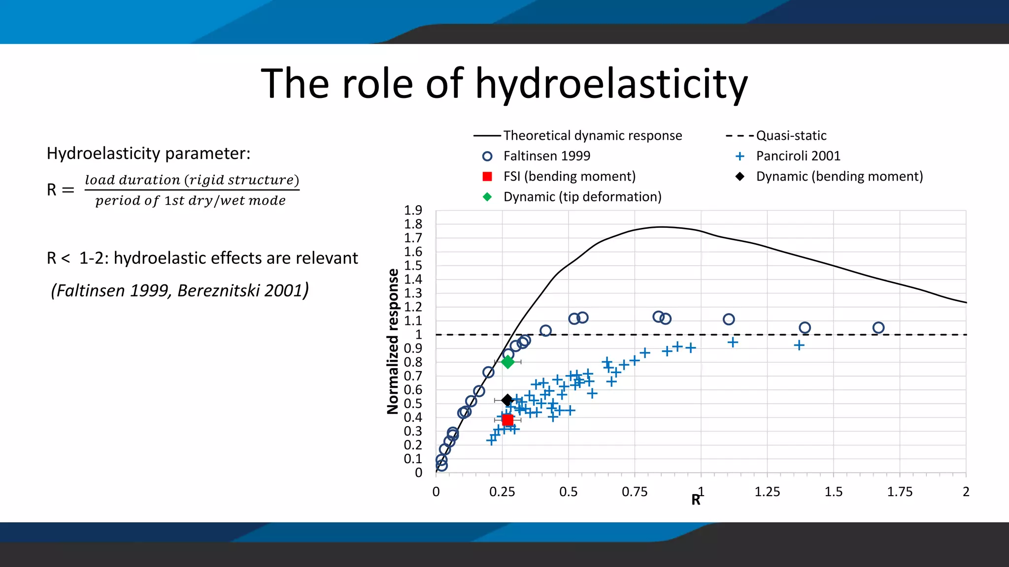
![The role of hydroelasticity
-0.9
-0.7
-0.5
-0.3
-0.1
0.1
0.3
0.5
0.7
0.9
1.1
1.3
1.5
1.7
1.9
2.1
0.02 0.022 0.024 0.026 0.028 0.03 0.032 0.034 0.036 0.038 0.04 0.042 0.044 0.046 0.048 0.05 0.052 0.054 0.056 0.058 0.06 0.062 0.064
Verticalforce[MN]
Time [s]
Quasi-static
Duration=5-10 ms
R=0.2-0.3
Hydroelasticity parameter:
R =
𝑙𝑜𝑎𝑑 𝑑𝑢𝑟𝑎𝑡𝑖𝑜𝑛 (𝑟𝑖𝑔𝑖𝑑 𝑠𝑡𝑟𝑢𝑐𝑡𝑢𝑟𝑒)
𝑝𝑒𝑟𝑖𝑜𝑑 𝑜𝑓 1𝑠𝑡 𝑑𝑟𝑦/𝑤𝑒𝑡 𝑚𝑜𝑑𝑒
R < 1-2: hydroelastic effects are relevant
(Faltinsen 1999, Bereznitski 2001)](https://image.slidesharecdn.com/nafemsnordic2018-180427090906/75/cDynamics-AS-NAFEMS-Nordic-2018-Presentation-20-2048.jpg)


![Modeling and Structural Analysis of a Wing [FSI ANSYS&MATLAB]](https://cdn.slidesharecdn.com/ss_thumbnails/finalreport-191222214155-thumbnail.jpg?width=640&height=640&fit=bounds)


