SlideShare a Scribd company logo
1 of 9
Download to read offline
Europaisches Patentamt
European Patent Office
Dffice europeen des brevets
5) Publication number. 0 3 0 8 9 9 0
EUROPEAN PATENT A P P L I C A T I O N
© Application number: 88116206.9
© Date of filing: 31.08.83
nt. CI.4 B60S 1/08
§) Priority: 02.09.82 JP 151729/82 © Applicant: NISSAN MOTOR CO., LTD.
02.09.82 JP 151730/82 No.2, Takara-cho, Kanagawa-ku
20.09.82 JP 162176/82 Yokohama City(JP)
S) Date of publication of application: © Inventor: Shiraishi, Yasuhiro
29.03.89 Bulletin 89/13 B-312, Nissansagamiryo 4688-1, Sobudai
3-chome
S) Publication number of the earlier application in Zami-shi Kanagawa-ken(JP)
accordance with Art.76 EPC: 0 102 622
© Representative: Patentanwalte Griinecker,
£) Designated Contracting States: Kinkeldey, Stockmair & Partner
DE FR GB IT Maximilianstrasse 58
D-8000 Munchen 22(DE)
© Wiper speed control system for an automotive windshield wiper.
© A wiper speed control system for an automotive
wiper controls the operational speed of a wiper in
accordance with rain conditions. The control system
includes a rain sensor (30) detecting rain conditions
to produce . an analog signal having an amplitude
depending upon the detected rain conditions. The
analog sensor signal is converted into a digital pulse
signal by a converter (12) for application to a digital
circuit system. A control signal is produced by
digitally processing the pulse signal. The control
signal is applied to a wiper driver circuit to adjust the
operational speed or timing in accordance with the
control signal.
F I G . 3
Oi
O)
00
o
CO
o
Q_
UJ
30
R
A
I
N
SENSOR
) JUL
1 r
rULofc
SIGNAL
G
E
N
E
R
A
T
O
R
34) JUL!
52
- L
M
E
C
H
A
N
I
S
M
JL
OSCILLATOR J
C
O
N
T
R
O
L
| CIRCUIT
U
KIvert t
V
H
_
M
V
^
n
j
univcn winwui i
IO
—I
xerox uopy centre
:P 0 308 990 A1 I
/VIPER SPEED CONTROL SYSTEM FOR AN AUTOMOTIVE WINDSHIELD WIPER
3ACKGROUND OF THE INVENTION
The present invention relates generally to a
wiper control system for an automotive windshield
viper, which automatically controls the operating
speed of the wiper in dependence upon rain con-
iitions. More particularly, the invention relates to a
wiper control system which can avoid the influence
D
f external conditions on detection of rain con-
jitions.
Published Japanese Utility Model Application
No. 57-130747. published on August 14, 1982 dis-
poses an automatic control system for an auto-
motive wiper. The automatic control system in-
cudes a vibration pick-up which detects vibrations
D
f the front window pane created by the impact of
-ain drops. The output signal of the vibration pick-
jp is amplified, filtered and then compared with a
threshold to produce a driver signal when the out-
put signal level exceeds the threshold level.
In this wiper control system, since the com-
parator compares an analog vibration pick-up out-
put with an analog threshold, and since the am-
plifier, filter and comparator all perform analog pro-
cessing, they are apt to be influenced by external
conditions such as errors in the operational char-
acteristics of the respective circuit elements, or
temperature conditions. These influences may
cause the wiper operation to be deviated from that
required.
SUMMARY OF THE INVENTION
Therefore, it is an object of the present inven-
tion to provide a wiper speed control system which
satisfactorily and successfully avoids the influence
of external conditions on detection of rain con-
ditions.
Another and more specific object of the
present invention is to provide a wiper speed con-
trol system, which performs digital processing to
detect rain conditions and to control operation of
the automotive wiper mechanism.
To accomplish the foregoing and other objects,
a wiper speed control system according to the
present invention includes a control circuit which
can convert an analog rain sensor signal into a
pulse signal suitable for digital processing. In prac-
tice, the pulses of the pulse signal are counted and
compared with a predetermined threshold value to
produce a driver signal when the counter value
becomes equal to the predetermined threshold val-
ue.
By controlling the wiper operation according to
the digitally processed rain condition data, the in-
fluence on detection of the rain conditions due to
external conditions can be satisfactorily and suc-
5 cessfully avoided.
According to one aspect of the invention, a
wiper control system for an automotive wiper com-
prises a ranin sensor for producing a sensor signal
having a value indicative of rain conditions, means
w for producing a digital rain-condition data signal
according to the sensor signal value, means for
producing a wiper control signal based on said
• rain-condition data signal, and a wiper driver motor
responsive to the wiper control signal to drive a
7
5 wiper at a rate variable in accordance with the
wiper control signal.
In another aspect, a wiper speed control sys-
tem for an automotive wiper comprises a rain sen-
sor including a vibrator with a sensor surface ex-
20 posed to rain and vibrating in accordance with rain
conditions, the rain sensor producing a sensor sig-
nal having an amplitude corresponding to the mag-
nitude of vibration of the vibrator, a converter
means for converting the sensor signal into a digi-
25 tal signal representative of the detected rain con-
ditions, means for processing the digital signal to
produce a driver signal, and a wiper driver motor
responsive to the driver signal for driving a wind-
shield wiper at a rate variable in accordance with
30 the driver signal.
BRIEF DESCRIPTION OF THE DRAWINGS
35 The present invention will be understood more
fully from the detailed description give below and
from the accompanying drawings of the preferred
embodiment of the invention, which, however,
should not be taken to limit the invention to the
40 specific embodiment but for explanation and under-
standing only.
In the drawings:
Fig. 1 is a schematic block diagram of the
preferred embodiment of a wiper speed control
45 system according to the present invention;
Fig. 2 is a sectional view of a rain sensor
employed in the wiper speed control system of Fig.
1;
Fig. 3 is schematic block diagram of a modi-
50 fication of the wiper speed control system of Fig. 1;
Fig. 4 is a diagram illustrating location of a
rain sensor on a vehicle with regard to dynamic air
pressure;
!P 0 308 990 A1
Fig. 5 is a diagram of application of the rain
lensor to the wiper speed control system of Fig. 3;
md
Fig. 6 illustrates the vibration frequency
ipectrum acting on the rain sensor.
DESCRIPTION OF THE PREFERRED EMBODI-
MENT
Referring now to the drawings, particularly to
=ig. 1, a wiper speed control system of the pre-
:erred embodiment of the present invention gen-
3rally comprises a rain sensor 10 which detect rain
;onditions and produces a sensor signal having a
/alue indicative of the detected rain conditions. The
-ain sensor 10 is connected to a pulse signal
generator 12 which is adapted to shape the sensor
signal and to output a signal in the form of a train
3f pulses. The pulse train produced by the pulse
signal generator 12 has a frequency corresponding
to the sensor signal value and so indicating the
detected rain conditions. The pulse train is fed to a
counter 14. The counter 14 counts the pulses of
the pulse train and produces a counter signal
whenever the counter value reaches a predeter-
mined value. The counter signal is fed to a driver
circuit 16 including a driver motor 18 to drive a
wiper mechanism 20.
As shown in Fig. 2, the rain sensor 10 com-
prises a vibration sensor having a sensor surface
102 inclined essentially parallel to the windshield
23 of a vehicle. The sensor surface 102 is formed
on a vibrator panel 104 secured in a sensor hous-
ing 106 in turn rigidly secured to a cowl top panel
22 near the windshield 23. A piezoelectric element
108 is secured to the inner surface of the vibrator
panel 104 for vibration therewith.
In this design, the rain sensor 10 detects vibra-
tions produced by impact of rain drops on the
sensor surface. That is, when rain falls, rain drops
impinge on the sensor surface. Shock applied to
the sensor surface and the vibrator panel 104 var-
ies depending on the size of the colliding rain drop,
its speed at impact and frequency of occurence of
its collision. Therefore, the magnitude of vibration
caused by impact of rain drops varies depending
upon the size of the colliding rain drop, the colli-
sion speed and frequency of occurence of its colli-
sion. The piezoelectric element 108 vibrates with
the vibrator panel and produces a sensor signal
having a value corresponding to the magnitude of
vibration.
In summary, the sensor signal produced by the
rain sensor in the manner set forth above is an
analog signal, the output voltage of which varies in
dependence upon the vibration amplitude of the
vibrator panel and, in turn, in dependence upon xne
rain conditions. The pulse signal generator 12 con-
verts the analog signal into a pulse train suitable for
digital processing for the purpose of wiper speed
5 control. The counter 14 is a digital counter for
counting the pulses from the pulse signal generator
12 and internally compares the counter value with
a predetermined threshold value to produce a
counter signal when the counter value becomes
w equal to the threshold value.
When the wipers have been manually selected
to operate intermittently, the counter signal can
serve as a driver signal activating the driver circuit
to operate the wiper mechanism 20. In this case,
is the timing of occurrences of the counter signal
corresponds to the interval between successive
wiper operations, the frequency of which varies in
dependence upon rain conditions. However, ac-
cording to the shown embodiment it is also possi-
20 ble to control the wiper operational speed depend-
ing upon the detected rain conditions, even in low-
or high-speed continuous operation modes. In this
case, wiper speed control may be performed by
adjusting the voltage to be applied to the driver
25 motor 18 in accordance with the frequency of oc-
currence of the counter signal.
Fig. 3 shows a modification of the foregoing
preferred embodiment of wiper speed control sys-
tem according to the present invention. In this
30 modification, a rain sensor 30 is associated with the
pulse signal generator 12. As in the foregoing pre-
ferred embodiment, the rain sensor 30 produces an
analog sensor signal having a value indicative of
the rain conditions. The pulse signal generator 12
35 converts the analog sensor signal into a pulse train
having a frequency corresponding to the sensor
signal value. The pulse signal generator 12 is con-
nected to a counter 32. The counter 32 is also
connected to an oscillator 34 which is adapted to
40 output a pulse train with a constant frequency. The
counter 32 counts the pulses from both the pulse
signal generator 12 and the oscillator 34 and pro-
duces a counter signal when the counter value,
which represents the total number of pulses from
45 the pulse signal generator and the oscillator 34,
become equal to the predetermined threshold.
As shown in Figs. 4 and 5, the rain sensor 30
is mounted on the cowl top panel 22 of the vehicle
body at a point subject to positive pressure from
50 the air stream, as indicated by hatched area in Fig.
4. If the rain sensor 30 is mounted on the vehicle
body at a point subject to negative dynamic air
pressure, the air pressure may adversely influence
detection of rain conditions, since the angle of
55 incidence of the rain will be affected by the influ-
ence of the air pressure.
The sensor surface 302 of the rain sensor 30 is
inclined at a given angle with respect to the hori-
3
3 EP 0 308 990 A1
:ontal plane such that the rear edge is higher than
he front edge. The angle of inclination of the
sensor surface with respect to horizontal plane is
jmpirically selected to fall within the range of from
5° to 25°. Normally, rain drop speed is approxi-
mately 1 m sec, to 15 m/sec. In this normal rain
;ondition, the selected inclination angle of the sen-
sor surface, i.e. 5° to 25° is satisfactory for detect-
ng rain condition under usual vehicle speed.
Preferably, the rain sensor would be provided
with a sensor surface which can be variably in-
;lined in dependence upon the rain drop speed.
Dynamic air pressure reflecting vehicle speed may
oe used as a detecting parameter to control the
nclination angle of the sensor surface.
As in the foregoing embodiment, the rain sen-
sor 30 includes a vibrator panel 304 with a sensor
surface 302 exposed by a sensor housing 306. The
yibrator panel 304 engages the sensor housing 306
only at its circumferential edge so that it can
s/ibrate in response to impact of rain drops on the
sensor surface. A piezoelectric element 308 is se-
cured to the vibrator panel 304 via an electrode
310 formed therebetween. Another electrode 312 is
formed on the opposite surface of the piezoelectric
element 308. The electrodes 310 and 312 are
electrically connected to an amplifier 316. The am-
plifier 316 is connected to the wiper speed control
circuit, including the pulse signal generator 12, the
counter 32 and the oscillator 34, to supply the
sensor signal thereto.
The natural or natural resonate frequency of
the vibrator panel 304 is chosen to fall in the range
of 10 KHz to 25 KHZ. This specific natural fre-
quency of the vibrator panel is experimentarily se-
lected to avoid the influence of vibrations created
by the vehicle horn or other equipment or engine
vibrations. Fig. 6 shows the vibration frequency
spectrum created by vehicle horn and received by
the rain sensor. As will be appreciated from Fig. 6,
the maximum frequency of vibration created by the
vehicle horn is approximately 9 KHz. Therefore, by
selecting the natural frequency of the vibrator panel
304 in the given range, i.e., 10 KHz to 25 KHz, the
influence of the vehicle horn upon detection of the
rain conditions can be satisfactorily avoided.
The maximum natural frequency of the vibrator
panel 304 is selected in view of the amplitude of
the sensor signal. To achieve a natural resonant
frequency of the vibrator panel 304 beyond 25
KHz, the vibrator panel has to be adequately thick
in relation to the area of the sensor surface. In this
case, the amplitude of vibration produced by im-
pact of rain drops onto the sensor surface will be
too low to be used in the wiper control system.
That is, by setting the natural frequency of the
vibrator panel so high, the sensivity to rain will be
lowered, thereby degrading the response charac-
teristics of the wiper control system.
In this modification, since the counter signal is
produced when the total number of pulses from
both the pulse signal generator and the oscillator
5 reaches the predetermined threshold, the wiper
mechanism can be driven at the longest interval in
intermittent operational mode or at the lowest
speed in continuous operational mode, as defined
by pulse period of the pulse train from the oscilla-
o tor. As a result, the wiper mechanism will continue
to operate even when the vehicle passes through a
tunnel in which rain drop cannot be detected. This
will be advantageous for providing clear vision for
the driver.
7
5 It should be noted that the sensor surface
subjected to rain should be larger than 100 mm2 in
area in accordance with experimental results. In
experimental tests, it was found that a rain drop
impinging on a plane surface usually expands to an
20 area of approximately 100 mm2. It is necessary to
provide a sensor surface sufficiently large to re-
ceive the full volume of rain water upon impact in
order to detect the rain conditions. Otherwise, a
plurality of rain sensors, each of which has a sen-
25 sor surface area of less than 100 mm2, can be
used so that the total contiguous area of the sensor
surface exceeds 100 mm2.
As set forth above, according to the present
invention, an analog sensor signal is converted into
30 a pulse train so that the influence of errors in the
circuit element characteristics, temperature condi-
tions and so forth can be avoided.
35 Claims
1. An intermittent timing control system for a
wiper system of a vehicle, comprising :
a rain sensor (30) for monitoring rain condition to
40 produce a rain condition indicative sensor signal, a
control signal generator means (12, 32, 34) for
generating a wiper control signal on the basis of
said sensor signal and a wiper driver motor (18)
responsive to the control signal for driving a wind-
45 shield wiper (20) at variable intervals in an intermit-
tent mode of operation.
CHARACTERIZED IN THAT said rain sensor (30)
having a vibrator (304) adapted to oscillate at an
amplitude and frequency depending upon the rate
so of rain, said vibrator (304) having one surface (302)
exposed outwardly of said vehicle so that raindrops
directly collide with said one surface (302) for
causing oscillation of said vibrator (304), said one
surface (302) of said sensor (30) being mounted on
55 a point on a body of said vehicle subject to positive
pressure from an air stream travelling over said
vehicle and said vibrator (304) producing said sen-
sor signal having an amplitude and frequency cor-
4
7 EP 0 308 990 A I a
ssponding to the magnitude of vibration and fre-
uency of said one surface (302) ; and
aid means (12, 32, 34) is responsive to the mag-
itude and frequency of said sensor signal for
eriving an intermittent timing signal for wiper inter- 5
littent operation based on the sensor signal value.
2. The control system as set forth in claim 1
/herein said one surface (302) of said rain sensor
30) has an area greater than 100 mm2.
3. The control system as set forth in claim 1 or w
: wherein said one surface (302) of said rain sen-
or (30) is inclined at an angle relative to the
lorizontal.
4. The control system as set forth in claim 3
therein said angle is in the range of 5 degrees to 15
!5 degrees.
5. The control system as set forth in claim 4
/herein said angle is variable in dependence on
ain drop speed.
6. The control system as set forth in any of 20
:laims 1 to 5, wherein said one surface (302) is
nounted on a cowl top panel (22) of said vehicle.
to
J
0
EP 0 308 990 A1
F I G . 1
12
w w |
r a i n EHk?.1:
S E N S O R S I G N A L
b h N b U K
G E N E R A T O R
WIPER S P E E D
CONTROL C I R C U I T
2 0
z
W I P E R
M E C H A N I S M
,18
1 1
DRIVER M O T O R
DRIVER C I R C U I T
7
EP 0 308 990 A1
F I G . 3
I2>
J U L
3 2
J l
P U L S E
SIGNAL C O U N T E R
G E N E R A T O R —
3 4 ) J U L !
1
O S C I L L A T O R
W I P E R
S P E E D
C O N T R O L
C I R C U I T
2 0
I
W I P E R
M E C H A N I S M
8
i /
DRIVER M O T O R
DRIVER C I R C U I T
F I G . 4
EP 0 308 990 A1
F I G . 6
European Patent
Office
EUROPEAN SEARCH R E P O R T
Application Number
EP 88 11 6206
DOCUMENTS CONSIDERED TO BE RELEVANT
Category
Citation of document with indication, where appropriate,
of relevant passages
Relevant
to claim
CLASSIFICATION OF THL
APPLICATION (Int. CI.4)
Y
A
X
FUNKSCHAU
/ol. 50, no. 19, September 1978, DE,
pages 103-104; K.-H. SCHMIDT:
"Automati sche Schei benwi scher steuerung"
* column 4, line 59 - column 6, l i n e
33; figure 3 *
DE-U-7 005 022 (STEGER)
* page 1, lines 19-23; claim 2 *
PATENT ABSTRACTS OF JAPAN
/ol. 4, no. 105 (M-23) (587) 26th J u l y
1980; & JP - A - 55 063 941 (JEKO)
14-05-1980
DE-A-2 523 111 (0HE)
* page 3, line 25 - page 4, line 23 *
The present search report has been drawn up for all claims
1,3,6
B 60 S 1/08
1 , 3 , 6
4
1
1-3
TECHNICAL HELUS
SEARCHED (Int. C1.4)
B 60 S 1/00
Placeofsearch
BERLIN
Dateofcompletionofthesearch
12-12-1988
&
x
a
m
i
n
e
r
STANDRING M A
CATEGORY OFCITED DOCUMENTS
X: particularly relevant if taken alone
Y: particularly relevant if combined with another
document ofthe same category
A: technological background
O: non-written disclosure
P : intermediate document
T: theory or principle underlying the invention
E: earlier patent document, but published on, or
after the filing date
D: document cited in the application
L: document cited for other reasons
&: member ofthe same patent family, corresponding
document

More Related Content

Recently uploaded

Mondelez State of Snacking and Future Trends 2023
Mondelez State of Snacking and Future Trends 2023Mondelez State of Snacking and Future Trends 2023
Mondelez State of Snacking and Future Trends 2023Neil Kimberley
 
Call Girls Pune Just Call 9907093804 Top Class Call Girl Service Available
Call Girls Pune Just Call 9907093804 Top Class Call Girl Service AvailableCall Girls Pune Just Call 9907093804 Top Class Call Girl Service Available
Call Girls Pune Just Call 9907093804 Top Class Call Girl Service AvailableDipal Arora
 
Call Girls Kengeri Satellite Town Just Call 👗 7737669865 👗 Top Class Call Gir...
Call Girls Kengeri Satellite Town Just Call 👗 7737669865 👗 Top Class Call Gir...Call Girls Kengeri Satellite Town Just Call 👗 7737669865 👗 Top Class Call Gir...
Call Girls Kengeri Satellite Town Just Call 👗 7737669865 👗 Top Class Call Gir...amitlee9823
 
Call Girls Navi Mumbai Just Call 9907093804 Top Class Call Girl Service Avail...
Call Girls Navi Mumbai Just Call 9907093804 Top Class Call Girl Service Avail...Call Girls Navi Mumbai Just Call 9907093804 Top Class Call Girl Service Avail...
Call Girls Navi Mumbai Just Call 9907093804 Top Class Call Girl Service Avail...Dipal Arora
 
Pharma Works Profile of Karan Communications
Pharma Works Profile of Karan CommunicationsPharma Works Profile of Karan Communications
Pharma Works Profile of Karan Communicationskarancommunications
 
Ensure the security of your HCL environment by applying the Zero Trust princi...
Ensure the security of your HCL environment by applying the Zero Trust princi...Ensure the security of your HCL environment by applying the Zero Trust princi...
Ensure the security of your HCL environment by applying the Zero Trust princi...Roland Driesen
 
Cracking the Cultural Competence Code.pptx
Cracking the Cultural Competence Code.pptxCracking the Cultural Competence Code.pptx
Cracking the Cultural Competence Code.pptxWorkforce Group
 
Enhancing and Restoring Safety & Quality Cultures - Dave Litwiller - May 2024...
Enhancing and Restoring Safety & Quality Cultures - Dave Litwiller - May 2024...Enhancing and Restoring Safety & Quality Cultures - Dave Litwiller - May 2024...
Enhancing and Restoring Safety & Quality Cultures - Dave Litwiller - May 2024...Dave Litwiller
 
👉Chandigarh Call Girls 👉9878799926👉Just Call👉Chandigarh Call Girl In Chandiga...
👉Chandigarh Call Girls 👉9878799926👉Just Call👉Chandigarh Call Girl In Chandiga...👉Chandigarh Call Girls 👉9878799926👉Just Call👉Chandigarh Call Girl In Chandiga...
👉Chandigarh Call Girls 👉9878799926👉Just Call👉Chandigarh Call Girl In Chandiga...rajveerescorts2022
 
Value Proposition canvas- Customer needs and pains
Value Proposition canvas- Customer needs and painsValue Proposition canvas- Customer needs and pains
Value Proposition canvas- Customer needs and painsP&CO
 
Phases of negotiation .pptx
 Phases of negotiation .pptx Phases of negotiation .pptx
Phases of negotiation .pptxnandhinijagan9867
 
Call Girls Electronic City Just Call 👗 7737669865 👗 Top Class Call Girl Servi...
Call Girls Electronic City Just Call 👗 7737669865 👗 Top Class Call Girl Servi...Call Girls Electronic City Just Call 👗 7737669865 👗 Top Class Call Girl Servi...
Call Girls Electronic City Just Call 👗 7737669865 👗 Top Class Call Girl Servi...amitlee9823
 
Dr. Admir Softic_ presentation_Green Club_ENG.pdf
Dr. Admir Softic_ presentation_Green Club_ENG.pdfDr. Admir Softic_ presentation_Green Club_ENG.pdf
Dr. Admir Softic_ presentation_Green Club_ENG.pdfAdmir Softic
 
B.COM Unit – 4 ( CORPORATE SOCIAL RESPONSIBILITY ( CSR ).pptx
B.COM Unit – 4 ( CORPORATE SOCIAL RESPONSIBILITY ( CSR ).pptxB.COM Unit – 4 ( CORPORATE SOCIAL RESPONSIBILITY ( CSR ).pptx
B.COM Unit – 4 ( CORPORATE SOCIAL RESPONSIBILITY ( CSR ).pptxpriyanshujha201
 
Business Model Canvas (BMC)- A new venture concept
Business Model Canvas (BMC)-  A new venture conceptBusiness Model Canvas (BMC)-  A new venture concept
Business Model Canvas (BMC)- A new venture conceptP&CO
 
Katrina Personal Brand Project and portfolio 1
Katrina Personal Brand Project and portfolio 1Katrina Personal Brand Project and portfolio 1
Katrina Personal Brand Project and portfolio 1kcpayne
 
Monthly Social Media Update April 2024 pptx.pptx
Monthly Social Media Update April 2024 pptx.pptxMonthly Social Media Update April 2024 pptx.pptx
Monthly Social Media Update April 2024 pptx.pptxAndy Lambert
 
RSA Conference Exhibitor List 2024 - Exhibitors Data
RSA Conference Exhibitor List 2024 - Exhibitors DataRSA Conference Exhibitor List 2024 - Exhibitors Data
RSA Conference Exhibitor List 2024 - Exhibitors DataExhibitors Data
 

Recently uploaded (20)

Falcon Invoice Discounting platform in india
Falcon Invoice Discounting platform in indiaFalcon Invoice Discounting platform in india
Falcon Invoice Discounting platform in india
 
Mondelez State of Snacking and Future Trends 2023
Mondelez State of Snacking and Future Trends 2023Mondelez State of Snacking and Future Trends 2023
Mondelez State of Snacking and Future Trends 2023
 
Call Girls Pune Just Call 9907093804 Top Class Call Girl Service Available
Call Girls Pune Just Call 9907093804 Top Class Call Girl Service AvailableCall Girls Pune Just Call 9907093804 Top Class Call Girl Service Available
Call Girls Pune Just Call 9907093804 Top Class Call Girl Service Available
 
Call Girls Kengeri Satellite Town Just Call 👗 7737669865 👗 Top Class Call Gir...
Call Girls Kengeri Satellite Town Just Call 👗 7737669865 👗 Top Class Call Gir...Call Girls Kengeri Satellite Town Just Call 👗 7737669865 👗 Top Class Call Gir...
Call Girls Kengeri Satellite Town Just Call 👗 7737669865 👗 Top Class Call Gir...
 
Call Girls Navi Mumbai Just Call 9907093804 Top Class Call Girl Service Avail...
Call Girls Navi Mumbai Just Call 9907093804 Top Class Call Girl Service Avail...Call Girls Navi Mumbai Just Call 9907093804 Top Class Call Girl Service Avail...
Call Girls Navi Mumbai Just Call 9907093804 Top Class Call Girl Service Avail...
 
Pharma Works Profile of Karan Communications
Pharma Works Profile of Karan CommunicationsPharma Works Profile of Karan Communications
Pharma Works Profile of Karan Communications
 
Ensure the security of your HCL environment by applying the Zero Trust princi...
Ensure the security of your HCL environment by applying the Zero Trust princi...Ensure the security of your HCL environment by applying the Zero Trust princi...
Ensure the security of your HCL environment by applying the Zero Trust princi...
 
Cracking the Cultural Competence Code.pptx
Cracking the Cultural Competence Code.pptxCracking the Cultural Competence Code.pptx
Cracking the Cultural Competence Code.pptx
 
Enhancing and Restoring Safety & Quality Cultures - Dave Litwiller - May 2024...
Enhancing and Restoring Safety & Quality Cultures - Dave Litwiller - May 2024...Enhancing and Restoring Safety & Quality Cultures - Dave Litwiller - May 2024...
Enhancing and Restoring Safety & Quality Cultures - Dave Litwiller - May 2024...
 
👉Chandigarh Call Girls 👉9878799926👉Just Call👉Chandigarh Call Girl In Chandiga...
👉Chandigarh Call Girls 👉9878799926👉Just Call👉Chandigarh Call Girl In Chandiga...👉Chandigarh Call Girls 👉9878799926👉Just Call👉Chandigarh Call Girl In Chandiga...
👉Chandigarh Call Girls 👉9878799926👉Just Call👉Chandigarh Call Girl In Chandiga...
 
Value Proposition canvas- Customer needs and pains
Value Proposition canvas- Customer needs and painsValue Proposition canvas- Customer needs and pains
Value Proposition canvas- Customer needs and pains
 
Phases of negotiation .pptx
 Phases of negotiation .pptx Phases of negotiation .pptx
Phases of negotiation .pptx
 
Call Girls Electronic City Just Call 👗 7737669865 👗 Top Class Call Girl Servi...
Call Girls Electronic City Just Call 👗 7737669865 👗 Top Class Call Girl Servi...Call Girls Electronic City Just Call 👗 7737669865 👗 Top Class Call Girl Servi...
Call Girls Electronic City Just Call 👗 7737669865 👗 Top Class Call Girl Servi...
 
Dr. Admir Softic_ presentation_Green Club_ENG.pdf
Dr. Admir Softic_ presentation_Green Club_ENG.pdfDr. Admir Softic_ presentation_Green Club_ENG.pdf
Dr. Admir Softic_ presentation_Green Club_ENG.pdf
 
B.COM Unit – 4 ( CORPORATE SOCIAL RESPONSIBILITY ( CSR ).pptx
B.COM Unit – 4 ( CORPORATE SOCIAL RESPONSIBILITY ( CSR ).pptxB.COM Unit – 4 ( CORPORATE SOCIAL RESPONSIBILITY ( CSR ).pptx
B.COM Unit – 4 ( CORPORATE SOCIAL RESPONSIBILITY ( CSR ).pptx
 
Forklift Operations: Safety through Cartoons
Forklift Operations: Safety through CartoonsForklift Operations: Safety through Cartoons
Forklift Operations: Safety through Cartoons
 
Business Model Canvas (BMC)- A new venture concept
Business Model Canvas (BMC)-  A new venture conceptBusiness Model Canvas (BMC)-  A new venture concept
Business Model Canvas (BMC)- A new venture concept
 
Katrina Personal Brand Project and portfolio 1
Katrina Personal Brand Project and portfolio 1Katrina Personal Brand Project and portfolio 1
Katrina Personal Brand Project and portfolio 1
 
Monthly Social Media Update April 2024 pptx.pptx
Monthly Social Media Update April 2024 pptx.pptxMonthly Social Media Update April 2024 pptx.pptx
Monthly Social Media Update April 2024 pptx.pptx
 
RSA Conference Exhibitor List 2024 - Exhibitors Data
RSA Conference Exhibitor List 2024 - Exhibitors DataRSA Conference Exhibitor List 2024 - Exhibitors Data
RSA Conference Exhibitor List 2024 - Exhibitors Data
 

Featured

2024 State of Marketing Report – by Hubspot
2024 State of Marketing Report – by Hubspot2024 State of Marketing Report – by Hubspot
2024 State of Marketing Report – by HubspotMarius Sescu
 
Everything You Need To Know About ChatGPT
Everything You Need To Know About ChatGPTEverything You Need To Know About ChatGPT
Everything You Need To Know About ChatGPTExpeed Software
 
Product Design Trends in 2024 | Teenage Engineerings
Product Design Trends in 2024 | Teenage EngineeringsProduct Design Trends in 2024 | Teenage Engineerings
Product Design Trends in 2024 | Teenage EngineeringsPixeldarts
 
How Race, Age and Gender Shape Attitudes Towards Mental Health
How Race, Age and Gender Shape Attitudes Towards Mental HealthHow Race, Age and Gender Shape Attitudes Towards Mental Health
How Race, Age and Gender Shape Attitudes Towards Mental HealthThinkNow
 
AI Trends in Creative Operations 2024 by Artwork Flow.pdf
AI Trends in Creative Operations 2024 by Artwork Flow.pdfAI Trends in Creative Operations 2024 by Artwork Flow.pdf
AI Trends in Creative Operations 2024 by Artwork Flow.pdfmarketingartwork
 
PEPSICO Presentation to CAGNY Conference Feb 2024
PEPSICO Presentation to CAGNY Conference Feb 2024PEPSICO Presentation to CAGNY Conference Feb 2024
PEPSICO Presentation to CAGNY Conference Feb 2024Neil Kimberley
 
Content Methodology: A Best Practices Report (Webinar)
Content Methodology: A Best Practices Report (Webinar)Content Methodology: A Best Practices Report (Webinar)
Content Methodology: A Best Practices Report (Webinar)contently
 
How to Prepare For a Successful Job Search for 2024
How to Prepare For a Successful Job Search for 2024How to Prepare For a Successful Job Search for 2024
How to Prepare For a Successful Job Search for 2024Albert Qian
 
Social Media Marketing Trends 2024 // The Global Indie Insights
Social Media Marketing Trends 2024 // The Global Indie InsightsSocial Media Marketing Trends 2024 // The Global Indie Insights
Social Media Marketing Trends 2024 // The Global Indie InsightsKurio // The Social Media Age(ncy)
 
Trends In Paid Search: Navigating The Digital Landscape In 2024
Trends In Paid Search: Navigating The Digital Landscape In 2024Trends In Paid Search: Navigating The Digital Landscape In 2024
Trends In Paid Search: Navigating The Digital Landscape In 2024Search Engine Journal
 
5 Public speaking tips from TED - Visualized summary
5 Public speaking tips from TED - Visualized summary5 Public speaking tips from TED - Visualized summary
5 Public speaking tips from TED - Visualized summarySpeakerHub
 
ChatGPT and the Future of Work - Clark Boyd
ChatGPT and the Future of Work - Clark Boyd ChatGPT and the Future of Work - Clark Boyd
ChatGPT and the Future of Work - Clark Boyd Clark Boyd
 
Getting into the tech field. what next
Getting into the tech field. what next Getting into the tech field. what next
Getting into the tech field. what next Tessa Mero
 
Google's Just Not That Into You: Understanding Core Updates & Search Intent
Google's Just Not That Into You: Understanding Core Updates & Search IntentGoogle's Just Not That Into You: Understanding Core Updates & Search Intent
Google's Just Not That Into You: Understanding Core Updates & Search IntentLily Ray
 
Time Management & Productivity - Best Practices
Time Management & Productivity -  Best PracticesTime Management & Productivity -  Best Practices
Time Management & Productivity - Best PracticesVit Horky
 
The six step guide to practical project management
The six step guide to practical project managementThe six step guide to practical project management
The six step guide to practical project managementMindGenius
 
Beginners Guide to TikTok for Search - Rachel Pearson - We are Tilt __ Bright...
Beginners Guide to TikTok for Search - Rachel Pearson - We are Tilt __ Bright...Beginners Guide to TikTok for Search - Rachel Pearson - We are Tilt __ Bright...
Beginners Guide to TikTok for Search - Rachel Pearson - We are Tilt __ Bright...RachelPearson36
 

Featured (20)

2024 State of Marketing Report – by Hubspot
2024 State of Marketing Report – by Hubspot2024 State of Marketing Report – by Hubspot
2024 State of Marketing Report – by Hubspot
 
Everything You Need To Know About ChatGPT
Everything You Need To Know About ChatGPTEverything You Need To Know About ChatGPT
Everything You Need To Know About ChatGPT
 
Product Design Trends in 2024 | Teenage Engineerings
Product Design Trends in 2024 | Teenage EngineeringsProduct Design Trends in 2024 | Teenage Engineerings
Product Design Trends in 2024 | Teenage Engineerings
 
How Race, Age and Gender Shape Attitudes Towards Mental Health
How Race, Age and Gender Shape Attitudes Towards Mental HealthHow Race, Age and Gender Shape Attitudes Towards Mental Health
How Race, Age and Gender Shape Attitudes Towards Mental Health
 
AI Trends in Creative Operations 2024 by Artwork Flow.pdf
AI Trends in Creative Operations 2024 by Artwork Flow.pdfAI Trends in Creative Operations 2024 by Artwork Flow.pdf
AI Trends in Creative Operations 2024 by Artwork Flow.pdf
 
Skeleton Culture Code
Skeleton Culture CodeSkeleton Culture Code
Skeleton Culture Code
 
PEPSICO Presentation to CAGNY Conference Feb 2024
PEPSICO Presentation to CAGNY Conference Feb 2024PEPSICO Presentation to CAGNY Conference Feb 2024
PEPSICO Presentation to CAGNY Conference Feb 2024
 
Content Methodology: A Best Practices Report (Webinar)
Content Methodology: A Best Practices Report (Webinar)Content Methodology: A Best Practices Report (Webinar)
Content Methodology: A Best Practices Report (Webinar)
 
How to Prepare For a Successful Job Search for 2024
How to Prepare For a Successful Job Search for 2024How to Prepare For a Successful Job Search for 2024
How to Prepare For a Successful Job Search for 2024
 
Social Media Marketing Trends 2024 // The Global Indie Insights
Social Media Marketing Trends 2024 // The Global Indie InsightsSocial Media Marketing Trends 2024 // The Global Indie Insights
Social Media Marketing Trends 2024 // The Global Indie Insights
 
Trends In Paid Search: Navigating The Digital Landscape In 2024
Trends In Paid Search: Navigating The Digital Landscape In 2024Trends In Paid Search: Navigating The Digital Landscape In 2024
Trends In Paid Search: Navigating The Digital Landscape In 2024
 
5 Public speaking tips from TED - Visualized summary
5 Public speaking tips from TED - Visualized summary5 Public speaking tips from TED - Visualized summary
5 Public speaking tips from TED - Visualized summary
 
ChatGPT and the Future of Work - Clark Boyd
ChatGPT and the Future of Work - Clark Boyd ChatGPT and the Future of Work - Clark Boyd
ChatGPT and the Future of Work - Clark Boyd
 
Getting into the tech field. what next
Getting into the tech field. what next Getting into the tech field. what next
Getting into the tech field. what next
 
Google's Just Not That Into You: Understanding Core Updates & Search Intent
Google's Just Not That Into You: Understanding Core Updates & Search IntentGoogle's Just Not That Into You: Understanding Core Updates & Search Intent
Google's Just Not That Into You: Understanding Core Updates & Search Intent
 
How to have difficult conversations
How to have difficult conversations How to have difficult conversations
How to have difficult conversations
 
Introduction to Data Science
Introduction to Data ScienceIntroduction to Data Science
Introduction to Data Science
 
Time Management & Productivity - Best Practices
Time Management & Productivity -  Best PracticesTime Management & Productivity -  Best Practices
Time Management & Productivity - Best Practices
 
The six step guide to practical project management
The six step guide to practical project managementThe six step guide to practical project management
The six step guide to practical project management
 
Beginners Guide to TikTok for Search - Rachel Pearson - We are Tilt __ Bright...
Beginners Guide to TikTok for Search - Rachel Pearson - We are Tilt __ Bright...Beginners Guide to TikTok for Search - Rachel Pearson - We are Tilt __ Bright...
Beginners Guide to TikTok for Search - Rachel Pearson - We are Tilt __ Bright...
 

stergatoare.pdf

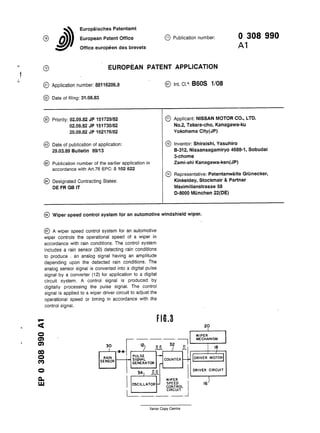
  • 1. Europaisches Patentamt European Patent Office Dffice europeen des brevets 5) Publication number. 0 3 0 8 9 9 0 EUROPEAN PATENT A P P L I C A T I O N © Application number: 88116206.9 © Date of filing: 31.08.83 nt. CI.4 B60S 1/08 §) Priority: 02.09.82 JP 151729/82 © Applicant: NISSAN MOTOR CO., LTD. 02.09.82 JP 151730/82 No.2, Takara-cho, Kanagawa-ku 20.09.82 JP 162176/82 Yokohama City(JP) S) Date of publication of application: © Inventor: Shiraishi, Yasuhiro 29.03.89 Bulletin 89/13 B-312, Nissansagamiryo 4688-1, Sobudai 3-chome S) Publication number of the earlier application in Zami-shi Kanagawa-ken(JP) accordance with Art.76 EPC: 0 102 622 © Representative: Patentanwalte Griinecker, £) Designated Contracting States: Kinkeldey, Stockmair & Partner DE FR GB IT Maximilianstrasse 58 D-8000 Munchen 22(DE) © Wiper speed control system for an automotive windshield wiper. © A wiper speed control system for an automotive wiper controls the operational speed of a wiper in accordance with rain conditions. The control system includes a rain sensor (30) detecting rain conditions to produce . an analog signal having an amplitude depending upon the detected rain conditions. The analog sensor signal is converted into a digital pulse signal by a converter (12) for application to a digital circuit system. A control signal is produced by digitally processing the pulse signal. The control signal is applied to a wiper driver circuit to adjust the operational speed or timing in accordance with the control signal. F I G . 3 Oi O) 00 o CO o Q_ UJ 30 R A I N SENSOR ) JUL 1 r rULofc SIGNAL G E N E R A T O R 34) JUL! 52 - L M E C H A N I S M JL OSCILLATOR J C O N T R O L | CIRCUIT U KIvert t V H _ M V ^ n j univcn winwui i IO —I xerox uopy centre
  • 2. :P 0 308 990 A1 I /VIPER SPEED CONTROL SYSTEM FOR AN AUTOMOTIVE WINDSHIELD WIPER 3ACKGROUND OF THE INVENTION The present invention relates generally to a wiper control system for an automotive windshield viper, which automatically controls the operating speed of the wiper in dependence upon rain con- iitions. More particularly, the invention relates to a wiper control system which can avoid the influence D f external conditions on detection of rain con- jitions. Published Japanese Utility Model Application No. 57-130747. published on August 14, 1982 dis- poses an automatic control system for an auto- motive wiper. The automatic control system in- cudes a vibration pick-up which detects vibrations D f the front window pane created by the impact of -ain drops. The output signal of the vibration pick- jp is amplified, filtered and then compared with a threshold to produce a driver signal when the out- put signal level exceeds the threshold level. In this wiper control system, since the com- parator compares an analog vibration pick-up out- put with an analog threshold, and since the am- plifier, filter and comparator all perform analog pro- cessing, they are apt to be influenced by external conditions such as errors in the operational char- acteristics of the respective circuit elements, or temperature conditions. These influences may cause the wiper operation to be deviated from that required. SUMMARY OF THE INVENTION Therefore, it is an object of the present inven- tion to provide a wiper speed control system which satisfactorily and successfully avoids the influence of external conditions on detection of rain con- ditions. Another and more specific object of the present invention is to provide a wiper speed con- trol system, which performs digital processing to detect rain conditions and to control operation of the automotive wiper mechanism. To accomplish the foregoing and other objects, a wiper speed control system according to the present invention includes a control circuit which can convert an analog rain sensor signal into a pulse signal suitable for digital processing. In prac- tice, the pulses of the pulse signal are counted and compared with a predetermined threshold value to produce a driver signal when the counter value becomes equal to the predetermined threshold val- ue. By controlling the wiper operation according to the digitally processed rain condition data, the in- fluence on detection of the rain conditions due to external conditions can be satisfactorily and suc- 5 cessfully avoided. According to one aspect of the invention, a wiper control system for an automotive wiper com- prises a ranin sensor for producing a sensor signal having a value indicative of rain conditions, means w for producing a digital rain-condition data signal according to the sensor signal value, means for producing a wiper control signal based on said • rain-condition data signal, and a wiper driver motor responsive to the wiper control signal to drive a 7 5 wiper at a rate variable in accordance with the wiper control signal. In another aspect, a wiper speed control sys- tem for an automotive wiper comprises a rain sen- sor including a vibrator with a sensor surface ex- 20 posed to rain and vibrating in accordance with rain conditions, the rain sensor producing a sensor sig- nal having an amplitude corresponding to the mag- nitude of vibration of the vibrator, a converter means for converting the sensor signal into a digi- 25 tal signal representative of the detected rain con- ditions, means for processing the digital signal to produce a driver signal, and a wiper driver motor responsive to the driver signal for driving a wind- shield wiper at a rate variable in accordance with 30 the driver signal. BRIEF DESCRIPTION OF THE DRAWINGS 35 The present invention will be understood more fully from the detailed description give below and from the accompanying drawings of the preferred embodiment of the invention, which, however, should not be taken to limit the invention to the 40 specific embodiment but for explanation and under- standing only. In the drawings: Fig. 1 is a schematic block diagram of the preferred embodiment of a wiper speed control 45 system according to the present invention; Fig. 2 is a sectional view of a rain sensor employed in the wiper speed control system of Fig. 1; Fig. 3 is schematic block diagram of a modi- 50 fication of the wiper speed control system of Fig. 1; Fig. 4 is a diagram illustrating location of a rain sensor on a vehicle with regard to dynamic air pressure;
  • 3. !P 0 308 990 A1 Fig. 5 is a diagram of application of the rain lensor to the wiper speed control system of Fig. 3; md Fig. 6 illustrates the vibration frequency ipectrum acting on the rain sensor. DESCRIPTION OF THE PREFERRED EMBODI- MENT Referring now to the drawings, particularly to =ig. 1, a wiper speed control system of the pre- :erred embodiment of the present invention gen- 3rally comprises a rain sensor 10 which detect rain ;onditions and produces a sensor signal having a /alue indicative of the detected rain conditions. The -ain sensor 10 is connected to a pulse signal generator 12 which is adapted to shape the sensor signal and to output a signal in the form of a train 3f pulses. The pulse train produced by the pulse signal generator 12 has a frequency corresponding to the sensor signal value and so indicating the detected rain conditions. The pulse train is fed to a counter 14. The counter 14 counts the pulses of the pulse train and produces a counter signal whenever the counter value reaches a predeter- mined value. The counter signal is fed to a driver circuit 16 including a driver motor 18 to drive a wiper mechanism 20. As shown in Fig. 2, the rain sensor 10 com- prises a vibration sensor having a sensor surface 102 inclined essentially parallel to the windshield 23 of a vehicle. The sensor surface 102 is formed on a vibrator panel 104 secured in a sensor hous- ing 106 in turn rigidly secured to a cowl top panel 22 near the windshield 23. A piezoelectric element 108 is secured to the inner surface of the vibrator panel 104 for vibration therewith. In this design, the rain sensor 10 detects vibra- tions produced by impact of rain drops on the sensor surface. That is, when rain falls, rain drops impinge on the sensor surface. Shock applied to the sensor surface and the vibrator panel 104 var- ies depending on the size of the colliding rain drop, its speed at impact and frequency of occurence of its collision. Therefore, the magnitude of vibration caused by impact of rain drops varies depending upon the size of the colliding rain drop, the colli- sion speed and frequency of occurence of its colli- sion. The piezoelectric element 108 vibrates with the vibrator panel and produces a sensor signal having a value corresponding to the magnitude of vibration. In summary, the sensor signal produced by the rain sensor in the manner set forth above is an analog signal, the output voltage of which varies in dependence upon the vibration amplitude of the vibrator panel and, in turn, in dependence upon xne rain conditions. The pulse signal generator 12 con- verts the analog signal into a pulse train suitable for digital processing for the purpose of wiper speed 5 control. The counter 14 is a digital counter for counting the pulses from the pulse signal generator 12 and internally compares the counter value with a predetermined threshold value to produce a counter signal when the counter value becomes w equal to the threshold value. When the wipers have been manually selected to operate intermittently, the counter signal can serve as a driver signal activating the driver circuit to operate the wiper mechanism 20. In this case, is the timing of occurrences of the counter signal corresponds to the interval between successive wiper operations, the frequency of which varies in dependence upon rain conditions. However, ac- cording to the shown embodiment it is also possi- 20 ble to control the wiper operational speed depend- ing upon the detected rain conditions, even in low- or high-speed continuous operation modes. In this case, wiper speed control may be performed by adjusting the voltage to be applied to the driver 25 motor 18 in accordance with the frequency of oc- currence of the counter signal. Fig. 3 shows a modification of the foregoing preferred embodiment of wiper speed control sys- tem according to the present invention. In this 30 modification, a rain sensor 30 is associated with the pulse signal generator 12. As in the foregoing pre- ferred embodiment, the rain sensor 30 produces an analog sensor signal having a value indicative of the rain conditions. The pulse signal generator 12 35 converts the analog sensor signal into a pulse train having a frequency corresponding to the sensor signal value. The pulse signal generator 12 is con- nected to a counter 32. The counter 32 is also connected to an oscillator 34 which is adapted to 40 output a pulse train with a constant frequency. The counter 32 counts the pulses from both the pulse signal generator 12 and the oscillator 34 and pro- duces a counter signal when the counter value, which represents the total number of pulses from 45 the pulse signal generator and the oscillator 34, become equal to the predetermined threshold. As shown in Figs. 4 and 5, the rain sensor 30 is mounted on the cowl top panel 22 of the vehicle body at a point subject to positive pressure from 50 the air stream, as indicated by hatched area in Fig. 4. If the rain sensor 30 is mounted on the vehicle body at a point subject to negative dynamic air pressure, the air pressure may adversely influence detection of rain conditions, since the angle of 55 incidence of the rain will be affected by the influ- ence of the air pressure. The sensor surface 302 of the rain sensor 30 is inclined at a given angle with respect to the hori- 3
  • 4. 3 EP 0 308 990 A1 :ontal plane such that the rear edge is higher than he front edge. The angle of inclination of the sensor surface with respect to horizontal plane is jmpirically selected to fall within the range of from 5° to 25°. Normally, rain drop speed is approxi- mately 1 m sec, to 15 m/sec. In this normal rain ;ondition, the selected inclination angle of the sen- sor surface, i.e. 5° to 25° is satisfactory for detect- ng rain condition under usual vehicle speed. Preferably, the rain sensor would be provided with a sensor surface which can be variably in- ;lined in dependence upon the rain drop speed. Dynamic air pressure reflecting vehicle speed may oe used as a detecting parameter to control the nclination angle of the sensor surface. As in the foregoing embodiment, the rain sen- sor 30 includes a vibrator panel 304 with a sensor surface 302 exposed by a sensor housing 306. The yibrator panel 304 engages the sensor housing 306 only at its circumferential edge so that it can s/ibrate in response to impact of rain drops on the sensor surface. A piezoelectric element 308 is se- cured to the vibrator panel 304 via an electrode 310 formed therebetween. Another electrode 312 is formed on the opposite surface of the piezoelectric element 308. The electrodes 310 and 312 are electrically connected to an amplifier 316. The am- plifier 316 is connected to the wiper speed control circuit, including the pulse signal generator 12, the counter 32 and the oscillator 34, to supply the sensor signal thereto. The natural or natural resonate frequency of the vibrator panel 304 is chosen to fall in the range of 10 KHz to 25 KHZ. This specific natural fre- quency of the vibrator panel is experimentarily se- lected to avoid the influence of vibrations created by the vehicle horn or other equipment or engine vibrations. Fig. 6 shows the vibration frequency spectrum created by vehicle horn and received by the rain sensor. As will be appreciated from Fig. 6, the maximum frequency of vibration created by the vehicle horn is approximately 9 KHz. Therefore, by selecting the natural frequency of the vibrator panel 304 in the given range, i.e., 10 KHz to 25 KHz, the influence of the vehicle horn upon detection of the rain conditions can be satisfactorily avoided. The maximum natural frequency of the vibrator panel 304 is selected in view of the amplitude of the sensor signal. To achieve a natural resonant frequency of the vibrator panel 304 beyond 25 KHz, the vibrator panel has to be adequately thick in relation to the area of the sensor surface. In this case, the amplitude of vibration produced by im- pact of rain drops onto the sensor surface will be too low to be used in the wiper control system. That is, by setting the natural frequency of the vibrator panel so high, the sensivity to rain will be lowered, thereby degrading the response charac- teristics of the wiper control system. In this modification, since the counter signal is produced when the total number of pulses from both the pulse signal generator and the oscillator 5 reaches the predetermined threshold, the wiper mechanism can be driven at the longest interval in intermittent operational mode or at the lowest speed in continuous operational mode, as defined by pulse period of the pulse train from the oscilla- o tor. As a result, the wiper mechanism will continue to operate even when the vehicle passes through a tunnel in which rain drop cannot be detected. This will be advantageous for providing clear vision for the driver. 7 5 It should be noted that the sensor surface subjected to rain should be larger than 100 mm2 in area in accordance with experimental results. In experimental tests, it was found that a rain drop impinging on a plane surface usually expands to an 20 area of approximately 100 mm2. It is necessary to provide a sensor surface sufficiently large to re- ceive the full volume of rain water upon impact in order to detect the rain conditions. Otherwise, a plurality of rain sensors, each of which has a sen- 25 sor surface area of less than 100 mm2, can be used so that the total contiguous area of the sensor surface exceeds 100 mm2. As set forth above, according to the present invention, an analog sensor signal is converted into 30 a pulse train so that the influence of errors in the circuit element characteristics, temperature condi- tions and so forth can be avoided. 35 Claims 1. An intermittent timing control system for a wiper system of a vehicle, comprising : a rain sensor (30) for monitoring rain condition to 40 produce a rain condition indicative sensor signal, a control signal generator means (12, 32, 34) for generating a wiper control signal on the basis of said sensor signal and a wiper driver motor (18) responsive to the control signal for driving a wind- 45 shield wiper (20) at variable intervals in an intermit- tent mode of operation. CHARACTERIZED IN THAT said rain sensor (30) having a vibrator (304) adapted to oscillate at an amplitude and frequency depending upon the rate so of rain, said vibrator (304) having one surface (302) exposed outwardly of said vehicle so that raindrops directly collide with said one surface (302) for causing oscillation of said vibrator (304), said one surface (302) of said sensor (30) being mounted on 55 a point on a body of said vehicle subject to positive pressure from an air stream travelling over said vehicle and said vibrator (304) producing said sen- sor signal having an amplitude and frequency cor- 4
  • 5. 7 EP 0 308 990 A I a ssponding to the magnitude of vibration and fre- uency of said one surface (302) ; and aid means (12, 32, 34) is responsive to the mag- itude and frequency of said sensor signal for eriving an intermittent timing signal for wiper inter- 5 littent operation based on the sensor signal value. 2. The control system as set forth in claim 1 /herein said one surface (302) of said rain sensor 30) has an area greater than 100 mm2. 3. The control system as set forth in claim 1 or w : wherein said one surface (302) of said rain sen- or (30) is inclined at an angle relative to the lorizontal. 4. The control system as set forth in claim 3 therein said angle is in the range of 5 degrees to 15 !5 degrees. 5. The control system as set forth in claim 4 /herein said angle is variable in dependence on ain drop speed. 6. The control system as set forth in any of 20 :laims 1 to 5, wherein said one surface (302) is nounted on a cowl top panel (22) of said vehicle. to J 0
  • 6. EP 0 308 990 A1 F I G . 1 12 w w | r a i n EHk?.1: S E N S O R S I G N A L b h N b U K G E N E R A T O R WIPER S P E E D CONTROL C I R C U I T 2 0 z W I P E R M E C H A N I S M ,18 1 1 DRIVER M O T O R DRIVER C I R C U I T 7
  • 7. EP 0 308 990 A1 F I G . 3 I2> J U L 3 2 J l P U L S E SIGNAL C O U N T E R G E N E R A T O R — 3 4 ) J U L ! 1 O S C I L L A T O R W I P E R S P E E D C O N T R O L C I R C U I T 2 0 I W I P E R M E C H A N I S M 8 i / DRIVER M O T O R DRIVER C I R C U I T F I G . 4
  • 8. EP 0 308 990 A1 F I G . 6
  • 9. European Patent Office EUROPEAN SEARCH R E P O R T Application Number EP 88 11 6206 DOCUMENTS CONSIDERED TO BE RELEVANT Category Citation of document with indication, where appropriate, of relevant passages Relevant to claim CLASSIFICATION OF THL APPLICATION (Int. CI.4) Y A X FUNKSCHAU /ol. 50, no. 19, September 1978, DE, pages 103-104; K.-H. SCHMIDT: "Automati sche Schei benwi scher steuerung" * column 4, line 59 - column 6, l i n e 33; figure 3 * DE-U-7 005 022 (STEGER) * page 1, lines 19-23; claim 2 * PATENT ABSTRACTS OF JAPAN /ol. 4, no. 105 (M-23) (587) 26th J u l y 1980; & JP - A - 55 063 941 (JEKO) 14-05-1980 DE-A-2 523 111 (0HE) * page 3, line 25 - page 4, line 23 * The present search report has been drawn up for all claims 1,3,6 B 60 S 1/08 1 , 3 , 6 4 1 1-3 TECHNICAL HELUS SEARCHED (Int. C1.4) B 60 S 1/00 Placeofsearch BERLIN Dateofcompletionofthesearch 12-12-1988 & x a m i n e r STANDRING M A CATEGORY OFCITED DOCUMENTS X: particularly relevant if taken alone Y: particularly relevant if combined with another document ofthe same category A: technological background O: non-written disclosure P : intermediate document T: theory or principle underlying the invention E: earlier patent document, but published on, or after the filing date D: document cited in the application L: document cited for other reasons &: member ofthe same patent family, corresponding document