1. Modified Polysulfone Nanofiltration Membrane Synthesis for Hydraulic Fracturing Water
Recycle
A thesis submitted in partial fulfillment
of the requirements for the degree of
Master of Science in Chemical Engineering
By
Blake Johnson
University of Arkansas
Bachelor of Science in Chemical Engineering, 2014
December 2015
University of Arkansas
This thesis is approved for recommendation to the Graduate Council.
______________________________
Professor Jamie Hestekin, Ph.D.
Thesis Director
______________________________ ______________________________
Professor Ranil Wickramasinghe, Ph.D. Professor Robert Beitle, Ph.D.
Committee Member Committee Member
2. Abstract
The use of hydraulic fracturing has resulted in significant increases in the yield of oil and natural
gas, as water pumped into wells at high pressure cracks the formations and releases the
hydrocarbons that are locked in the rocks. This process has created large volumes of brackish
water that is very difficult to process and is often disposed of into injection wells. Suspended
solids and some dissolved solids are more readily removed, but the multivalent ions found in
certain salts can precipitate in a well and complicate the reuse of flowback in future hydraulic
fracturing operations.
Nanofiltration, a membrane separation technique, has the potential to remove these salts at a
much lower cost than desalination techniques such as reverse osmosis. Secondary interactions,
such as charge, can be added through functional groups to increase the rejection of the positive
ions and allow for the reuse of flowback in operations where low quality water is acceptable.
To produce these membranes, polysulfone was reacted with trimethylchlorosilane and
trimethylamine to produce a positively charged functional groups that would allow for selective
rejection of ions. While the two-step reaction to produce these functional polymers was
successful, the polymer created did not have the properties required to produce a membrane.
The positively charged polysulfone had functional groups that made it soluble in water, and
membranes cast from this polymer readily swelled and deformed when exposed to most fluids,
including water and air. While some characteristics of these membranes, such as pore diameter,
were comparable to commercial membranes, the solubility characteristics made filtration testing
impossible. However, while the final positively charged polymer was unusable, the functional
precursor polymer was successfully synthesized and can be used with other methods to produce
the positively charged polymers.
3. Acknowledgements:
I would like to offer my sincere gratitude to my advisor, Dr. Jamie Hestekin. Without your
assistance and support, I would not have been able to proceed through this project and complete
my thesis.
I would also like to thank all those inside and outside of the department who have assisted me
throughout my experimentation. I would like to begin with Brian Walker and Dr. Matthew
McIntoch from the Chemistry Department, without whom I would not have been able to perform
and refine the chloromethylation of polysulfone. I want to thank Dr. Dmytro Dmydov and
Brigitte Rodgers for working with me in learning about filtration testing and Atomic Absorption;
Haley Cleous and Alex Moix for their assistance in learning and running evapoporometry; Long
Tran for his research in the filtration of flowback water using commercial membranes; George
Marshall for working with the membrane filtration units; Kevin Roberts for his assistance with
FTIR and SEM, as well as his and Dr. Tammy Rechtin’s insight into improving the process.
Without the help of these people, I would not have been able to progress at this pace with my
research or complete my thesis.
Also, I’d like to give a special thanks to the Flexible Water Solution for their financial support
and Solvay for the polysulfone polymer required for this research.
Finally, I’d like to thank my committee members, Dr. Ranil Wickramasinghe and Dr. Robert
Beitle for their time and willingness to serve on my defense committee.
It gave me great pleasure to be able to work alongside everyone.
6. 1
1. Introduction:
As the demand for energy in the form of oil and natural gas rises, the use of technologies that
increase the yield of these hydrocarbons rises as well. Hydraulic fracturing is a widespread
technology that relies on pressurized water to open and thereby increase the accessibility of oil
and natural gas from wells.1
Water mixed with additives to stabilize the fluid and hold open the
fracture is pumped at high pressure into a drilled well. This cracks the formation and allows the
hydrocarbons that are locked inside shale formations to be pumped out.
Hydraulic fracturing is highly water-intensive however, as each well requires upwards of 1
million gallons to fracture a vertical well, and 3-6 million gallons to fracture a horizontal well on
average, though larger amounts can be necessary.2
Only a small fraction of this water is
recovered, and between 70-90% of the water used in a hydraulic fracturing operation is lost to
the formations.2
Only 10-30% of the water is recovered as flowback water, but this flowback is
highly contaminated, both from the chemicals and additives put into the water in order to keep
the formations open after fracturing, shown in Table 1, and from the compounds retained when
the formation is opened, shown in Table 2.3
7. 2
Table 1: Additives used in fracturing fluid, examples, and their primary purpose.3,4
Constituent Composition
(% by vol)
Example Purpose Often
used
Water and
sand
99.5 Sand suspension “Proppant” sand grains hold
microfractures open
Yes
Acid 0.123 Hydrochloric or
muriatic acid
Dissolves minerals and initiates
cracks in the rock
No
Friction
reducer
0.088 Polyacrylamide or
mineral oil
Minimizes friction between fluid
and the pipe
Yes
Surfactant 0.085 Isopropanol Increases the viscosity of the
fracture fluid
No
Salt 0.06 Potassium chloride Creates a brine carrier fluid No
Scale
inhibitor
0.043 Ethylene glycol Controls precipitation and prevents
scale deposits in pipes
Yes
pH-adjusting
agent
0.011 Sodium or
potassium
carbonate
Maintains effectiveness of
chemicals additives
No
Iron control 0.004 Citric acid Prevents precipitation of metal
oxides
No
Corrosion
inhibitor
0.002 n,n-dimethyl
formamide
Prevents pipe corrosion No
Biocide 0.001 Glutaraldehyde,
hydrogen sulfide
Minimizes growth of bacteria that
produce corrosive, toxic or
contaminating by-products
Yes
Table 2: Initial concentration range and concentration after 14 days of constituents of flowback
water from shale gas formations.3,5,6
Constituent Initial Concentration (mg/L) Concentration at 14 days (mg/L)
Total dissolved solids 66,000-261,000 3,010-261,000
Total suspended solids 27-3,200 17-1,150
Hardness (as CaCO3) 9,100-55,000 630-95,000
Alkalinity (as CaCO3) 200-1,100 26.1-121
Chloride 32,000-148,000 1,670-181,000
Sulfate ND-500 ND-89.3
Sodium 18,000-44,000 26,900-95,900
Calcium 3,000-31,000 204-14,800
Strontium 1,400-6,800 163-3,580
Barium 23,000-4,700 43.9-13,600
Bromide 720-1,600 15.8-1,600
Iron 25-55 13.8-242
Manganese 3-7 1.76-18.6
Oil and grease 10-260 4.6-103
8. 3
The disposal of flowback water is a major environmental concern, as the total volume of
flowback water recovered from hydraulic fracturing is sharply growing. The only current means
of disposal is pumping the waste water into injection wells. Estimates show that between 2010
and 2011, disposal of water into injection wells in Ohio increased from 26 million gallons to 106
million gallons.7
Disposing of flowback water in this way is cost inefficient and is a waste of a
valuable resource. Dumping flowback water into a Class II Injection Well costs between $1.50-
$2.00/barrel, and transporting that water to a well can cost up to $4.00/barrel, depending on the
proximity of the drilled well to a usable injection well.2
These estimates combined with the
volume of water injected into Ohio wells in 2011 results in a cost of over $15 million to dispose
of flowback water.
Other environmental concerns are present as well. Concerns have been raised on whether the use
of injection wells to dispose of flowback water can cause groundwater contamination and reduce
the supply of drinking water.8
Geological surveys have also attributed disposal of water into
injection wells to earthquakes, and more than a dozen of these earthquakes were reported in Ohio
and linked to the injection of water into wells.7
Flowback from hydraulic fracturing cannot be reused for any purpose without first being filtered
to remove the components present inside of the water. Various methods are available in order to
remove the additives, dissolved solids, and suspended solids, which include coagulation,
flocculation, and membrane filtration through ultrafiltration (UF) and nanofiltration (NF).
However, these methods at present are not efficient in removing the salts present in flowback.
Desalination is required in order to remove divalent salts, which can precipitate when exposed to
sulfates and cause scaling in the well, preventing the formation from fracturing properly.2
9. 4
This research paper was made to investigate a method of removing divalent salts from a salt
water flowback solution using nanofiltration. A method was found in order to modify
polysulfone polymer to give it a positive charge, which will allow for greater rejection of
positively charged ions found in salt water. Methods to produce this modified polymer were
investigated, and after characterization of the polymer, filtration tests were performed on ideal
solutions and collected flowback samples.
10. 5
2. Literature Review:
2.1. Hydraulic Fracturing:
Hydraulic fracturing is a process used to increase the recovery of oil and natural gas from drilled
formations.9
After an oil or gas well is drilled and cased, holes are shot into the casing at set
intervals to reopen the casing and allow access to the formation.4
Water is pumped into the well
at high pressures of 480 to 680 bar to crack open the formation, increasing the flow of oil or gas
from the undrilled portions of the well.10-12
In order to hold the formations open, sand and
chemical additives, listed in Table 1, are added to the water to aid in the fracturing and prevent
the formation from closing after the water is withdrawn.1
For a hydraulic fracturing operation to successfully open a formation, large quantities of water
are required, ranging from 2 million to 13 million gallons.13
A portion of this water is lost to
formation that was fractured, and the quantity returned to the surface is highly dependent on the
shale type being drilled. The water that is recovered is highly contaminated and cannot be reused
without treatment. A small percentage of recovered water, or flowback, is treated and recycled
for other industrial applications, but 90% of the flowback is disposed of into injection wells.14
On a national scale, the water required for hydraulic fracturing is small when compared to other
technologies that use freshwater. While a well requires anywhere from 8,000 to 100,000 m3
to
perform a fracture, the water used for hydraulic fracturing is dwarfed by the cooling water
requirements for thermoelectric power.13
An estimated 40% of the national yearly freshwater
withdrawal is used for cooling in thermoelectric power generation (278 billion m3
), and 10% of
this water is lost due to evaporation (27.8 billion m3
). Over the last decade, hydraulic fracturing
has required only 1% (300 million m3
) of the water loss from evaporation to fracture 20,000
wells with an average water usage of 15,000 m3
per well.
11. 6
While this is a small percentage on a national scale, locally it causes water resource conflict in
drought prone states, including Texas and Pennsylvania.9
In the 2011 drought in Texas, supply of
water for hydraulic fracturing nearly ceased, and natural gas companies attempted to buy their
supply from farmers, creating a conflict for water usage to produce food. In the same year,
Pennsylvania temporarily suspended 11 permits to natural gas companies to use water from the
Susquehanna River Basin for use in hydraulic fracturing, due to the drought decreasing water
levels in the basin. The ability to reuse flowback for hydraulic fracturing would have reduced
pressure from freshwater sources in times of drought, and would have allowed for continued
operations, albeit limited.
2.2. Shale Formation:
Oil and natural gas is produced from shale formations that are rich in organic compounds such as
hydrocarbons, namely oil and natural gas.15
However, due to the non-porous nature of shale, the
organic compounds locked in the formations cannot be removed without opening the formations.
The widespread use of hydraulic fracturing drastically increased the drilling of shale for oil and
natural gas, resulting in production of natural gas from shale increasing from 2% in 2000 to 23%
in 2010, and an accessible yield increase from 58.3 billion m3
to 13.8 trillion m3
.11,15
This
increase in shale production has caused a surge is water usage for hydraulic fracturing, and as a
result an increase in flowback produced.
The volume of water required to fracture a well, as well as the water recovered, is dependent on
the shale play that the well is drilled to. Three of the main sources of natural gas shale—
Marcellus Shale, Barnett Shale, and Haynesville Shale—have been investigated as to their water
requirements to fracture a well, and the flowback recovered from the hydraulic fracturing, which
are outlined in Table 3.14
12. 7
Table 3: Water required fracturing a well and water recovered from three of the major natural gas
shale formations.13,14
Shale Play Production
Contribution
Water Needed to
Fracture
Water Recovered TDS (mg/L)
Marcellus 29% 5.6 million gallons 25% 180,000
Haynesville 23% 5.6 million gallons 34% 110,000
Barnett 17% 4.0 million gallons 35% 60,000
As well as the water requirements, the amount of total dissolved solids (TDS) in flowback is
highly dependent on the shale type being fractured. The concentration of TDS can range from
near seawater levels of 25,000 mg/L, such as flowback found in Fayetteville Shale, to 180,000
mg/L found in Marcellus Shale.13
This large variation, as well as the high TDS concentrations
found in some shale, makes treatment of flowback difficult.
2.3. Flowback:
While the disposal of flowback is now heavily regulated by the EPA, improper disposal of
flowback led to several environmental hazards before regulations were put in place.16
Before
2010, several sites of flowback disposal lead to environmental contamination, and both ground
water and drinking water were polluted with flowback contaminants.17
After regulations were
put in place in 2010, several EPA investigations in Pennsylvania and Texas revealed that tap
water was polluted with benzene, a known carcinogen, and flammable concentrations of
methane.16,17
Currently, flowback is pumped into Class II injection disposal wells as the main method of
disposal.18
This method of disposal requires little to no treatment and results in a very low risk of
contamination if proper methods are used.5
This method is also very wasteful, as the water that is
injected can no longer be recycled or reused. It’s estimated that 106 million gallons of flowback
was disposed of into Ohio injection wells in 2011 alone.7
For dry regions such as Texas and
13. 8
California, this water is a precious resource and being able to reuse it would alleviate some
pressure of currently scarce water resources.
Unfortunately, due to the high levels of contamination in flowback, reuse of this water is
impossible without treatment. Water that is recovered from hydraulic fracturing operations is
contaminated with hydrocarbons, organic compounds, and salts as outlined in Table 2,3,5,6
as well
as toxicant-producing microbes.1,19
While it is not economically feasible to remove enough
contaminants to produce drinkable or dischargeable water, it can be treated to a degree and
reused in another hydraulic fracturing operation.3
Many of these contaminants, including the hydrocarbons and organics, can be removed with
conventional and developed treatment methods such as microfiltration, ultrafiltration, and
chemicals.20
Additionally, salts at lower concentrations could be economically removed through
reverse osmosis.21
However, the salt concentrations that are typically present cannot be removed economically
through reverse osmosis.22
To reuse this water for further hydraulic fracturing, multivalent salts,
such as calcium, must be removed, as they can precipitate much more readily than sodium and
cause scaling and blockages in wells, reducing flow through pipes and reducing the opening of
formations.2,11
2.4. Membrane Filtration:
Membrane separations are processes that use a membrane film in order to filter out different
species from a liquid solution.23
The species that are separated with membranes are determined
by the pore diameter, membrane thickness, and the materials that the membrane is made of.
Typical membrane separations include microfiltration, ultrafiltration, nanofiltration, and reverse
osmosis, with forward osmosis becoming more widespread. Microfiltration and ultrafiltration are
14. 9
able to remove suspended and dissolved solids from a solution, while nanofiltration, reverse
osmosis and forward osmosis are able to filter ions and nanoparticles from liquids.24,25
Non-
membrane methods of filtering salt water are available, but a comparison will be made between
reverse osmosis, forward osmosis, and nanofiltration.
2.4.1. Reverse Osmosis:
Reverse osmosis is a high pressure membrane separation technique that uses pressure and a
concentration gradient to remove, or reject, salt ions from a salt water solution.24
Reverse
osmosis membranes use their web-like structure to filter water, forcing water molecules to
navigate the fibrous layers and preventing dissolved solids and salts from passing through, or
permeating, the membrane.26
The rejection of salt through reverse osmosis is dependent on the
pressure applied to the feed and the salt concentration.27
A significant drawback of reverse osmosis is fouling—the buildup of dissolved and suspended
solids in the membrane—hindering the flux of water.28
This fouling can be reduced through
pretreatment with microfiltration and ultrafiltration to remove suspended solids. However, these
processes are not suited for removing dissolved solids, and fouling can still occur due to the high
salt concentrations.
To reduce fouling, reverse osmosis membranes can also be treated with polymers to prevent the
buildup of suspended solids. Several research groups have coated commercial reverse osmosis
membranes with polydopamine to make the surface hydrophilic and remove surface charges,
reducing the tendency for suspended solids to attach to the membrane.29
These methods helped
to reduce the fouling of membranes with minimal effect on the water flux or salt rejection as
compared to the manufacturer specifications. However, this study did not perform an economic
15. 10
analysis on the filtration, and it is unknown if the process was economically viable based on the
data presented.
The methods of combined filtration have been tested for the filtration of flowback using a
coupled ultrafiltration and reverse osmosis system. A pilot study conducted compared two
systems with ultrafiltration coupled with reverse osmosis, one using commercial membranes and
the other using a polydopamine and PEG coating on both the ultrafiltration and reverse osmosis
membranes.2
Fouling of the reverse osmosis membrane was significantly reduced in both
systems, and salt rejection was increased in the system with the polydopamine coating. The
uncoated membranes reduced calcium concentrations from 3,790 mg/L to 59 mg/L (98.5%
rejection) and coated membranes reduced concentrations from 3,790 mg/L to 2 mg/L (99.9%
rejection). However, this study did not conduct an economic analysis, so it is unknown if this
process was economical. This study also tested the minimum concentration of calcium seen in
flowback (near 3,000 mg/L), as opposed to using a value closer to the maximum 30,000 mg/L,
resulting in a low osmotic pressure of 2,500 kPa (25 bar). An economic analysis using this
osmotic pressure would not be representative of a real-world flowback filtration.
Another drawback is that, while filtration through reverse osmosis would desalinate the water
and remove the multivalent ions, the pressure required to filter the salts to a low concentration is
too great to be commercially viable. This is due to the high concentration of monovalent ions
that are present in the solution, which increases the osmotic pressure to filter the ions.3
Reverse
osmosis membranes require a pressure of 15-25 bar to filter brackish water, which has a salt
concentration of 1000-5000 ppm, but the required pressure increases to 40-80 bar to filter
seawater at a concentration of 35,000 ppm.23
The amount of salt present in flowback water can
be up to 44,000 ppm sodium and 31,000 ppm calcium.3
16. 11
Although limited on flowback treatment through reverse osmosis have been published, efforts
have been made to use reverse osmosis to treat flowback water that show it can be an economic
process.30
The pilot unit tested in a previous study was able to filter flowback water at a cost of
$1.25/barrel, considerably lower than the transportation and disposal cost which averages
$6/barrel, estimated to be a net savings of $253,000/well. However, this study used low
concentrations of total dissolved solids, 55,000 mg/L for a blend of flowback and produced
water, where an average well would have a considerably higher concentration of total dissolved
solids, ranging from 66,000 to 261,000 mg/L.3
For these applications, other processes are more
reasonable, such as forward osmosis.31
2.4.2. Forward Osmosis
Forward osmosis is a membrane separation technique that, unlike pressure-driven processes such
as reverse osmosis and nanofiltration, relies on the principle of direct osmosis to facilitate
transport across a membrane.25
Direct osmosis is the drive for the TDS concentration on each
side of a membrane to equalize by transporting water across the membrane to dilute the higher
concentration side.31,32
A typical forward osmosis relies only on the osmotic pressure difference, defined by the
difference in concentration of the feed and draw solution, to facilitate transport across a
semipermeable membrane that is similar to that of a reverse osmosis membrane.33
This poses
several problems for forward osmosis filtration.
While forward osmosis is not an energy intensive process when compared to pressure filtration
techniques, it results in a low transport of water across a membrane.34
This is due to the fact that
the draw solution needs to have a considerably higher osmotic pressure than the feed solution.
This can be achieved in two ways: the osmotic pressure of the draw solution can be increased by
17. 12
adding salt or dissolved solids, or the feed solution can be diluted to decrease the concentration
of solids.35
This as well carries the disadvantage that the draw solution has to be treated to
remove the salt added to facilitate the transport of water.25
To compensate for this disadvantage, the draw solution can be composed of an easily removable
salt solution, such as volatile solvents or perceptible salts.36
When the volatile solvent, such as
sulfur dioxide, is added to the draw solution, the osmotic pressure can be increased past the
osmotic pressure of the feed solution. Once the osmotic pressure difference nears zero, the draw
solution can be mildly heated to separate the volatile solvent by returning it to a gas state.
Afterwards, the volatile solvent can be re-added to the upstream draw solution to continue
transport across the membrane.
This process can also be conducted by using precipitable salts, such as aluminum sulfate.36
In
this process, the salt is mixed into the draw solution to increase the osmotic pressure. After the
dilution is carried out, the draw solution is treated with a precipitating agent complimentary to
the precipitable salt. This process can require considerable treatment though, as any leftover
precipitating agent must be removed as well.
For low-salinity operations where the removal of water to purify the feed solution is the desired
outcome, or to purify the water for environmental ejection, sodium chloride solutions are often
used as the draw solution.37,38
Potassium chloride has also shown to be an effective draw for
these purposes, as it is more easily removed than sodium chloride.39
However, studies testing
these draw solutions have used feed solutions with TDS less than 7,000 mg/L and have the goal
of removing oil and acids as opposed to ions.39,40
For the purposes of removing salt from
flowback, this process is not ideal.
18. 13
For high-salinity operations, including the treatment of flowback, a volatile solution of ammonia
and carbon dioxide creates an ideal draw solution.36,37,41,42
By mixing water with soluble
ammonium bicarbonate, a high-salinity solution is created with a high osmotic efficiency,
meaning that small concentrations are required to increase the osmotic pressure.37
The osmotic
efficiency allows for high water recovery; a 1.5 M solution can produce an osmotic pressure of
50 bar, which can recover 50% of water from seawater, and a 3 M solution will produce 100 bar
of osmotic pressure for a 75% water recovery.36
Once the draw is diluted, the solution only needs
to be heated to 60o
C to convert the ammonium bicarbonate to ammonia and carbon dioxide,
allowing it to evaporate from solution and be recycled in the draw upstream.36
By treating water
using this solution, a water recovery of 60% can be obtained while reducing the TDS from
70,000 mg/L to dischargeable levels of less than 500 mg/L.37,41
The process to remove the
ammonia and carbon dioxide is energy efficient as well, requiring 275 kWhrth/m3
to heat the
water to 60o
C, which is 57% less energy than would be required to evaporate the water for
filtration.41
An efficient means of heating the draw solution is using the heat from flared gas.43
By utilizing
the waste heat from flaring, the required energy input can be greatly reduced, allowing for an
efficient separation or allowing the use of higher ammonium bicarbonate solutions to increase
water recovery.
One of the advantages of forward osmosis over reverse osmosis is the reduction in membrane
fouling. In a reverse osmosis system, the applied pressure drives the suspended and dissolved
solids into the membrane, whereas in forward osmosis systems the water alone is drawn towards
the membrane, resulting in minimal interaction of the dissolved and suspended solids with the
membrane.28,32
19. 14
Hybrid reverse osmosis and forward osmosis systems, known as pressure-assisted forward
osmosis, have been tested to treat flowback water.34
In this system, a forward osmosis system is
combined with a low to medium pressure pump to increase the flux across the membrane. The
addition of pressure to the transport mechanism reduces the required osmotic pressure difference
at the drawback of increased energy costs. The unit tested increased the water flux by 22% after
a pressure of 10 bar was applied, and reduced the total dissolved solid concentration to 200
mg/L.
2.4.3. Ultrafiltration:
Ultrafiltration is a membrane separation technique that uses size-exclusion to filter materials
from a liquid solution.23
Ultrafiltration membranes require a low pressure, 1-10 bar, to perform a
separation, making them an effective means of removing dissolved and suspended solids from a
solution.
Ultrafiltration membranes have pores that range from 1-100 nm to filter materials such as
suspended solids and microsolutes. While the pore diameter of these membranes can reach close
to 1 nm, the species separated must have a considerably lower molecular weight, at least ten
times smaller, than the species being retained.23
This makes the membranes ideal for the removal
of chemical additives and solids present in flowback, but not reasonable for the removal of
calcium from sodium, which have a much narrower difference in molecular weight.
2.4.4. Nanofiltration:
Nanofiltration is a membrane separation process that lies between ultrafiltration and reverse
osmosis in its separation abilities.44,45
It is a salt separation technique that relies an open network
structure to separate the ions, as opposed to the homogeneous structure of reverse osmosis.
20. 15
The pore diameter distribution of nanofiltration membranes is typically less than 2 nm, which is
considerably smaller than the pore diameters of ultrafiltration membranes.23
While the reduction
in pore diameter allows for the separation of smaller particles and ions, nanofiltration membranes
use surface properties such as the presence of charged groups to increase separation of ions and
compounds with different characteristics.46,47
For applications in desalination, nanofiltration membranes have the ability to selectively filter
different ions in a salt solution, resulting in a higher rejection of multivalent ions than
monovalent ions in a salt water solution.48
This separation of multivalent salts attracted interest
towards use in frack water filtration to remove precipitable ions for flowback reuse.
While reverse osmosis can potentially conduct a complete separation, nanofiltration can instead
be used in order to carry out the filtration at a considerable lower osmotic pressure, as the
membrane will be removing the multivalent ions and a smaller fraction of the monovalent ions.49
This selectivity reduces the pressure required to filter seawater from the 40-80 bar required for
reverse osmosis to 10-25 bar.23
While this separation can’t produce drinking water, as a large
concentration of monovalent ions will still be present, the reduction of multivalent ions is large
enough that salt water can be filtered and reused for other applications, including hydraulic
fracturing.
Commercial nanofiltration membranes, unfortunately, are not suited for the high rejection of
multivalent ions necessary for flowback reuse. As shown in research conducted by Haley Cleous,
commercial membranes, namely NF3A and others produced by Sepro Membranes, could
selectively reject divalent calcium ions to 69.8% while only rejecting 4% of monovalent sodium
ions with 16,000 mg/L of calcium in solution. However, this separation was inadequate, and the
21. 16
commercial membranes could not achieve a 90% rejection and reduce the calcium concentration
to below 2,000 mg/L, the concentration required for reuse in hydraulic fracturing.
Titration testing of these membranes showed that most of the membranes contained a negligible
charge, and others contained small charges. The quantifiable charges detected on these
membranes were predominantly negative charges, which corresponds with previous observations
that most commercial membranes are either uncharged or negatively charged.48
Uncharged membranes rely on sieving based on pore diameter to filter ions and particles, but the
lack of charge and, by extension, the exclusion of Donnan (electrical) effects reduced the
effectiveness of the separation of charged ions.45,50
Nanofiltration membranes can conduct a separation using both sieving and Donnan effects,
allowing for more selective separations than those based on molecular weight. A novel
membrane with an added positive charge could to be used in order to achieve the desired
selective rejection of multivalent positively charged ions. The positively charged membrane
would have an increased repulsion of positive ions based on the strength of the charge due to the
Donnan exclusion mechanism, the separation resulting from electrostatic interactions of similarly
charged membranes and ions.51
This increased repulsion would allow for the desired rejection of
multivalent ions, as divalent and multivalent positively charged ions would receive a stronger
repulsion to the membrane than the weaker-charged monovalent ions.
Producing a positive charge on a nanofiltration membrane can be performed through several
mechanisms: addition of functional groups, adsorption of ions in the membrane structure, and
adsorption of charged molecules.52
Of interest to this research project was the production of a
permanent positive charge on a membrane through the addition of functional groups. This
method, unlike adsorption of ions or charged molecules, results in a stable charge that will not be
22. 17
reduced over time, resulting in a longer-lasting membrane functionality. To produce these
charged membranes, the polymer polysulfone was selected for modification by the additional of
functional groups.
2.5. Polysulfone:
While commonly used to create ultrafiltration membranes, polysulfone is a widely used polymer
for membrane synthesis. Polysulfone is an ideal membrane polymer due to its glass transition
temperature of 185-195o
C, high pH resistance for both acids and alkalis, and thermal stability,
being resistant to hydrolysis in both hot water and steam.53,54
Membranes produced with
polysulfone are highly durable due to the high mechanical properties, including tensile strength
and tensile impact, compared to other amorphous thermoplastics.53
Of interest for the production
of novel polymers, polysulfone has the ability to be reacted to produce a variety of functional
groups. These reactions include chloromethylation, sulfonation, metalation, and
quaternization.55,56
The primary reaction of interest to this study is the chloromethylation of polysulfone to add
functional chloromethyl groups to the polysulfone monomer, shown in Error! Reference source
ot found.. The chloromethylation of polysulfone has been researched considerably for its
applicability as a precursor for a wide variety of processes, including functional membranes,
coatings, and selectively permeable films.57
Chloromethylated polysulfone possesses a high
chemical stability and retains the physical properties of polysulfone, making it an ideal modified
polymer.57,58
However, many studies have reported varied procedures and conflicting results, and it is
necessary to determine the correct operating procedure and conditions to produce the best
polymer.
23. 18
This chloromethyl group can be reacted with other compounds through a substitution
nucleophilic (SN2) reaction, the replacement of chlorine with a strong nucleophile, to form more
specific functional groups. Reacting the polymer with trimethylamine, the selected nucleophile,
produces a functional group with a positive charge, allowing for higher rejection of positively
charged groups.
24. 19
3. Experimental Methods and Procedure:
The goal of this study is to separate multivalent ions from a salt water frack water solution, while
retaining monovalent ions. This was accomplished by producing a polysulfone polymer that held
a charge than could increase the selectivity of ions based on their charge. The modification was
conducted by performing a chloromethylation reaction on polysulfone polymer, using
paraformaldehyde and trimethylchlorosilane as the chloromethylating agent and stannic chloride
as the catalyst. Amination of the chloromethylated polysulfone used trimethylamine as the
amination agent to produce the charge.
3.1. Polymer Synthesis:
3.1.1. Chloromethylation of Polysulfone:
Chloromethylation of polysulfone was carried out as described in previous research.47,55,59,60
In
the initial runs, 13 g polysulfone was mixed with 141 mL of chloroform in a three-neck round-
bottom flask to allow for the use of a condenser, a nitrogen inlet, and an inlet for reagents. The
flask was heated to 40o
C using an oil bath with a temperature control probe.47
The side necks of
the flask were capped with septums and the central neck was coupled with a condenser capped
with a septum, shown in Figure 1. Nitrogen was fed into the system through the condenser to
remove water and air from the flask, and the solution was stirred for 24 hours with a Teflon-
coated stir bar.
25. 20
When the polysulfone was in solution, paraformaldehyde and trimethylchlorosilane were added
in a 1:3:3 molar ratio to the polysulfone for excess reactants, with 0.18 mol/g of the catalyst
stannic chloride, shown in Figure 2. Before the trimethylchlorosilane was added, the system was
Figure 1: Apparatus used for polymer modification.
26. 21
flushed with nitrogen for five minutes, then the trimethylchlorosilane was added dropwise to the
solution, as shown in Figure 3.55
The flask was then heated to 50o
C and mixed with the stir bar
for 5 hours. When the reaction came to completion, the solution was poured into methanol to
precipitate the chloromethylated polysulfone and separate the remaining reactants. Once the
methanol was drained off, the precipitated product was rinsed in methanol and dried in a vacuum
overnight, as opposed to an oven to prevent introducing methanol to an ignition source.54
After several unsuccessful attempts to modify the polymer, it was found that polysulfone will
crosslink if mixed in concentrations greater than 5% mass to volume of polymer and solvent, and
Figure 3: Reaction of polysulfone to chloromethylated polysulfone.
Figure 2: Reactant formation from catalyst, trimethylchlorosilane, and paraformaldehyde.
27. 22
further reactions were carried out in a less than 2% solution with chloroform to prevent this
reaction, shown in Figure 4.59
Additionally, the 1:3:3 molar ratio of polysulfone to
paraformaldehyde and trimethylchlorosilane was too low for the reactants to bind at high
concentrations. Further reactions used a ratio of 1:10:1055
to allow the polymer to react, and the
ratio of polysulfone to stannic chloride catalyst was changed to 10:1,61
as described in previous
research. To further increase the substitution of the reaction, the reaction temperature was also
increased to 60o
C62
and the reaction time was increased to 120 hours.57
Initial tests following this procedure used a half batch of 7.44 g of polysulfone, while further
tests used the full described batch of 14.88 g of polysulfone.61
This increase in reactants resulted
in an increase in required reaction time, and tests were run for 240 hours to maximize
substitution, described as the percent substitution.
Figure 4: Crosslinking mechanism.
28. 23
3.1.2. Amination of Chloromethylated Polysulfone:
Chloromethylated polysulfone was then mixed with 1-methyl-2-pyrrolidinonee in a 30% by mass
polysulfone concentration and stirred for 10 hours. The solution was then poured onto a paper
backing and sheered using a casting knife to a thickness of 200 µm.47
The membrane was left in
open air for 30 seconds, then submerged in a cold water bath at 5o
C for phase inversion to allow
for a smaller pore diameter.63
To aminate the chloromethylated polysulfone, the solidified
membrane was submerged in 28% trimethylamine for 6 hours, as shown in Figure 5. The
trimethylamine was drained, and after rinsing the membrane with DI water, the membrane was
submerged in 2 M hydrochloric acid for 1 hour. This process was repeated several times with
polysulfone that, as later discovered, was not successfully reacted, and no amination was
observed.
Figure 5: Reaction of chloromethylated polysulfone to quaternary ammonia polysulfone.
29. 24
During early testing with properly modified polysulfone, it was found that the reaction with
trimethylamine caused the membrane to swell. The resulting dried membrane was unusable due
to the thinness of the membrane and the cracked features. As a result, a new method was used to
introduce trimethylamine into the polysulfone while in solution with 1-methyl-2-pyrrolidinone.58
Polysulfone in 30% solution was mixed with trimethylamine in a 2:1 mole ratio of substituted
chloromethyl groups and stirred for 15 hours at 60o
C. The polymer initially phase inverted at the
surface, producing a white film, but re-entered solution after heating and mixing. Other methods
were explored to use trimethylamine to aminate the polysulfone, such as bubbling
trimethylamine vapor into the solution.64
However, due to the hazards of trimethylamine and the
lack of adequate lab space and equipment, the aqueous solution of trimethylamine was favored to
aminate the polymer. After amination, the membrane was cast using the previous method to 200
µm.47
The membranes cast from the quaternary ammonia polysulfone, the aminated polysulfone
produced in this reaction, did not phase invert however, and a spongy gel was formed on the
paper backing once the DI water was introduced. Further research found that quaternary
ammonia polysulfone is prone to swelling, and requires cross-linking in order to improve the
membrane stability.65
3.2. Phase Inversion of Quaternary Ammonia Polysulfone:
To crosslink the membranes, quaternary ammonia polysulfone first had to be cast and phase
inverted. Most methods that were tested involved a liquid phase inversion, though most research
had suggested using gas phase inversion.58
Gas phase inversion methods involving oven heating
or vacuum phase inversion were not tested, as a safe means of containing the n-methyl-2-
pyrrolidone vapor was not available.66,67
Initially, calculations using the Hansen Solubility
30. 25
Parameters were used to determine a suitable non-solvent for the phase inversion.68,69
However,
the methods used to calculate solubility are not suited for amines, and incorrect behavior was
predicted for most solutes, including a determination that the polymer would be insoluble in
water.68,70
Trial and error was used to determine a proper non-solvent for the phase inversion.67
Hydrocarbons and alcohol—hexane, acetone, methanol, ethanol, isopropanol, and 1-butanol—
were used to immerse the polymer and attempt phase inversion. Several of these chains had a
minor leaching effect on the n-methyl-2-pyrrolidone, but most resulted in either swelling of the
polymer or no interaction. Following suggestions from several members of the chemistry
department, including Dr. Matthew McIntosh and Dr. Tammy Rechtin, mixtures of salt water
were successfully used to perform a phase inversion. 5 M, 3 M, and 1 M sodium chloride
solutions were prepared with deionized water, with the 5 M and 3 M solutions resulting in a
complete, slow phase inversion and the 1 M solution performing a partial phase inversion.
While the membranes could be phase inverted using 3 M or 5 M salt water, their stability in air,
DI water, or other solvents did not improve. Consequently, the cast membranes had to be stored
in 3-5 M water to prevent the membranes from deforming.
3.3. Crosslinking:
To stabilize the quaternary ammonia polysulfone membranes, a glutaraldehyde solution, diluted
to 2% in DI water, was used to crosslink the amine groups.71
The phase inverted quaternary
ammonia polysulfone membranes were immersed in the glutaraldehyde solution and left for a
minimum of 2 hours, although most were left overnight to ensure a complete reaction.71
After
crosslinking, the membranes were washed with DI water.
31. 26
The crosslinking procedure was not entirely successful. The crosslinked quaternary ammonia
polysulfone membranes were stable in water and did not swell. However, their stability in air and
solvents did not improve. Crosslinked membranes left in air did not expand like the non-
crosslinked membranes, but they did become dry and cracked, and as such were unusable. As
well, the crosslinked membranes were not stable in alcohols, resulting in swelling in isopropanol,
and complete dissolving in ethanol and methanol.
Additionally, the crosslinking failed altogether with highly substituted chloromethylated
polysulfone, unlike initial tests with 57% substituted chloromethylated polysulfone. Upon
immersing membrane formed with 88% substituted chloromethylated polysulfone, the membrane
quickly began to swell. Within 30 minutes the membrane formed a gel like those seen with the
attempted phase inversions of quaternary ammonia polysulfone.
Other crosslinking would have been attempted with lower percent substituted polysulfone to
determine the characteristics at different substitution stages, but a lack of produced polymer of
sufficient quality prevented this test.
3.4. Polymer Mixing:
In an attempt to improve the stability of the polymer, chloromethylated polysulfone was mixed
with unmodified polysulfone to artificially reduce the degree of substitution. Polysulfone from
the 57% substituted batch was mixed in equal amounts with unmodified polysulfone in n-
methyl-2-pyrrolidone. The modified and unmodified mixed homogeneously in the solution, and
amination with 28% trimethylamine in water was performed as previously described. However,
the water present in the trimethylamine solution caused the unmodified polysulfone to phase
invert and precipitate to the bottom of the flask. The precipitated polysulfone did not re-enter
32. 27
solution after heating and mixing, resulting in a thinner solution of quaternary ammonia
polysulfone as opposed to a mixture of polysulfone and quaternary ammonia polysulfone.
3.5. Filtration
Testing of commercial membranes was conducted by Haley Cleous and Long Tran using a SEPA
CF II cell produced by GE Osmonics, shown in Figure 6. The unit was operating under
tangential flow. Feed water was pumped into the cell using a water pump while the cell was held
closed under pneumatic pressure. On the same side of the membrane, a retentate outlet allows for
rejected water to be removed from the cell. Using a valve with a pressure gauge, the unit was
pressurized by closing the valve and reducing the retentate flow. The applied pressure was then
Figure 6: SEPA CF II cell used for nanofiltration.
33. 28
able to overcome the osmotic pressure and forced water and ions to cross the membrane as
permeate.
Solutions tested in this unit included a 50,000 mg/L sodium chloride solution, a 16,000 mg/L
calcium chloride solution, and a mixture of sodium chloride and calcium chloride. The unit was
operated at 250, 400, 600, 700, and 800 psig to model the sodium and calcium rejection from the
tested solutions at different operating pressures. The permeate from these tests was collected and
tested for conductivity to determine the ion concentrations of sodium and calcium.
3.6. Evapoporometry:
In order to determine the average pore diameter of the membranes, a technique called
evapoporometry was used.72
In this setup, shown in Figure 7, a high precision scale was
Figure 7: Evapoporometry setup used for pore size determination.
34. 29
connected to a computer with data logging software.73
A small, circular piece of a membrane
was cut and placed in the lid of a cylindrical container. Isopropanol was poured into the
container and the lid was secured then set upside down so the isopropanol could permeate the
pores and saturate the membrane. After two hours, the isopropanol was poured off and a new
cylinder, with the bottom cut off, was placed on the lid in order to secure the membrane to the
vessel. A small volume of isopropanol, enough to cover the membrane surface, approximately 2
mL, was placed on the membrane via the open bottom of the vessel. The vessel was then placed
on the scale and the data logging program was initiated, recording the mass of the sample every
30 seconds.
By collecting the mass of the sample every 30 seconds, the evaporation rate of the isopropanol
could be measured over time. Using Irvin Langmuir’s Equation, the vapor pressure, Pv, can be
calculated from the evaporation rate:
𝑊 = (𝑃𝑉 − 𝑃𝑃)√
𝑚
2𝜋𝑅𝑇
(1)
where W is the evaporation rate of isopropanol in g/min. This holds true as the isopropanol
evaporated from the membrane surface, as it is nearly constant and equivalent to literature
values. The instantaneous vapor pressure can be obtained this way from the change in
evaporation rate as the isopropanol evaporates from the pores of the membrane. After calculating
the vapor pressure, the Kelvin Equation can be used to determine the radius of the pores74
; this
method has been validated to a diameter of 2 nm:75
ln
𝑃′
𝑃
= −
2𝜎𝑉
𝑅𝑇𝑟 𝑐𝑜𝑠𝜃
(2)
where P’ is the instantaneous vapor pressure and P is the vapor pressure at standard conditions.
Solving for the radius and substituting the instantaneous and standard vapor pressure for the
35. 30
instantaneous and standard evaporation rate respectively, the equation can be solved for the
radius:
𝑟 = −
2𝜎𝑉
𝑅𝑇 𝑐𝑜𝑠𝜃 ln
𝑊′
𝑊
(3)
Using a programed excel file, the evaporation rate at each point can be calculated from the
recorded mass and the calculated pore diameter at each data point from the evaporation rate.73
By
averaging the pore diameter values obtained in the period that isopropanol is evaporating from
the pore structure and not the surface, the average pore diameter of the membrane can be
obtained.
When performing this procedure with the crosslinked quaternary ammonia polysulfone
membranes, a substitute evaporation liquid had to be used, as the membrane was soluble in the
isopropanol that was previously used. Instead, DI water was used by soaking the membrane, as
done previously, and placing a small volume, approximately 1 mL, on the membrane. As water
has a higher vapor pressure than isopropanol, the evaporation rate was slower, and the procedure
was carried out over a three day period, as opposed to overnight. To allow for easier data
management, data points in groups of four were averaged out to produce a similar quantity of
data points to the isopropanol experiments.
3.7. Titration
Due to the fact that stable quaternary ammonia polysulfone membranes could not be reliably
formed, titration testing could not be conducted as planned. Titration testing with complete
membranes would have been performed as described in previous research.52
Comparisons would be made between three membranes: standard polysulfone as a control,
chloromethylated polysulfone, and quaternary ammonia polysulfone. To determine the negative
charge, a 3x3 cm piece of each membrane would be washed then immersed in 50 mL of a 0.1 M
36. 31
NaCl solution to allow sodium to replace the original counter-ions. After being immersed for at
least 15 minutes, the determined adequate time for complete counter-ion replacement, the
membranes would be immersed in 50 mL of a 0.01 M MgCl solution to allow the sodium ions to
enter solution. The membranes would be immersed in this solution for at least 15 minutes as
well. This solution was tested with atomic absorption spectroscopy determine the sodium
concentration. This procedure was performed to determine the positive charge by replacing NaCl
with NaF and MgCl with Na2SO4. This allowed for fluorine to replace the original counter ions
and the concentration of fluorine was determined using a conductivity meter.
37. 32
4. Results and Analysis:
4.1. Economics
To determine if nanofiltration would be a competitive technology compared to reverse osmosis,
economic analyses were made to compare the disposal costs through deep well injection with the
treatment costs through reverse osmosis and conventional nanofiltration. Due to the fact that
stable positively charged membranes could not be formed, an economic analysis was not
performed with filtration measurements for the novel membranes, as the rejection of calcium and
sodium could not be determined.
Disposal of flowback into injection wells can cost up to $6/barrel, where between $1.50-
$2.00/barrel is required to inject the water and up to $4/barrel are required for transportation. For
a treatment technology to be economical, the cost per barrel to filter the flowback must be lower
than the disposal cost, and units should be mobile to minimize the cost of transportation.2
Reverse osmosis is not competitive when compared to these costs. Small scale reverse osmosis
plants can desalinate pretreated brackish water at a cost of $4.28/barrel, but the calcium and
sodium concentrations are much lower in brackish water than in flowback.76
As such, the cost to
filter flowback with a comparable reverse osmosis unit would be significantly more as the TDS
concentration increases from 3,800 mg/L to up to 66,000 mg/L.3
Conversely, the cost to treat
flowback using nanofiltration can be as low as $1.31/barrel due to the significant decrease in the
required osmotic pressure.76
Calculations for the treatment costs through reverse osmosis and nanofiltration were performed
by Haley Cleous using the Van’t Hoff Equation to calculate the osmotic pressure to filter real
world flowback solutions and determining the water recovered for each solution:77
∆𝜋 = 𝑖𝐶𝑅𝑇 (4)
38. 33
By calculating the water recovered, the cost to dispose the water that could not be filtered can be
determined. The theoretical percentage of water recovered assumed 99.9% rejection of Ca and
Na in RO systems and 67% rejection of Ca and 5% rejection of Na in NF systems.
Table 4: Theoretical water recoveries of collected flowback.
Na and Ca Concentration
(mg/L)
RO – 1,500
psi
RO – 3,000
psi
NF – 700
psi
NF – 1,500
psi
66,000 (TX) 0% 25% 86% 88%
51,100 (OK) 0% 42% 90% 92%
26,900 (ND) 35% 70% 86% 90%
17,313 (UT) 55% 80% 97% 98%
As reverse osmosis systems require a large osmotic pressure to filter flowback, the system
cannot recover water from high-salinity flowback (66,000 mg/L) unless higher-than-standard
operating pressures are used. At standard operating pressure, only 55% of the water can be
recovered in low salinity flowback (17,313 mg/L), resulting in a considerable amount of
flowback (45% of the original flowback) that must still be disposed of through conventional
methods.
Nanofiltration allows for a significantly greater quantity of water to be recovered through the
reduction of the osmotic pressure. At standard operating pressures, nanofiltration can recover
97% of water in low salinity flowback and up to 86% in high-salinity flowback. This
considerably reduces the total cost of disposal and results in a more economical approach to
filtration. The significant decrease in required energy to perform the desalination, the substantial
increase in the water recovered, and the near ideal salinity composition of recovered water led to
the investigation of functional nanofiltration membranes.77
However, these water recovery values can be expected to be less for highly selective positively
charged membranes, as the increased rejection of calcium will increase the required osmotic
pressure. Considering this factor, the percent of recovered water will still be substantially higher
39. 34
than reverse osmosis filtration, and treatment costs would only be minimally increased by the
higher operating pressure.
4.2. Filtration:
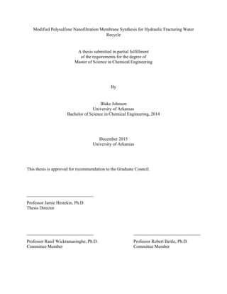
Filtration of commercial membranes was conducted by Haley Cleous and Long Tran to
determine the ion rejection of calcium and sodium in nanofiltration.77,78
Five commercial
membranes produced by Sepro were tested at operating pressures ranging from 250-800 psi in
solutions containing 50,000 mg/L of sodium and 16,000 mg/L of calcium. The results of the
mixture of sodium chloride and calcium chloride are shown in Figure 8 and Figure 9. These
concentrations match the measured calcium chloride and sodium chloride found in Texas
flowback.
In ideal solutions containing only calcium chloride at measured concentrations, NF3A and
NF3.1A outperformed the other commercial membranes. At pressures above 600 psig, NF3A
0.0
10.0
20.0
30.0
40.0
50.0
60.0
70.0
80.0
250 400 600 700 800
Rejection%
Pressure (psi)
Rejection of Calcium for NF Membranes
NF3A NF3.1A NF2A NF6 XN45
Figure 8: Rejection of calcium in filtration using commercial nanofiltration membranes.78
This graph was produced by Long Tran.
40. 35
rejected between 84% and 91% of calcium in the solution, and NF3.1A rejected between 94%
and 95.5%. Of these two membranes, NF3A had far superior performance in real world
solutions. NF3A showed the highest rejection of calcium: 69.8% at both 700 and 800 psig. This
membrane also resulted in the lowest rejection of sodium at 4% at 600, 700, and 800 psig.
NF3.1A only rejected 53.6% and 49.7% of calcium at 700 and 800 psig respectively, and
rejected as much as 25% sodium at 700 psig, resulting in a far lower separation than NF3A.
As previously stated, the 69.8% rejection of calcium was inadequate to reduce the calcium
concentration required for flowback reuse. To reduce the concentration to below 2,000 mg/L,
new membranes were required that had a greater rejection of calcium.
Due to the instability of the quaternary ammonia polysulfone membranes in water, filtration
testing could not be conducted with the custom membranes created in this experiment. In
0.0
5.0
10.0
15.0
20.0
25.0
30.0
35.0
250 400 600 700 800
Rejection%
Pressure (psi)
Rejection of Sodium for NF Membranes
NF3A NF3.1A NF2A NF6 XN45
Figure 9: Rejection of sodium in filtration using commercial nanofiltration membranes.78
This graph was produced by Long Tran.
41. 36
addition, limitations with the phase inversion apparatus meant that membranes of an adequate
size could not be produced to conduct filtration testing with the reverse osmosis apparatus
present in the lab. Modifications were made to a dead-end flow unit to allow for tangential flow
filtration. Filtration testing would have been conducted using the modified Millipore Filtration
Unit shown in Appendix 8.2.
4.3. Characterization:
4.3.1. Evapoporometry
For pore diameter characterization, a technique known as evapoporometry was used to correlate
the evaporation of isopropanol from membrane pores to the pore diameter. Extensive tests were
run to determine the pore side distribution of polysulfone and commercial membranes, both in
this study and in research conducted by Haley Cleous. Unfortunately, the lack of refinements in
the procedure for performing evapoporometry resulted in potentially inaccurate, although
consistent, data. The initial procedure did not include soaking the membrane in isopropanol
before the experiment began. As a result, isopropanol began soaking into the membrane as the
evapoporometry was being conducted, and the standard evaporation rate was not consistent.
Additionally, the membrane was not fully saturated when the surface isopropanol evaporated,
and the pore diameters obtained instantaneous evaporation rates that were not representative of
the actual pore diameters. The issues created through the improper procedure are shown in
Figure 18 in Appendix 8.3. The procedure was altered so that membranes would be soaked for
several hours before evapoporometry was conducted. Short soaking times of 2-4 hours resulted
in curves that were improved but still incorrect, so a modification to an overnight soak was used,
and proper results were obtained using this soak time.
42. 37
Another issue that arose when obtaining evapoporometry results was a miscalculation in the
membrane thickness when conducting the phase inversion. Initial membranes were cast to a
thickness of 200 µm, as described in previous research.47
However, the thickness of the paper
backing was not taken into account, and the cast membranes only had a polymer thickness of 48
µm, with the backing making up 152 µm of the membrane thickness, producing plots like those
of Figure 17 in Appendix 8.3. These membranes had an average pore diameter of 57 nm—much
too low for nanofiltration. After these results were obtained, the casting thickness was increased
to include the thickness of the backing, which corrected the results showing large pore diameters.
Accounting for procedural changes in both evapoporometry and membrane casting, the new
membranes produced results more similar to that of commercial membranes, although with a
larger pore diameter and wider pores size distribution.
Testing of commercial membranes with Haley Cleous showed that the tested membranes had
large concentrations of pores below 2 nm, ranging from 41% to 69% of the pores.77
Of the
membranes, NF2A had the highest concentration of 2 nm or less pores at 68.9%, followed by
NF3A with 63.4%, shown in Figure 21 and Figure 22 respectively in Appendix 8.3. While NF2A
had the highest concentration of 2 nm and smaller pores, this membrane also had a considerable
concentration—roughly 9%—of 6 nm pores.
Table 5: Comparison between percent of pores below 2 nm and rejection of calcium and sodium
at 700 psig.
Membrane % of Pores below 2 nm Rejection of Na (700 psig) Rejection of Ca (700 psig)
NF2A 68.9% 29.2% 29.2%
NF3A 63.4% 4.0% 69.8%
NF3.1A 44.5% 21.1% 63.6%
NF6 41.1% 11.3% 7.10%
XN45 43.2% 16.2% 20.2%
43. 38
While NF2A had the highest concentration of small pores, it performed very poorly in filtration
testing, rejecting only 29.2% of calcium and the same percentage of sodium, neither of which are
desirable permeate concentrations for reuse. The best performing membrane, NF3A, had a
similar concentration of small pores, and a significantly improved selective rejection of sodium
and calcium. In opposition to NF2A, NF3A had a very small pore diameter distribution and
almost no notable concentrations of pores above 2.5 nm, shown in Figure Figure 23: Pore size
distribution of NF3.1A. in Appendix 8.3. NF3.1A, which has a much smaller concentration of 2
nm or smaller pores at 44.5%, had a rejection of sodium near that of NF2A but a rejection of
calcium just below NF3A. Similarly to the NF2A membrane, NF3.1A had a high concentration
of 6-8 nm pores; this range accounted for nearly 25% of the pores. Even consideration to the
undesirable pore characteristics of NF3.1A, this membrane had a greater selectivity and higher
calcium while having a larger pore diameter distribution and percentage of small pores than
NF2A. It could be correlated that a reduction in pore diameter distribution and average pore
diameter may not be the most efficient method to increase the selective rejection of calcium over
sodium. This led to the increased desire to explore positive charge as a means to further the
separation.
Early-cast membranes did not produce a desirable pore diameter distribution when compared to
that of commercial membranes. The standard polysulfone membranes measured an average pore
diameter of 16 nm, closer to that of an ultrafiltration membrane, which can be seen in Figure 19
of Appendix 8.3. The pore diameter is especially poor when compared to the commercial
membranes tested by Haley Cleous, which had a high percentage of 1 and 2 nm pores. It is
possible to improve this however by optimizing the casting process.
44. 39
After chloromethylation, amination, and crosslinking, new polysulfone membranes were tested
with evapoporometry using DI water, due to the isopropanol causing the membranes to swell.
These membranes produced a much more promising curve, shown in Figure 20 in Appendix 8.3.
The measured average pore diameter for these membranes was 6 nm, much closer to that of the
commercial membranes tested. This could have been a result of the slow phase inversion in the
salt water bath. Unfortunately, the pore diameter distribution was large in comparison to
commercial membranes, which had a very small concentration of large pores above 4 nm. Figure
24 in Appendix 8.3 shows that there is a moderate concentration of 1.5-3.5 nm pores, but there
are also higher concentrations of larger pore diameters ranging from 5-14 nm nearly equal to that
of small pores. This is likely an issue caused by the phase inversion process used in the
experiment; improved equipment to allow for consistent shearing and faster phase inversion
could produce higher quality membranes with a narrower pore diameter distribution.
While decreasing the pore diameter to lower values than those of commercial membranes would
potentially increase the separation, this is difficult due to the limitations of the apparatus being
used. Applying a secondary means of separation such as positive charge would have a stronger
effect in increasing the separation. The methods involved in producing positive charges in a
membrane are more feasible as well, due to the equipment and facilities made available by Dr.
McIntosh and Brian Walker in the chemistry department.
4.3.2. Titration
To determine the charge of commercial membranes, titration was performed by Haley Cleous to
quantify the positive or negative charge of the membranes.77
The titration tests showed that the
tested commercial membranes had a small charge density. These membranes each contained a
positive charge between 2.72 to 3.11 milli-equivalents (the number of functional groups) per
45. 40
square meter. While these equivalents are greater than those tested for other membranes, the
exact charge density could not be determined.52
The atomic absorption tests performed to
determine the presence of negative charges on the membranes were inconclusive, as the ion
concentrations obtained from the titration were too low to quantify using the standards available.
As such, a comparison between the equivalent positive and negative charges could not be made,
and the net charge could not be determined.
Regardless of how many negatively charged groups were present, a stronger equivalent positive
charge is likely required to produce the net positive charge desired for the selective separation.
Membranes tested with similar equivalents per square meter were predominantly negatively
charged or had a small net positive charge.52
Increasing the charge density will produce a
membrane with the desired separation characteristics.
4.3.3. Proton Nuclear Magnetic Resonance:
Due to the fact that the product was a modified version of polysulfone, analytical techniques
were required to quantify the polymer and determine the completion of the reaction. Proton
nuclear magnetic resonance (H-NMR) was used to characterize the unreacted polysulfone,
chloromethylated polysulfone, and quaternary ammonia polysulfone. Most literature for reacting
polysulfone to a functional polymer used this chloromethylation reaction, as the functional
polymer is highly reactive and produces distinct H-NMR plots.47,58,60
Chloromethylated
polysulfone can be easily formed into a membrane, and can be reacted with a strong nucleophile
to produce specific functional groups, namely a positively charge formed from a quaternary
ammonia functional group. The high concentration of positive charge formed from this polymer
could drastically increase the selective rejection of multivalent positively charged ions over
46. 41
Figure 10: NMR results of polysulfone polymer.
(a)
(b)
(a) (a)
(a) (a)
(b)
(b)
monovalent positively charged ions. This would allow for the collected flowback from hydraulic
fracturing operations to be reused in future hydraulic fracturing.
Samples for H-NMR characterization were taken by collecting polysulfone in chloroform
solution and quenching the sample in methanol to precipitate the polysulfone. The methanol and
chloroform were removed, and the sample was dried in a vacuum to remove the remaining
solvent. In some runs, not all solvent could be removed before H-NMR was run, resulting in
large peaks at 7.4 and 1.5. The solid polymer was mixed with deuterated chloroform (CDCl3) to
prevent interference.
Standard polysulfone produced H-NMR data as predicted by previous research, with the addition
of methanol and chloroform curves shown in Figure 10. The peak marked as (a) correspond to
47. 42
Figure 11: NMR results of chloromethylated polysulfone after procedure changes.
(a)
(b)
(c)
(a) (a)
(a) (a)
(b)
(b)
(c)
(c)
the four hydrogen atoms adjacent to the sulfone group, and peak (b) corresponds to the six
hydrogen atoms present in the two methyl groups. The integration of the peaks was performed by
correcting the value of the area at peak (a) to 4, allowing for the number of hydrogens present at
the characteristic peaks to be quantified.
Chloromethylated polysulfone was analyzed at different reaction times and batch sizes to
determine the optimum conditions for maximum substitution. H-NMR results revealed that the
chloromethylation of polysulfone was dependent on the polysulfone batch size and the reaction
time of the chloromethylation reactions. The half batch that initially provided successful results
was collected at 72 hours and immediately tested in H-NMR, showing a substitution of 26%. The
subsequent test was allowed to run for 96 hours and yielded a substitution of 69%, shown in
48. 43
Figure 11. When the batch size was increased to match the procedure used, a reaction time of
120 hours only produced a substitution of 58%. The final run that was conducted was allowed to
react for 240 hours, and H-NMR revealed a substitution of 88% shown in Figure 13 in Appendix
8.3. Comparisons of experimental results and literature substitutions under the same reactant
ratio and solvent concentration are listed in Table 6.
Table 6: Comparison of batch size, reaction temperature, and reaction time to degree of
substitution.
Batch Size (g of PS) Reaction Temp (C) Reaction Time (hours) Substitution
0.555,59,60,79
50 72 79%
558
55 48 50%
14.8862
60-70 72 75%
7.44 60 96 69%
14.88 60 120 58%
14.88 60 240 88%
H-NMR was also performed on quaternary ammonia polysulfone produced from the 69%
substituted chloromethylated polysulfone shown in Figure 14 in Appendix 8.3. The spectra
showed two peaks where the quaternary ammonia was thought to be, so the exact completion of
the reaction could not be determined. However, both peaks had integrated values close to that of
the expected substitution, so it was concluded that the amination was reacted to near completion.
4.3.4. Fourier Transform Infrared Spectroscopy:
Another analytical technique used to quantify the polysulfone was Fourier Transform Infrared
Spectroscopy (FTIR). However, the results obtained through FTIR were ultimately inconclusive.
While the characteristic peaks of modified polysulfone could be found in FTIR tests, neither the
characteristic peaks of the chloromethyl group nor the quaternary ammonia group had peaks with
the same magnitude described in any articles.47,58
In select FTIR results these peaks were
discernable and had a small magnitude (the peak present at 751 cm-1
in Figure 16 in Appendix
8.3). However, given the magnitude of H-NMR peaks of the same polymer batch, the FTIR peak
49. 44
magnitude did not indicate the degree of reaction actually present in the polymer. There were
also inconsistencies between FTIR peak magnitudes of the membranes, even between the same
polymer chains, and subsequent tests of different membrane pieces showed either different peak
magnitudes or complete shifts in the spectrum. These differences in peak magnitude could have
been the result of inconsistent or uneven spreading of reacted polymer in the membrane,
resulting in sections of membranes having higher concentrations of chloromethyl groups than
others. Spectrum shifts could have been the result of surface deformities resulting in more open
space being analyzed. This led to a high degree of variability between tests and difficulty in
comparing results between different polymer batches, examples of which are shown in Figure 15
and Figure 16 in Appendix 8.3. As a result, FTIR was not used in the determination of the
polymer functional groups.
4.3.5. Scanning Electron Microscopy:
To determine the surface characteristics of the membranes produced, scanning electron
microscopy (SEM) was required to observe the characteristics, irregularities and defects of the
membranes. SEM analysis of unmodified polysulfone membranes revealed a flat surface where
several types of irregularities could be seen, including protrusions, creases (shown in Figure 12),
and foreign grain structures. Due to the limited resolution of SEM images, pore diameter analysis
couldn’t be performed using this technique, as the pores were determined to be in the nanometer
scale through evapoporometry. Pores could be seen, however, as numerous black spots that
covered the surface.
No SEM analyses were performed on the quaternary ammonia polysulfone membranes, due to
the difficulty of producing stable membranes. Membranes were required to be dehydrated before
scanning, and the quaternary ammonia polysulfone membranes had to remain wetted with salt
50. 45
Figure 12: SEM surface image of an unmodified polysulfone membrane.
water, otherwise they would deform. As a result, membranes prepared for SEM analysis became
deformed and unusable for analysis when testing was attempted, and SEM could not be
performed on stable membranes due to the fact that they were not fully dried. Environemntal
SEM—a related SEM technique—could have been used on these membranes, but the decreased
contrast would have decrased the quality of the images to the point that pores could not be
resolved.
51. 46
5. Conclusions:
The method of producing chloromethylated polysulfone was tested and optimized. Experiments
using methods of several previous research projects produced unreacted and potentially
crosslinked polymers.47,58
A low concentration of polysulfone—less than 2% of polysulfone in
chloroform solvent—and a high ratio of reactants to polymer—10:1—are required to
successfully produce chloromethylated polysulfone.55,62
The required reaction times were also
significantly longer than those mentioned in previous research, which ranged from 5 to 120
hours. Batches reacted for 120 hours only produced one functional group on each monomer, and
240 hours was required to approach two functional groups per monomer.
Amination with trimethylamine was successful, but did not produce desired qualities in
membranes. The solubility of quaternary ammonia polysulfone in water caused severe swelling
with surface modification, and inhibited phase inversion with bulk modification. Phase-inverted
membranes were still soluble in water, most organic compounds, and low molarity salt solutions.
It is possible that the presence of high concenrations of functional groups prevented proper
crosslinking, and other aminating procedures should be pursued.
Crosslinking with glutaraldehyde was only successful with specific polymer batches, and only
improved the solubility in water. Polymer batches substituted to 58% were successfully
crosslinked, but were still soluble in organic compounds and quickly deformed when left in open
air. At higher degrees of substitution, the polymer was not successfully crosslinked at the
concentrations used, and the membrane swelled in the glutaraldehyde solution. Either a higher
concentration of glutaraldehyde should be used or a lower degree of substitution of
chloromethylated polysulfone should be used for amination and subsequent crosslinking.
52. 47
The membranes produced were of much lower quality than commercial membranes, with many
of them having defects, including rippling on the polymer, non-uniform thickness from one side
of the membrane to another, and large holes where air bubbles formed could have prevented
polymer coating. Polysulfone membranes had a considerably wider pore diameter distribution
than commercial nanofiltration membranes, and quaternary ammonia membranes had nearly
triple the average pore diameter, although this could potentially be negligible effect on
separations when the separation effect of surface charge is accounted for.
Due to the large quantities of hazardous chemicals used in the chloromethylation reaction, as
well as the reaction times required for adequate substitution, the chloromethylation of
polysulfone does not seem to be a safe process for industrial applications. The standard operating
procedure used a maximum chloroform volume of 750 mL to produce a batch of polysulfone
with a final mass of roughly 18 g. Scaling up this process from the initial 100 mL batch size led
to a use of 42.5 mL of trimethylchlorosilane and 0.39 g of stannic chloride to complete the
reaction. The hazardous nature of trimethylchlorosilane makes storing large quantities of the
material unsafe, as both the liquid and vapor phases are highly flammable and can cause skin
corrosion and eye damage. The use of large quantities of chloroform—a known carcinogen—is
also troubling, as large quantities are needed to make a small batch of polymer, and the output of
product cannot be increased without sacrificing the quality of the polysulfone. To produce
industrial quantities of chloromethylated polysulfone, several liters of chloroform may be
required to make a few hundred grams of polymer. Additionally, the long reaction time required
creates an unsafe environment, as these compounds must be mixed near the boiling point of
chloroform for periods over ten days for a complete reaction, and periods near a week for a 50%
degree of substitution.
53. 48
6. Future Work:
In light of the quaternary ammonia polysulfone membranes being unstable in water, a new
aminating agent is necessary if a water insoluble membrane is to be produced. Amines related to
trimethylamine should be explored with caution. Ethylamine, dimethylamine, and methylamine
are classified as highly hazardous by OSHA, and as such will require a meticulous standard
operating procedure (SOP) like that for trimethylchlorosilane in Appendix 8.1. If these are used,
then new equipment will be required and—as per OSHA regulations—undergraduates will not
be allowed to work with the procedure.
Both diethylamine and triethylamine are potential aminating agents that could be explored.
Diethylamine is less flammable than trimethylamine, although the compound has a higher health
and reactivity risk. Triethylamine was suggested by the chemistry department as a safer
alternative to trimethylamine. However, it was noted that steric hindrance will severely increase
the required time for the SN2 reaction due to the longer ethyl chains. This will both slow down
research and create an additional safety hazard by having a hazardous chemical in the fume hood
for long periods of time, well exceeding 24 hours.
Recommendations from faculty in the chemistry department and used in several articles are
pyridine compounds.55
Pyridine is a heterocyclic organic molecule with a similar structure to
benzene with one methine group replaced with nitrogen. Of particular interest is 4,4’-bipyridine.
This compound is composed of two pyridine molecules bound together at the fourth methine on
each chain, leaving the nitrogen atoms at opposing ends of the compound. This compound is
particularly promising due to the ability to crosslink without the use of secondary compounds
such as glutaraldehyde.80
Additionally, aminated polysulfone that is crosslinked with 4,4’-
bipyridine contains two positive charges, one on each tertiary amine, increasing charge density.
54. 49
These two effects could lead to a more stable membrane with a greater rejection of positively
charged ions.
Alternatively, 4-phenylpyridine has been recommended. The structure of this pyridine is
identical to that of 4,4’-bipyridine, but with only one nitrogen group.
Optimization of the chloromethylation reaction should be investigated as well. Limited reactions
were run to focus efforts on optimizing the amination of the chloromethylated polysulfone.
Additional tests should be run to plot the substitution of the chloromethyl functional group over
time. This can be performed by taking a sample of the reaction solution every 12 to 24 hours and
analyzing it through H-NMR. Plotting this data with several repetitions would allow for the
creation a model for predicting the time required to reach a desired substitution.
To determine if the behavior of quaternary ammonia polysulfone is determined by the
substitution of amine groups to the polysulfone chain, additional tests should be run to aminate
low degree of substitution polymer—less than 50% chloromethylated polysulfone. It is possible
that the high grouping of positively charged amine groups or electrostatic interactions with the
methyl groups caused the quaternary ammonia polysulfone to become unstable in water. A
reduced concentration of these groups could result in a more stable membrane. If stable
membranes can be produced this way, filtration testing should be conducted with different
degrees of substitution to determine the required charge density to perform the calcium filtration.
55. 50
7. References:
1. Struchtemeyer CG, Elshahed MS. Bacterial communities associated with hydraulic fracturing
fluids in thermogenic natural gas wells in north central texas, USA. FEMS Microbiol Ecol.
2012;81(1):13-25.
2. Miller DJ, Huang X, Li H, et al. Fouling-resistant membranes for the treatment of flowback
water from hydraulic shale fracturing: A pilot study. J Membr Sci. 2013;437:265-275.
3. Gregory KB, Vidic RD, Dzombak DA. Water management challenges associated with the
production of shale gas by hydraulic fracturing. Elements. 2011;7(3):181-186.
4. Kargbo DM, Wilhelm RG, Campbell DJ. Natural gas plays in the marcellus shale: Challenges
and potential opportunities. Environ Sci Technol. 2010;44(15):5679-5684.
5. Hammer R, VanBriesen J, Levine L. In fracking’s wake: New rules are needed to protect our
health and environment from contaminated wastewater. Natural Resources Defense
Council. 2012;11.
6. Haluszczak LO, Rose AW, Kump LR. Geochemical evaluation of flowback brine from
marcellus gas wells in pennsylvania, USA. Appl Geochem. 2013;28:55-61.
7. Schmidt CW. Estimating wastewater impacts from fracking. Environ Health Perspect.
2013;121(4):A117-a117.
8. Miller P. Future of hydraulic fracturing depends on effective water treatment. Hydrocarbon
Process. 2011;90(7):13-13.
9. Cooley H, Donnelly K, Ross N, Luu P. Hydraulic fracturing and water resources: Separating
the frack from the fiction. Oakland, California: Pacific Institute. 2012.
10. Moore JR, Glaser SD. Self‐potential observations during hydraulic fracturing. Journal of
Geophysical Research: Solid Earth (1978–2012). 2007;112(B2).
11. Barbot E, Vidic NS, Gregory KB, Vidic RD. Spatial and temporal correlation of water
quality parameters of produced waters from devonian-age shale following hydraulic
fracturing. Environ Sci Technol. 2013;47(6):2562-2569.
12. Shelukhin V, Baikov V, Golovin S, Davletbaev A, Starovoitov V. Fractured water injection
wells: Pressure transient analysis. Int J Solids Structures. 2014;51(11):2116-2122.
13. Vengosh A, Jackson RB, Warner N, Darrah TH, Kondash A. A critical review of the risks to
water resources from unconventional shale gas development and hydraulic fracturing in the
united states. Environ Sci Technol. 2014;48(15):8334-8348.
56. 51
14. Rahm BG, Riha SJ. Evolving shale gas management: Water resource risks, impacts, and
lessons learned. Environmental Science: Processes & Impacts. 2014;16(6):1400-1412.
15. Lutz BD, Lewis AN, Doyle MW. Generation, transport, and disposal of wastewater
associated with marcellus shale gas development. Water Resour Res. 2013;49(2):647-656.
16. Wiseman HJ. Untested waters: The rise of hydraulic fracturing in oil and gas production and
the need to revisit regulation. Fordham Environmental Law Review. 2009;20:115.
17. Rahm D. Regulating hydraulic fracturing in shale gas plays: The case of texas. Energy
Policy. 2011;39(5):2974-2981.
18. Rahm BG, Bates JT, Bertoia LR, Galford AE, Yoxtheimer DA, Riha SJ. Wastewater
management and marcellus shale gas development: Trends, drivers, and planning
implications. J Environ Manage. 2013;120(0):105-113.
19. Murali Mohan A, Hartsock A, Hammack RW, Vidic RD, Gregory KB. Microbial
communities in flowback water impoundments from hydraulic fracturing for recovery of
shale gas. FEMS Microbiol Ecol. 2013;86(3):567-580.
20. Pombo F, Magrini A, Szklo A. Technology roadmap for wastewater reuse in petroleum
refineries in brazil. INTECH Open Access Publisher; 2011.
21. Michel MM, Reczek L, Granops M, Rudnicki P, Piech A. Pretreatment and desalination of
flowback water from the hydraulic fracturing. Desalination and Water Treatment.
2015(ahead-of-print):1-10.
22. Olsson O, Weichgrebe D, Rosenwinkel K. Hydraulic fracturing wastewater in germany:
Composition, treatment, concerns. Environmental earth sciences. 2013;70(8):3895-3906.
23. Mulder M. Basic principles of membrane technology. In: Springer Science & Business
Media; 1996:56-58, 299-303.
24. Petersen RJ. Composite reverse osmosis and nanofiltration membranes. J Membr Sci.
1993;83(1):81-150.
25. Bennett A. Desalination and water reuse: What's the future for forward osmosis? Filtration +
Separation. 2013;50(5):28-34.
26. Greenlee LF, Lawler DF, Freeman BD, Marrot B, Moulin P. Reverse osmosis desalination:
Water sources, technology, and today's challenges. Water Res. 2009;43(9):2317-2348.
27. Fritzmann C, Löwenberg J, Wintgens T, Melin T. State-of-the-art of reverse osmosis
desalination. Desalination. 2007;216(1):1-76.
57. 52
28. Bartels C, Wilf M, Andes K, Iong J. Design considerations for wastewater treatment by
reverse osmosis. Water Science & Technology. 2005;51(6-7):473-482.
29. Kasemset S, Lee A, Miller DJ, Freeman BD, Sharma MM. Effect of polydopamine
deposition conditions on fouling resistance, physical properties, and permeation properties
of reverse osmosis membranes in oil/water separation. J Membr Sci. 2013;425–426(0):208-
216.
30. Ely JW, Fraim M, Horn AD, Jakhete SD. Game changing technology for treating and
recycling frac water. . 2011.
31. McGovern RK, Lienhard V JH. On the potential of forward osmosis to energetically
outperform reverse osmosis desalination. J Membr Sci. 2014;469(0):245-250.
32. Valladares Linares R, Li Z, Sarp S, Bucs SS, Amy G, Vrouwenvelder JS. Forward osmosis
niches in seawater desalination and wastewater reuse. Water Res. 2014;66(0):122-139.
33. Coday BD, Xu P, Beaudry EG, et al. The sweet spot of forward osmosis: Treatment of
produced water, drilling wastewater, and other complex and difficult liquid streams.
Desalination. 2014;333(1):23-35.
34. Yun T, Koo J, Sohn J, Lee S. Pressure assisted forward osmosis for shale gas wastewater
treatment. Desalination and Water Treatment. 2015;54(4-5):829-837.
35. Field RW, Wu JJ. Mass transfer limitations in forward osmosis: Are some potential
applications overhyped? Desalination. 2013;318(0):118-124.
36. McCutcheon JR, McGinnis RL, Elimelech M. A novel ammonia—carbon dioxide forward
(direct) osmosis desalination process. Desalination. 2005;174(1):1-11.
37. Coday BD, Cath TY. Forward osmosis: Novel desalination of produced water and fracturing
flowback. Journal-American Water Works Association. 2014;106(2):E55-E66.
38. Hickenbottom KL, Hancock NT, Hutchings NR, et al. Forward osmosis treatment of drilling
mud and fracturing wastewater from oil and gas operations. Desalination. 2013;312(0):60-
66.
39. Li X, Zhao B, Wang Z, et al. Water reclamation from shale gas drilling flow-back fluid using
a novel forward osmosis–vacuum membrane distillation hybrid system. Water Science &
Technology. 2014;69(5):1036-1044.
40. Zhang S, Wang P, Fu X, Chung T. Sustainable water recovery from oily wastewater via
forward osmosis-membrane distillation (FO-MD). Water Res. 2014;52(0):112-121.
58. 53
41. McGinnis RL, Hancock NT, Nowosielski-Slepowron MS, McGurgan GD. Pilot
demonstration of the NH3/CO2 forward osmosis desalination process on high salinity
brines. Desalination. 2013;312(0):67-74.
42. McGovern RK, Mizerak JP, Zubair SM, Lienhard V JH. Three dimensionless parameters
influencing the optimal membrane orientation for forward osmosis. J Membr Sci.
2014;458(0):104-110.
43. Glazer YR, Kjellsson JB, Sanders KT, Webber ME. Potential for using energy from flared
gas for on-site hydraulic fracturing wastewater treatment in texas. Environmental Science &
Technology Letters. 2014;1(7):300-304.
44. Eriksson P. Nanofiltration extends the range of membrane filtration. Environ Prog.
1988;7(1):58-62.
45. Bowen WR, Mohammad AW, Hilal N. Characterisation of nanofiltration membranes for
predictive purposes — use of salts, uncharged solutes and atomic force microscopy. J
Membr Sci. 1997;126(1):91-105.
46. Teixeira MR, Rosa MJ, Nyström M. The role of membrane charge on nanofiltration
performance. J Membr Sci. 2005;265(1–2):160-166.
47. Rajagopalan M, Bhattacharya PK. Preparation and characterization of positively charged
polysulfone nanofiltration membranes. Journal of Polymer Engineering. 2013;33:369.
48. Deng H, Xu Y, Chen Q, Wei X, Zhu B. High flux positively charged nanofiltration
membranes prepared by UV-initiated graft polymerization of methacrylatoethyl trimethyl
ammonium chloride (DMC) onto polysulfone membranes. J Membr Sci. 2011;366(1):363-
372.
49. Bowen WR, Mukhtar H. Characterisation and prediction of separation performance of
nanofiltration membranes. J Membr Sci. 1996;112(2):263-274.
50. Childress AE, Elimelech M. Relating nanofiltration membrane performance to membrane
charge (electrokinetic) characteristics. Environ Sci Technol. 2000;34(17):3710-3716.
51. Schaep J, Van der Bruggen B, Vandecasteele C, Wilms D. Influence of ion size and charge in
nanofiltration. Separation and Purification Technology. 1998;14(1–3):155-162.
52. Schaep J, Vandecasteele C. Evaluating the charge of nanofiltration membranes. J Membr Sci.
2001;188(1):129-136.
53. Yu J, Rutledge G. Encyclopedia of polymer science and technology. . 2007.
59. 54
54. Warshawsky A, Kahana N, Deshe A, Gottlieb HE, Arad-Yellin R. Halomethylated
polysulfone: Reactive intermediates to neutral and ionic film-forming polymers. Journal of
Polymer Science Part A: Polymer Chemistry. 1990;28(11):2885-2905.
55. Avram E, Butuc E, Luca C, Druta I. Polymers with pendant functional group. III.
polysulfones containing viologen group. Journal of Macromolecular Science, Part A.
1997;34(9):1701-1714.
56. Noshay A, Robeson L. Sulfonated polysulfone. J Appl Polym Sci. 1976;20(7):1885-1903.
57. Ioan S, Filimon A, Avram E. Influence of the degree of substitution on the solution
properties of chloromethylated polysulfone. J Appl Polym Sci. 2006;101(1):524-531.
58. Pantamas N, Khonkeng C, Krachodnok S, Chaisena A. Ecofriendly and simplified synthetic
route for polysulfone-based solid-state alkaline electrolyte membrane. American Journal of
Applied Sciences. 2012;9(10):1577.
59. Avram E, Brebu MA, Warshawsky A, Vasile C. Polymers with pendent functional groups.
V. thermooxidative and thermal behavior of chloromethylated polysulfones. Polym Degrad
Stab. 2000;69(2):175-181.
60. Avram E. Polymers with pendent functional groups. VI. A comparative study on the
chloromethylation of linear polystyrene and polysulfone with paraformaldehyde/Me3SiCl.
Polym Plast Technol Eng. 2001;40(3):275-281.
61. Park JY, Acar MH, Akthakul A, Kuhlman W, Mayes AM. Polysulfone-graft-poly(ethylene
glycol) graft copolymers for surface modification of polysulfone membranes. Biomaterials.
2006;27(6):856-865.
62. Dong H, Xu Y, Yi Z, Shi J. Modification of polysulfone membranes via surface-initiated
atom transfer radical polymerization. Appl Surf Sci. 2009;255(21):8860-8866.
63. Kimmerle K, Strathmann H. Analysis of the structure-determining process of phase inversion
membranes. Desalination. 1990;79(2):283-302.
64. Pan J, Li Y, Zhuang L, Lu J. Self-crosslinked alkaline polymer electrolyte exceptionally
stable at 90 C. Chemical Communications. 2010;46(45):8597-8599.
65. Zhao Y, Pan J, Yu H, et al. Quaternary ammonia polysulfone-PTFE composite alkaline anion
exchange membrane for fuel cells application. Int J Hydrogen Energy. 2013;38(4):1983-
1987.
66. Pan J, Lu S, Li Y, Huang A, Zhuang L, Lu J. High‐Performance alkaline polymer electrolyte
for fuel cell applications. Advanced Functional Materials. 2010;20(2):312-319.
60. 55
67. Wienk IM, Boom RM, Beerlage MAM, Bulte AMW, Smolders CA, Strathmann H. Recent
advances in the formation of phase inversion membranes made from amorphous or semi-
crystalline polymers. J Membr Sci. 1996;113(2):361-371.
68. Hansen CM. Hansen solubility parameters: A user's handbook. CRC press; 2007.
69. Gharagheizi F. New procedure to calculate the hansen solubility parameters of polymers. J
Appl Polym Sci. 2007;103(1):31-36.
70. Barton A. Applications of solubility parameters and other cohesion parameters in polymer
science and technology. Pure and Applied Chemistry. 1985;57(7):905-912.
71. Hestekin J, Lin Y, Frank J, Snyder S, St. Martin E. Electrochemical enhancement of glucose
oxidase kinetics: Gluconic acid production with anion exchange membrane reactor. J Appl
Electrochem. 2002;32(9):1049-1052.
72. Krantz WB, Greenberg AR, Kujundzic E, Yeo A, Hosseini SS. Evapoporometry: A novel
technique for determining the pore-size distribution of membranes. J Membr Sci.
2013;438(0):153-166.
73. Merriman L, Moix A, Beitle R, Hestekin J. Carbon dioxide gas delivery to thin-film aqueous
systems via hollow fiber membranes. Chem Eng J. 2014;253(0):165-173.
74. Fisher LR, Israelachvili JN. Experimental studies on the applicability of the kelvin equation
to highly curved concave menisci. J Colloid Interface Sci. 1981;80(2):528-541.
75. Takei T, Chikazawa M, Kanazawa T. Validity of the kelvin equation in estimation of small
pore size by nitrogen adsorption. Colloid Polym Sci. 1997;275(12):1156-1161.
76. Al-Sahali M, Al-Qattan S. Performance analysis of small capacity reverse osmosis
desalination plants. Kuwait J Sci Eng. 2012;39(2 B):231-253.
77. Cleous H. Recycling produced water for hydraulic fracturing using nanofiltration
membranes. University of Arkansas; 2014.
78. Tran L. Hydraulic fracturing water recycle through optimal ultrafiltration and nanofiltration
membranes system design. University of Arkansas; 2014.
79. Cozan V, Butuc E, Avram E, Airinei A. Pendant functional group copolyether sulfones: III.
modified copolyether sulfones with bisphenolic copper chelate. Applied organometallic
chemistry. 2003;17(5):282-286.
80. Sata T. Anion exchange membrane with viologen moiety as anion exchange groups and
generation of photo-induced electrical potential from the membrane. J Membr Sci.
1996;118(1):121-126.