The document discusses potential design improvements for motion picture film projectors. It describes a new design for the intermittent mechanism called the Quickermittent, which uses a star wheel with curved slot profiles. This allows the indexing time to be reduced while maintaining control over acceleration and load forces. A reduced indexing time increases the amount of screen light during each frame. The document also discusses opportunities to improve the lamp house design to increase light efficiency and uniformity, providing benefits such as higher screen luminance.
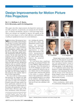
2. intermittently rotating star wheel, are
widely used in motion picture film pro-
jectors to advance the film through a
film gate having a projection aperture
(Fig. 1). The film is moved, frame by
frame, by the mechanism until an
image frame is in alignment with the
aperture. It is then held stationary for a
discrete period during which light is
passed through the aperture, film
frame, projection lens, and onto a
screen. The star wheel shares its central
shaft with a sprocket, the teeth of which
engage perforations in the film. When
the driver moves the star wheel, both
the star wheel and the film experience a
resulting intermittent motion.
Motion picture film is typically pro-
jected at a rate of 24 frames/sec, so a
new film frame is positioned in the pro-
jection aperture every 1/24 sec, or ~42
ms. The standard Geneva mechanism
moves a film frame into the projection
aperture with an indexing time of ~1/4
of the frame period, or ~10.5 ms. As
shown in Fig. 2(a), the star accelerates
slowly at first, increases rapidly to a
peak acceleration, then suddenly
reverses to peak deceleration, after
which acceleration gradually tapers off.
As a result, the star, sprocket, and film
move slowly with minimal displace-
ment for the first ~15o of driver rota-
tion, and thus only gradually reach
peak velocity before slowing down dur-
ing the deceleration phase.
The timing relationships of the star
movement and shutter operation are
shown in Figs. 2(b) and 2(c). During
essentially all of this indexing time, the
shutter blocks the light incident to the
film and prevents the appearance of
“travel ghost.” The projectable frame
time, which would appear to be 3/4 of
the total frame period, is further
reduced to only 1/2 of the total, as the
typical projector employs a two-bladed
shutter to provide two blanking periods
per frame, thus boosting the apparent
frame rate to 48 frames/sec, thereby
reducing the flicker perceived by the
human eye. Furthermore, it is necessary
for these two shutter intervals to be
nominally equal in duration in order to
limit perceived flicker. Therefore,
because one blanking period must be
1/4 of the frame time
in order to blank the
projected image as
the film moves, the
other blanking period
must be of essentially
the same duration.
The star wheel is
the key element in
enabling the Geneva
mechanism to con-
vert uniform rotary
motion to incremen-
tal rotary motion.
Traditionally, the
wheel has four equal-
ly spaced straight
slots radially extend-
ing around the
periphery of the star.
Interposed between
these slots are con-
cave cam guide sur-
faces, which, like the
slots, are uniformly
dimensioned and
arranged. A driver,
comprising a restraining cam, a drive
arm, and a drive pin near the far end of
the arm, is employed for indexing the
star wheel. The restraining cam has a
convex side cam surface, configured to
engage the concave cam guide surfaces
of the star wheel.
The close contact of the convex cam
surface to the concave cam guide sur-
faces restrains the star wheel from
experiencing rotary motion except dur-
ing the periods in which it is driven by
the drive pin. The star wheel is thus
restrained intermittently, and in such a
manner that the straight slots receive
the drive pin sequentially. Thus, in the
conventional projector intermittent,
each 360o revolution of the driver pro-
duces 90o of rotation of the star wheel
and attached sprocket. Correspond-
ingly, a standard two-bladed shutter
utilizes a pair of opposing blades, each
providing beam blockage over 90o of
its own rotation.
If the indexing time of the Geneva
mechanism could be reduced, the shut-
ter blanking periods could, in turn, be
shortened, thereby increasing available
screen light visible within a frame. Put
simply, the indexing time might be
reduced by using a star wheel with only
three straight slots, in which case,
engagement of the star wheel with the
driver pin occurs over only 60o of the
360o revolution of the driver, provid-
ing an indexing time of ~7 ms per
frame to move a film frame into the
projecting aperture.
While a 3-slot star wheel would thus
decrease the indexing time (and thereby
increase the available projection time),
the acceleration forces applied to the
drive pin, slots, and load (the film and
film perforations) are greatly increased
over those of a 4-slot Geneva, making
the 3-slot mechanism undesirable for
use in a projector. While the drive pin
can be shaped3 to modify the accelera-
tion profile and reduce the forces on the
drive pin, a 3-slot Geneva mechanism
would still be prone to failure in a
motion picture projector application.
A variety of alternate designs for the
enhanced intermittent film drive mech-
anisms have been considered.4 The
778866 SMPTE Journal, November 2001 • wwwwww..ssmmppttee..oorrgg
DESIGN IMPROVEMENTS FOR MOTION PICTURE FILM PROJECTORS
Figure 2. Timing diagram for a standard Geneva mechanism.
3. most successful was the “Powers”
movement5 where the star wheel
employs four round pins, which
engage with a cam that has a single,
large diamond-shaped cam driver.
While this intermittent drive reduces
the indexing time to ~1/5 of a rotation
of the cam by supplying prolonged
periods of uniform controlled peak
acceleration to the star, a high sliding
velocity may introduce unsteadiness
and gradual pin wear. These effects
likely prevented the widespread adop-
tion of this mechanism.
A New Geneva Mechanism
A new Geneva mechanism for use in
motion picture film projection has been
developed6 and demonstrated. The star
wheel of the new design employs slots
with curved surface profiles, instead of
straight slots used in the traditional
mechanism. It has been demonstrated
that with the appropriate shaping of the
slot walls, the velocity profile encoun-
tered by the star wheel can be modified
to reduce the indexing time, while
maintaining control over the accelera-
tion and load forces experienced by the
film and the drive mechanism itself.
As shown in Fig. 3, the slot walls of
the star wheel have a concave portion
adjacent to the mouth of the slot, fol-
lowed by a slight convex portion in the
middle of the slot and a straight portion
innermost in the slot. The details of the
design of the slot shape can be adjusted
to control the slope of the ascent to
peak acceleration, the transition into
mid-index (the zero acceleration point),
and the acceleration profiles between
these two extremes. At operating
speeds, the drive pin
enters a slot and rides
along the concave,
convex, and straight
portions of the first
wall, then exits the
slot by riding along
the surfaces of the
opposing wall in
reverse order.
Unlike the conven-
tional Geneva mecha-
nism, the drive pin
does not snugly fit the
star wheel slots, except in the straight
innermost portion. As a result, the new
mechanism can experience some chat-
ter at very low speeds, as the drive pin
separates from the wall. However, at
normal operating speeds, with the iner-
tial torque many times greater than the
drag torque on the film, the drive pin
remains in contact with the appropriate
wall of the slot and the mechanism
functions without los-
ing control of the dri-
ven load.
To illustrate the
design concept more
fully, the timing dia-
gram in Fig. 4 shows
the relationship of the
acceleration and
velocity of the star
wheel to the pin load
and the shutter opera-
tion during the first
half of a frame time.
Basically, the curved
slots are shaped to
produce a prolonged
period of high accel-
eration prior to mid-
index and a similar
prolonged period of
deceleration after
mid-index, after which
the deceleration is
rapidly reduced to
zero.
Comparison of the
timing diagram for
the standard Geneva
mechanism (Fig. 2)
and the improved one
(Fig. 4), shows that the acceleration and
velocity motion profiles are shorter and
more abrupt at the beginning and end
of the index. While in the conventional
Geneva the drive pin is engaged with
the slot over 90o of rotation, the drive
pin of the new mechanism enters the
shaped slot later and leaves earlier,
effectively engaging over a lesser
angle. As the star wheel undergoes a
smooth and continuous motion through
mid-index, the pin load (Fig. 4d)
remains under control, thus minimizing
both the applied forces and the wear
experienced by both the mechanism
and the load (the film). As the design
concept specifies deliberate shaping of
the slot walls, which have a relatively
large surface area, wear on the mecha-
nism is minimized compared to alter-
nate approaches involving shaped or
high load drive pins.
Within limits, the new Geneva
mechanism, or Quickermittent, is
SMPTE Journal, November 2001 • wwwwww..ssmmppttee..oorrgg 778877
DESIGN IMPROVEMENTS FOR MOTION PICTURE FILM PROJECTORS
Figure 3. The new Geneva mechanism.
Figure 4. Timing diagram for the new Geneva mechanism.
4. amenable to a wide range of potential
designs utilizing different slot profiles
to provide different peak accelerations,
pin loads, and indexing times. A variety
of prototypes have been modeled and
tested, including a device that has near-
ly identical indexing time as that of the
conventional mechanism, but has
reduced peak acceleration and peak pin
loads (50% and 55%, respectively), for
reduced forces and wear on the mecha-
nism and on the film. Alternately, an
increased peak acceleration and peak
pin load can be traded off for reduced
indexing times, which is, of course, the
intended goal.
One such design utilized shaped slots
that provided a dramatically reduced
indexing time (64% or 6.7 ms) with
increased peak acceleration and pin
load (142% and 106%, respectively)
compared to the conventional Geneva.
Thus, this version of the Quickermittent
completes its indexing over only 56o of
rotation of the driving cam, compared
to 90o for the standard mechanism, and
provides 36% more screen light during
a frame time. A third, less aggresive
design, which has also been evaluated,
provided reduced indexing times (73%
or 7.7 ms or 66o rotation) and 27%
more screen light, with peak accelera-
tion and peak pin loads comparable to
the conventional Geneva (100.6% and
91%, respectively). As shown in the
timing diagram of Fig. 4(d), each of the
shutter blades will be closed for less
time than in the conventional projector,
and the perceived screen luminance
will be proportionally increased during
each frame. Of course, the actual light
gain achieved on-screen will be
reduced somewhat relative to the
design and tuning of the shutter to min-
imize travel ghost, which is the visual
perception of the moving film.
Thus far, Quickermittent Geneva
mechanisms have been successfully
prototyped and tested in Christie,
Simplex, and Century projectors, using
hardware appropriately adapted for
each system. Figure 5 illustrates the
Quickermittent star wheel, with its
curved slots, along with the standard
star wheel and cam. Designed to work
with the same cam driver, the new star
wheel is actually slightly smaller than
the standard one. In general, this new
intermittent can be retrofit into an exist-
ing projector, using the modified star
wheel and a conventional or slightly
modified cam driver, and with little or
no change to the reminder of the pro-
jection head. Gate tension may be
slightly higher in the modified pro-
jecter, in order to provide sufficient
film drag to maintain control over the
film and prevent film or mechanism
damage. Preliminary tests have indicat-
ed that the new mechanism tends to be
somewhat noisier than the conventional
mechanism, but the increased noise lev-
els are likely acceptable and can be
minimized with proper adjustment and
design.
The Projector Lamp House
The successful development of a
lamp house useful for motion picture
film projection appears to have been
one of the first optical design problems
of the industrial age. Many of the clas-
sical illumination optical designs, from
the Köhler system,7 to the fly’s eye illu-
minator,8 and the elliptical reflector
were either conceived, or enhanced, to
project film images. Generally, the con-
ventional lamp house used in motion
picture film projectors consists of a
short-arc xenon lamp set within a deep-
dish elliptical mirror. Compared to
numerous alternatives, many of which
involve combinations of reflectors and
lens elements, the basic lamp house,
with its single circularly symmetrical
elliptical reflector, is notable for its
simplicity and low cost. However, as
the typical lamp house overfills the rec-
tangular film aperture with a large
round beam of light, this system is
quite inefficient. Moreover, alignment
of these lamp houses, whether of the
xenon arc to the first focus of the
ellipse, or of the reflector and lamp to
the projection aperture and lens, has
proven sufficiently difficult and time
consuming that the effort overwhelms
many theaters. Although, over the
years, various opportunities have been
available for improvement in lamp
house design, many of the efforts to
date were directed to small adjustments
in the design of the elliptical reflectors
and coatings, or to debates over
whether to utilize horizontally or verti-
cally installed xenon arc lamps.
The Universal Lamp House
A new lamp house has been
designed and prototyped, with the
objective of improving the light effi-
ciency and uniformity of the light
delivery to the screen, as well as the
robustness and ease of alignment. In
particular, it was designed utilizing a
fly’s eye optical illumination system
working in combination with modern
xenon arc lamp modules.
The fly’s eye optical system, which
778888 SMPTE Journal, November 2001 • wwwwww..ssmmppttee..oorrgg
DESIGN IMPROVEMENTS FOR MOTION PICTURE FILM PROJECTORS
Figure 5. The standard star wheel (l), the driving cam (c), and the new star wheel (r).
5. uses lenslet arrays to reshape and
homogenize the light beam, was origi-
nally developed by Zeiss Ikon8 in the
1940s. This design approach, which
was later adapted to work in combina-
tion with the short-arc xenon lamp,9
was considered difficult to use because
of alignment issues with respect to its
“waffle” lens. In all likelihood, the
widespread adoption of a fly’s eye
design in cinematic projection was lim-
ited by the cost and difficulty of manu-
facturing the required lenslet arrays.
However, in recent decades, light
homogenizing illumination systems
employing either a fly’s eye design or
kaleidoscope optics have been exten-
sively developed for the photolithogra-
phy industry. More recently, such
designs have been successfully applied
in the design of electronic projection
systems, using xenon, metal halide, and
other arc sources. When such systems
are properly designed and implement-
ed, the optical alignment is actually less
sensitive to misalignment compared to
the equipment used in conventional
systems.
As shown in Fig. 6, the new lamp
house employs a series of condensing
lens elements and two lenslet arrays in
a classical fly’s eye optical system
between the lamp and the film gate.
The first condensing lens after the lamp
is used to fill the first lenslet array with
a specular beam. This array, construct-
ed of spherical lenses with rectangular
apertures, breaks the beam into a series
of beamlets that are coupled to the cor-
responding lenslets of the second array.
The second array, working in combi-
nation with a relay lens, images the
lenslets of the first array onto the film
gate in overlapping fashion, thus pro-
viding a rectangular area of uniform
illumination. A field lens located near
the film gate is used to image the sec-
ond array into the entrance pupil of the
projection lens. Compared to fly’s eye
designs in the past, this system benefits
from modern manufacturing methods
for producing lenslet arrays and also
utilizes modern light sources.
The prototype Universal lamp hous-
es are designed to accept either Cermax
EX-1500-F and EX-2400-F short-arc
xenon lamps, and MVDR 1.5-kW, 1.9-
kW, and 3.0-kW illumination modules.
Cermax lamps are integrated lamp
packages in which the electrodes, rare
gases, and arc are contained in an inte-
grated package with datum features.
Since these lamps operate with smaller
arc gaps compared to bulb lamps of the
same wattage, the arc plasma is smaller
and the light source is effectively
brighter (reduced etendue). By compar-
ison, the MVDR modules combine
conventional short-arc xenon bulb
lamps with compound reflectors, to
synthesize a brighter effective source
by capturing some light with the sec-
ondary reflector. This light is then recy-
cled back through the bulb and primary
reflector. These modular lamp sources
are relatively rugged and provide exter-
nal datum features for easy repeatable
installation. Within these modules, con-
ventional bulb xenon arc lamps are pre-
aligned to the compound reflectors
prior to installation in a projector.
Significantly brighter illumination,
compared to the conventional system,
is provided by combining brightness
enhanced xenon sources with a fly’s
eye system, which channels light
through a rectangular aperture. For
example, a prototype lamp house, con-
structed as described, demonstrated a
~35% light gain and 16 fL center
screen luminance through a scope aper-
ture when projected on a 30-ft screen
with a 114-ft throw while using a 1500-
W lamp.
The lamp house system seen in Fig.
6 also provides several secondary
advantages. In addition to the added
light efficiency, the screen illumination
has improved uniformity, with typically
only a 10 to 15% gradual roll-off from
center to corners. In practice, the effi-
ciency and uniformity improvements
delivered to the screen luminance by
the universal lamp house are dependent
on the choice of projection lens used
with a given system.
The process of light homogenization
also has the secondary advantage of
desensitizing the illumination to flicker
from arc and gas turbulence within the
lamp. Furthermore, the fly’s eye type of
design desensitizes the illumination to
horizontal or vertical misalignment of
the lamps, as shifts of ~1.0 mm will
cause minimal change in the illumina-
tion uniformity. These tolerances easily
fall within the repeatability of align-
ment provided by the datum features of
either the Cermax or the modular lamp
sources, thus providing simple, safe,
and repeatable lamp placement.
Additionally, the prototype system uses
an infrared filter, providing superior IR
rejection and a natural color tempera-
ture of 5500oK. Finally, the illumina-
tion system can be optionally config-
ured10 to suppress the visibility of
scratches and dust on the film with the
addition of a holographic or engineered
diffuser located in the gate upbeam of
the film.
A mechanically integrated version of
the lamp house with improved optics is
shown in Figs. 7 and 8. The optome-
chanics have been designed to provide
SMPTE Journal, November 2001 • wwwwww..ssmmppttee..oorrgg 778899
DESIGN IMPROVEMENTS FOR MOTION PICTURE FILM PROJECTORS
Figure 6. Optical layout with the Universal lamp house.
6. easy accurate alignment of the lens ele-
ments within the projector and easy
integration and alignment of the lamp
houses with the project heads. The ther-
mal design within the Universal lamp
house is engineered to both minimize
heat transfer among components and
modules and to quickly remove heat
from the various assemblies.
Theater Application
The Quickermittent and Universal
lamp house have been tested in combi-
nation and provided over 20 fL center
screen luminance on a CinemaScope
aperture 30-ft screen with a 1500-W
lamp, which is ~70% more light than
provided by a projector operating with
a standard intermittent and lamp house
equipped with a 2-kW lamp. Projection
with the “flat” or 1.85 projection aper-
tures shows a less dramatic ~40% light
gain, as light is lost from clipping by
the aperture plate.
Unlike many proposals for improv-
ing screen luminance by altering the
basic 35mm
film format,
these light gains
can be achieved
with minimally
d i s r u p t i v e
upgrades to
existing projec-
tion equipment.
The light effi-
ciency gains
provided by the
new intermit-
tent and lamp
house designs
could simply be
used to provide
a better screen
i m a g e .
Alternately, this
efficiency can
be used to light
an existing
screen with a
lower power
lamp than used
today. This
combination has
the additional
benefit of reducing the thermal load
through the film, thereby reducing film
buckle and the resulting shifts through
focus, and thus improving the image
quality. Likewise, the light efficiency
gain can also be traded away for a
reduction in scratch and dust visibility
in the projected image.10
Although both the Quickermittent
and the Universal lamp house have
been successfully demonstrated and
tested, these designs would benefit
from field testing and optimization
prior to widespread adoption by the
industry. Both designs lend themselves
to being retrofit into existing equipment
or current projector designs, with mini-
mal changes required to the equipment.
While Cermax lamps are simply more
costly, the additional expense intro-
duced by the modular lamp sources is
due mainly to the cost of the modules
themselves. However, these modules
can be re-lamped (usually by the manu-
facturer or a specialty vendor) and then
re-used by the theater. With the modu-
lar lamp sources, one lamp module can
be exchanged for another within min-
utes, without the need to re-align and
refocus the bulb within the projector.
Admittedly, the Universal lamp
house could be redesigned to accept
light from a conventional bulb lamp
and lamp house, however, the advan-
tages relative to performance, size, and
ease of use would be lessened. The ulti-
mate question relative to adoption of
the new lamp house, with its modern
xenon lamp sources, could be whether
the advantages relative to efficiency,
ease of use and alignment, and perfor-
mance outweigh the additional lamp
costs for the cash-strapped exhibition
industry.
Other Opportunities
There are other significant opportu-
nities to improve the projected image
quality provided by motion picture film
projectors. Compared to other effects
that degrade the projected image quali-
ty, such as scratches, dirt, and film
jump and weave, film buckle is the
least obvious, but perhaps most signifi-
cant contributor to quality loss.
Borberg11 describes both the basic phe-
nomenon of film buckle, as well as one
solution involving modulated air blasts
to mitigate the effect.
While much of the light incident on
the film is transmitted through it, and
subsequently imaged to the screen by
the projection lens, a portion of this
light is absorbed, either by the dyes in
the case of color film, or by the silver
grains in the case of black-and-white
film. The absorbed light heats the
film, which being an elastic material,
deforms out of plane. This thermally
induced deformation can shift the
image outside of the designed depth-
of-focus of the projection lens, there-
by degrading the on-screen image res-
olution.
The standard two-bladed shutter,
which is typically located between the
lamp source and the film gate, causes
the film to be pulse illuminated twice
per frame. The film buckles during the
first illumination period, relaxes some
during the intervening dark period, and
779900 SMPTE Journal, November 2001 • wwwwww..ssmmppttee..oorrgg
DESIGN IMPROVEMENTS FOR MOTION PICTURE FILM PROJECTORS
Figure 7. Mechanical design of the Universal lamp house.
Figure 8. Universal lamp house assembled.
7. then buckles (or deforms) further dur-
ing the second illumination period.
Film buckle can potentially be reduced
through either passive or active means,
by incorporating the appropriate design
changes to the projector. However,
these design changes, which need fur-
ther development, are more invasive to
the design of the projector head than
either the Quickermittent or the
Universal lamp house. If, however,
such changes were adopted and the film
buckle accordingly reduced, the pro-
jected image quality would be percep-
tually improved through the present
projection lenses provided by ISCO or
Schneider, or through any new and
improved projection lenses which
could be developed.
Acknowledgments
The authors would like to thank
Eastman Kodak Co. and the Enhancing
the Theatrical Experience (ETE) pro-
ject team for supporting these and other
development efforts directed towards
improving motion picture film projec-
tion. Additionally, Darryl Jones pro-
vided invaluable assistance and advice
in working with motion picture film
projection equipment, while Franklin
Ehrne provided considerable mechani-
cal engineering and design support.
Consideration is also due Gary
Nothhard, for his continuing support in
testing and characterizing the new lamp
house. Finally, thanks to Glenn
Berggren for providing many useful
insights relative to the performance lev-
els and developmental history of the
projection equipment used in the
motion picture industry.
References
1. Motion-Picture Projection and Theatre
Presentation Manual, Chap. 6, SMPTE:
New York, NY, 1969.
2. J. Kelly and G. Berggren, “Screen
Illumination of 35-mm Film Projection,”
SMPTE J., 92:1310-1313, Dec. 1983.
3. A. F. Victor, “Mechanical Movement,” U.S.
Patent no. 1,198,683, Sept. 1916.
4. A. Hayek, “Design Factors in 35mm
Intermittent Mechanisms,” J. SMPTE,
49:405-414, Nov. 1947.
5. N. Power, “Intermittent Driving Mechanism
for Motion Picture Machines,” U.S. Patent
no. 1,129,121, Feb. 23, 1915.
6. D. H. Kirkpatrick and A. F. Kurtz, “Geneva
Mechanism and Motion Picture Projector
Using Same,” U.S. Patent no. 6,183,087,
Feb. 6, 2001.
7. A. Köhler, “Lighting System for
Cinematographs,” U.S. Patent no. 1,143,287,
June 15, 1915.
8. K. Räntsch, “Illumination System,
Particularly for Projection Systems,” U.S.
Patent no. 2,326,970, Aug. 17, 1943.
9. H. Ulffers, “Xenon High-Pressure Lamps in
Motion Picture Theaters,” J. SMPTE,
67:389-391, June 1958.
10. A. F. Kurtz, “Image Transfer Illumination
System and Method,” U.S. Patent no.
5,754,278, May 19, 1998.
11. W. Borberg, “Modulating Air Blast for
Reducing Film Buckle,” J. SMPTE, 59:94-
100, Aug. 1952.
SMPTE Journal, November 2001 • wwwwww..ssmmppttee..oorrgg 779911
DESIGN IMPROVEMENTS FOR MOTION PICTURE FILM PROJECTORS
Christopher L. DuMont is a senior
technical associate in the
Entertainment Imaging business unit
of Eastman Kodak Co. He has a B.S.
from RIT in Imaging Science, and a
M.S. in analytical chemistry, also
from RIT. He has worked in motion
picture systems studies for the last 12
years, and in the military doing
remote sensing, prior to working at
Kodak. He has worked on develop-
ing new negative, intermediate,
hybrid and digital products for use in
the motion picture industry.
Dumont’s most recent projects were
developing the Kodak PreView
System and novel technologies for
use in the exhibition industry.
Dumont has been the author and
presenter of papers at numerous
SMPTE conferences. He holds six
U.S. patents in the imaging science
field for Kodak.
Andrew F. Kurtz is a senior
research scientist at Eastman Kodak
Co., where he has worked on the
development of optical technologies
and prototype systems for film scan-
ning, laser printing, and image pro-
jection. His work related to the
development of optical systems gen-
erally, and illumination systems and
optical devices in particular, has
resulted in 18 issued U.S. patents. He
is a recipient of a 1998 Prime Time
Emmy Award from the Academy of
Television Arts & Sciences for
Outstanding Achievement in
Engineering Development for his
work on the Spirit Datacine telecine
system.
Kurtz received both B.S. and M.S.
degrees in optics from the University
of Rochester. He is a member of the
SPIE, SMPTE, and SID.
Barry D. Silverstein is a senior
research scientist, Engineering
Physics Laboratory, Eastman Kodak
Co. He received a B.S. in optics from
the University of Rochester in 1984.
His career with Eastman Kodak has
been in the design and development
of optical read/write disk storage sys-
tems, space optics, laser printing sys-
tems, and image projection systems.
He has specialized in the design of
optical systems and in the packaging
of micro-optical components and
opto-electronic devices.
Silverstein has received two U.S.
patents related to optical systems
design.
David H. Kirkpatrick is a senior
development engineer at Eastman
Kodak Co. His responsibilities in the
Commercial and Government
Systems group include development
and processing of equipment for
large ground-based and orbiting mir-
ror systems, including the Chandra
X-Ray Observatory launched by
NASA in July 1999. Before joining
Kodak, he was involved in machine
tool design and development work at
Gleason Works. He has contributed
to three issued U.S. patents, general-
ly related to gear and drive mecha-
nisms.
Kirkpatrick received a BSME
degree from Lehigh University in
1972.
THE AUTHORS