
Recommended
Recommended
More Related Content
What's hot
What's hot (20)
Similar to Ilizarov Instrumentation 2-2.pdf
Similar to Ilizarov Instrumentation 2-2.pdf (20)
Recently uploaded
Recently uploaded (20)
Ilizarov Instrumentation 2-2.pdf
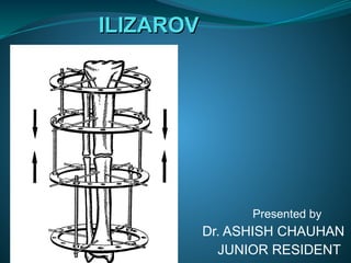
- 1. ILIZAROV ILIZAROV Presented by Dr. ASHISH CHAUHAN JUNIOR RESIDENT
- 2. HISTORY-Gavriil Abramovich Ilizarov(1921-1992) The MAN, The Creator, The Teacher MAGICIAN OF KURGAN Transosseous Osteosynthesis" (Springer Verlag, 1992, 800 pages) professor Ilizarov wrote: "Our research in medicine, biology and engineering has led to the evolution of more than 800 unique, highly effective methods of treatment Tension- Stress Effect" and formulated it thus: "slow, steady traction of tissues caused them to become metabolically activated, resulting in an increase in the proliferative and biosynthetic function
- 3. Instrumentation Primary components : Elements used to correct skeletal deformities. Eg. Ring wire, wire fixation bot and buckles, pin and pin clamps Secondary component : Element necessary for assembly of frame. Eg. Rods, plates, support, post, hinge, washer, sockets, bushing, bolts and nuts
- 4. Rings Principle component Made of stainless steel or carbon fiber to bear high stress ( up to 150 kg) Internal diameter measures from 80-240 mm. 80-140mm used in paediatric age group 150-240 mm used in adults
- 5. FUNCTIONS Support transfixation of ilizarov, olive wires and half pins Builds a fixator frame connecting two or more rings Props up frame’s supplementary parts.
- 6. HALF RINGS
- 7. FULL RINGS Advantages: Slightly lighter in weight Does not require nut and bolt to connect half rings It has 6 more holes to work or to connect hinges and small plates DISADVANTAGES: Post op if their is swelling full ring must be removed with diamond saw.
- 8. FIVE EIGHTH RING . ADVANTAGES: . less restricted joint as compared to full ring . More room for introduction of cross k wires as compared to half ring . For special care of soft tissue
- 9. HALF RING WITH CURVED ENDS . Used in deltoid region
- 10. Arches Larger diameter than half rings. Extra holes for use at the level of proximal femur or humerus Does not limit joint motion original ilizarov arches transfixed with k wires at the level of GT so there are chances of sciatic nerve injury
- 11. ITALIAN ARCHES Modification of original arches by dr cattagni Fixed with Schanz pins bicorticaly in prox. Femur Reduced risk of sciatic nerve injury Known as Italian arches
- 12. BOLTS
- 13. Bolts Hexagonal head of 10mm Threaded shaft of 6mm diameter. Pitch of thread is 1 mm Length of 10, 16 and 30 mm used. Have longitudinal holes or slot just below head to fix wires to the ring or other components of the frame It is uses to connect the threaded socket and bushing through the rings, for connecting plate, for fastening rods and half pins through socket aperture.
- 14. NUTS
- 15. Nuts Diameter-6 mm Height- 6,5 and 3 mm Pitch of thread-1mm So 1/4th turn four times per day is recommended distraction compression rate. Turn of nut is used as driving force in ilizarov system. .
- 16. FUNCTION OF NUTS Function: Tighten the connecting bolt Stabilized connecting rods Driving vector for distraction- compression movement Lock socket and bushing onto threaded rod Secure hinge clearance and gap on threaded rod Affix pulling wire of distraction device
- 17. Buckle Combine a plate with 2 fixed threaded rod with two hole plate held together with 2 nuts. A longitudinal groove hold a wire to ring like a slotted bolt. Allow mechanical derotation or angular correction
- 18. RODS 6 mm stainless steel threaded rods Come in 10 lengths 60- 400 mm Share the same pitch 1 mm Increase in length of rod decrease its bending potential thus at least 4 rods are used to connect 2 rings
- 19. Rods 6 mm thick stainless steel rod is main connector 4 rods at equidistant are used to connect 2 neighboring rings. By turning nuts we can fix rods to the frame We can produce desired compression or distraction needed Rods are machined so that thread causes 1 mm translational along its longitudinal axis with each complete 360˚ revolution of nut Slotted cannulated rod with 2x2 mm slot and length of 20 thread, act as pulling device.
- 20. Telescopic rod Hollow rods used as support and connecting elements of the rings. Base is machined to accept 10 mm open end wrench. Head have 2 holes : 1st for threaded rod 2nd for bolt to lock rods Provide stability when log distance spanning is required between rings Now hollow tube may contain slotted window with graduated metric marking on one side.
- 21. Plates Use to reinforce ring fixator Short plates are used as extension of rings Long plates used to reinforce large frames during bine fragment transport Plates with threaded rod used to support a hinge as well as a frame Twisted plates used to connect two components positioned at right angle to one another Curved plates used to increase circumference of half ring and connect two half ring
- 22. SHORT PLATE
- 23. LONG PLATE
- 24. MALE Support Type- male and female post Male post : threaded projection fixed with nut Female post- threaded hole fixed with bolt Function: Third wire can be connected to post Can also work as hinge Can be connected to other part of apparatus to provide additional stability Wire can be tensioned
- 25. FEMALE POST
- 26. Hinge post Have supporting base wit two flat surface matching the standard 10 mm wrench Important function is correction of angulation Type- male and female hinge post
- 27. WASHERS
- 28. Washer Washer is used to raise a wire fixation bolt to the wire that does not sit directly on ring Types : simple, slotted and conical Slotted washer : allow wire fixation on one side in special circumstances Conical washer : act as swivel for connecting rings or plates which are not parallel.
- 29. Tensioners Used to tension wire to an exact force, thus improvising stability for entire bone frame construct Types : dynamometric and standard wire tensioner Wire should be tensioned from 50-130 kg Amount of tensioning depends upon : Weight of patient Local bone quality Treatment plan Local frame construct Standard wire tensioner not calibrated and cumbersome to use.
- 30. Threaded socket & bushing Threaded rod interconnect threaded rods It stabilized two rings together Hole on side, can be used for threaded rod in horizontal direction
- 31. BUSHINGS Bushing is 12 mm long spacer with smooth longitudinal hole that provide free motion of threaded rod length wise.
- 32. Dynamometer Parts of dynamometer : Handle for applying pressure Dynamometer scale Fixed jaw Mobile jaw Using of dynamometer : Rotate handle anti clockwise until wire get inside Engage the fix jaw to the ring Rotate handle clockwise until desired tension is achieved Tighten the nut at desired tension Rotate handle anti clockwise to loosed the wire
- 33. Ring positioning Rings are main component Types : Main proximal frame supporting ring : It bears weight of entire construction. Located 3-5 cm away from joint Stabilizing frame supporting ring : may be stationary or moveable. Located 3-5 cm away from joint Pushing pulling ring : moveable ring used for compression or distraction. Located 3-5 cm distal to fracture-osteotomy- nonunion site Reference ring : used as reference for supporting rings or distraction-compression rings. It corresponds to apex of bone regulation Connecting rings : used for application of special forces in transverse or oblique direction for correcting deformities.
- 34. Assembly of circular fixator Major considerations : Stability of fixation of the frame to the bone The prevention of gross bone fragment motion Ability to manipulate bone and to perform necessary fragment movement such as straightening, bending, distraction, compression, rotation and combination of these movement Construction of frame can be done in advance or during surgery Important aspect of frame assembly: Ring positioning Ring inclination Ring orientation Ring level Spacing between skin and ring
- 35. Spacing between skin and ring At the narrowest gap space of at least 3 cm should be maintained between inner curve of ring and skin Achieved in 3 ways : Limb measured in 2 plane and largest diameter is considered. Add 6 cm to this diameter which provide you size of ring Attach most anticipated size and seek a space of 3 cm Use plastic template.
- 37. Loosely attached slotted fixation bolt at entrance site guide k-wire and prevent deflection during introduction and drilling One wire one hole to prevent incorrect positioning Push wire manually to bone before drilling
- 38. K WIRES ADVANTAGES OF K WIRES When drilled into the tissue destroy very little compact bone and marrow When tensioned properly it dampens vibration and prevent soft tissue and bony destruction because of elasticity After removal penetration holes are very small Small diameter holes less external contamination
- 39. Olive wires Metallic bead in wire. Function : Interfragmentary compression Increasing stability of the construct Gradual distraction Translation of fragment
- 40. K wires V/S PINS K wires are more elastic in comparison to pins ( pins are stiff structures) 2-3 k wires when transfixed to bone under proper traction can replace the linear force of a stiff pin but some elasticity still remaining . Advantages of elasticity :- Elasticity prevents soft tissue destruction Generate more rapid callus formation and maturation
- 41. 7 CARDINAL RULES OF K WIRE 1. Entry and exit point should be predetermined by the surgeon to to reduce soft tissue injury 2.Entrance and exit point of the k wire must be at least 2 cm from the major blood vessel ( surgeon should mark the trajectory of artery on the skin with pen )
- 42. Rules of k wire fixation 3. K wire is positioned according to ring plane either proximal - proximal or distal-distal for this slotted fixation bolts are useful as a guidance system
- 43. 4 K wire must be introduced slowly with a low power drill of 30-40 rpm Low speed wire introduction permits moving a side such soft tissue structures like blood vessels and nerves their by avoiding serious injury.
- 44. 5. Entrance and exit site skin must be supported with fingers to support the exact point of wire penetration In a planned distraction skin should be pushed toward the site of corticotomy
- 45. 6 Prior to passing wire each muscle should be stretched maximally to its functional length to prevent contracture
- 46. 7. Rule of one wire one hole Multiple holes resulting from incorrect wire positioning destroy compact bone through mechanical damage and though burning
- 47. SURGICAL TECHNIQUE Wire is introduced into the skin with simple puncture as soon as feel the cortex slightly move k wire up and down to feel the slope of bone To avoid bending of wire trajectory should be straight and gripped ate entry point with a wet gauge. Wire should be drilled transmedullary not transcortical ( transmedullary wires are more stable)
- 48. WIRE POSITIONING IN THE RING Ideal angle -90 degrees If angle is 30 degree or less there are chances of side- side displacement of bone If between 30-45 degree there are high chances of ring shearing movement
- 49. Ring should be well stabilized to bone for that wire should not be brought down to the ring, ring should be brought upto the wire using washer, support, post or hinges. When greater load is required, 3 wire can be transfixed to one ring.
- 50. Wire should be fixed as close to the ring connector Closer the wire less axial load they will bear and less chances of wire breakage.
- 51. AFFIXING WIRE TO RING If the wire is situated in middle of hole cannulated bolt is used If the wire is near the edge of hole slotted bolt is used If the wire in between to holes buckles must be used
- 52. WIRE TENSIONING Quality of bone healing and regelation depend upon strength of wire tension Range of wire tensioning 50-130 kg. Tensioning strength of wire on half ring – 50-70 kg Tensioning strength of offsite wire- 50-80 kg Tensioning strength of single wire on ring-100 kg Tensioning strength of 2-3 wires on ring in young patient- 110 kg each ring Tensioning strength of 2-3 wires on ring in adult patient- 120-130 kg each ring Tensioning strength of wire with olive stopper- 100-110 kg.
- 53. SAFE ZONES 
- 55. 
- 56. 
- 57. 
- 58. 
- 59. 
- 60. Corticotomy It is low energy osteotomy of cortex preserving local blood supply to both periosteum and medullary canal Types : monofocal & bifocal Ideal corticotomy : Long oblique Metaphyseal in situation No comminution No disruption of endosteal & perisoteal blood supply Fixed in anatomical position with gap <2 mm
- 61. MONOFOCAL CORTICOTOMY Osteotomy at one level INDICATIONS - 1.lengthening up to 5 cm 2. Stimulation of local blood circulation without significant lengthening as in pseudoarthrosis and non union 3. Gradual correction of bone deformity
- 62. BIFOCAL CORTICOTOMY Osteotomy at two levels Indications: 1. Lengthening upto 12-14 cm 2. Simultaneous lengthening at one level and deformity correction at other level 3. Stimulation of osteogenesis in metabolic disorder
- 63. BONE DISTRACTION SPEED-1 mm per day RHYTHEM- 0.25 per 6 hourly DISTRIBUTION OF FORCE -resistance of surrounding tissue to distraction can be easily overcome with even distribution force
- 64. ACCORDION TECHNIQUE Used in hypertrophic and normotrophic non union Alternative compression distraction forces are applied to stimulate bone neogenesis Compression for 10 days distraction upto 10-20 ➡️ mm( compression distraction both @0.25 mm twice a day) stop procedure for 7- ➡️ 10 days compression of ➡️ 7-10 mm distraction of 5-7 ➡️ days radiography to check ➡️ for bone formation
- 65. Stages of Ilizarov treatment technique 1. Fixator application and following latency period of 4-7 days 2. Period of distraction/ compression (1-4 months depending on case) 3. Period of immobility and fixation of bone position (usually twice period of distraction/ compression) 4. Discontinuation of distraction-compression and frame dynamization 15-20 days to fixator removal 5. Period of immobilization with a cast or brace
- 66. THANKS THANKS