

Recommended
More Related Content
What's hot
What's hot (14)
Similar to Гидромоторы серии Hydre-MAC EATON
Similar to Гидромоторы серии Hydre-MAC EATON (20)
More from Arve
More from Arve (20)
Recently uploaded
Recently uploaded (20)
Гидромоторы серии Hydre-MAC EATON
- 2. 2 EATON Radial Piston Motor Catalog E-MOPI-CC002-E February 2016 Table of contents Description Page Introduction...............................................................................................................................................................3 Functional description..............................................................................................................................................4 Specifications.............................................................................................................................................................................6 Model code................................................................................................................................................................................7 Standard part numbers........................................................................................................................................... 7 Performance – Mechanical and volumetric efficiency...........................................................................................8 RCC1013 and RCC1016..............................................................................................................................................................8 RCD1020 and RCD1025.............................................................................................................................................................9 RCE1030 and RCE1036........................................................................................................................................................... 10 RCF1042 and RCF1050............................................................................................................................................................ 11 Performance back pressure...................................................................................................................................12 Performance case drain flow rate.........................................................................................................................12 Performance no load pressure drop................................................................................................................... 13 RCC1013 and RCC1016............................................................................................................................................................ 13 RCD1020 and RCD1025........................................................................................................................................................... 13 RCE1030 and RCE1036........................................................................................................................................................... 14 RCF1042 and RCF1050............................................................................................................................................................ 14 Dimensions............................................................................................................................................................. 15 RCC1013 and RCC1016......................................................................................................................................................... 15 RCD1020 and RCD1025........................................................................................................................................................ 16 RCE1030 and RCE1036......................................................................................................................................................... 16 RCF1042 and RCF1050......................................................................................................................................................... 17 Shafts.................................................................................................................................................................................... 17 Optional accessories..............................................................................................................................................18 Torque arm kits...................................................................................................................................................................... 18 Shaft speed encoders........................................................................................................................................................... 19 Application information.........................................................................................................................................20 Hydraulic fluid selection........................................................................................................................................................20 Hydraulic fluid cleanliness.....................................................................................................................................................20 Hydraulic fluid temperature...................................................................................................................................................20 Fire resistant fluids................................................................................................................................................................20 Case flushing.........................................................................................................................................................................20 Additional application assistance request form..................................................................................................21
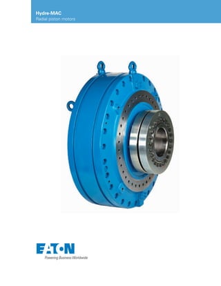
- 3. 3EATON Radial Piston Motor Catalog E-MOPI-CC002-E February 2016 Introduction Hydre-MAC™ Radial piston motor Direct drive variable speed machines benefit dramatically from Eaton’s new radial piston hydraulic motor. Class leading torque density decreases machine structural element costs, and reduces machine footprint. Superior mechanical efficiency further reduces energy consumption across a 2000:1 speed ratio while delivering full torque to the machine shaft. Over 90% stall torque efficiency allows the designer to avoid over-sizing the motor, and lowers overall maximum pressure requirements of the system. Applications Pulp and paper • Pulp washers • Digesters • De-barkers • Conveyors Mining • Bucket wheel reclaimers • Apron feeders • Breakers Recycling • Shredders Marine • Cutter wheel dredges • Winches Features and benefits • High Efficiency lowers operating costs • Replaceable wear surfaces lowers maintenance costs by extending maintenance intervals • Very low pressure drop delivers more output torque • Symmetrical design reduces uneven loading to increase operating life The low inertia design features enable instant stopping and reversing for highly dynamic applications and prevents torque spikes which could damage the machine elements and bearings. Shaft mounted and torque arm restrained features lowers coupling and mounting costs associated with extremely high torque applications. Multiple port configurations and locations offer the machine designer myriad solutions for the ultimate in flexibility. Integral multi-disc brake, torque arm kits and speed encoder options further expand the possibilities enabling the machine designer constraint free solutions.
- 4. 4 EATON Radial Piston Motor Catalog E-MOPI-CC002-E February 2016 Funtional description Eaton’s Hydre-MAC hydraulic motors are radial piston, cam lobe type. The housing is stationary, and can be mounted by a mechanical flange, foot or torque arm arrangement. Pressurized fluid, entering one or both of the inlet ports is directed thru the manifold housing thru a series of passageways and valve plate to sealed pistons, located in a rotating block called the rotor, or cylinder block. As oil is moving into the piston chamber, called the cylinder, or piston bore, the piston moves outward radially. The piston, in turn, pushes against a guide block called the crosshead assembly which has two rolling element bearings located on either end. These bearings roll down the cam slope causing rotation of the shaft. As the bearings roll down the cam slope, a reaction force is exerted upon the guide slot in the rotor through replaceable low friction plain bearing surfaces. After the pistons finish the extension stroke, the cam profile returns them to the starting position, and the oil flows outward from the pistons, thru the valve plate and manifold and out the return port.The rotor is connected to the shaft and as it rotates due to cam reaction forces, the output shaft rotates and exerts a rotational force on the machine shaft. Output torque is proportional to system pressure. Drain ports are supplied to allow leakage oil to exit the motor from the highest point, ensuring all bearings will remain submerged in lubricating oil. 1 4 6 9 12 10 15 11 14 7 13 8 2 3 5 1 Cam ring 2 Cam follower bearing 3 Crosshead assembly 4 Piston 5 Valve plate 6 Manifold 7 Rotor 8 Output shaft 9 Thrust bearing 10 Radial bearing 11 Output shaft bearing 12 Inboard shaft seal 13 Outboard shaft seals 14 Shrink disc coupling 15 Bearing plate
- 5. 5EATON Radial Piston Motor Catalog E-MOPI-CC002-E February 20165 Key technical differentiators Converting fluid power to rotating mechanical energy efficiently and reliably has proven to be challenging. Eaton’s Hydre-MAC radial piston motor was developed to overcome these challenges to deliver industry leading reliability, serviceability, efficiency and availability. Balanced design – long reliable operating life With 8 cam lobes and up to 18 pistons, the internal forces on the main bearings are balanced, freeing up the main bearings for external loads induced by mounting attitude and machine design. Constant flow cam ring profile – ultra smooth low speed performance increases efficiency The cam ring profile has been designed to eliminate torque ripple by preventing working piston overlap at the valve plate interface. In fact, each piston has significant dwell time at bottom and top of stroke while rotating, maintaining an equal number of pistons always doing work, resulting in constant displacement. Floating, sealed pistons – practically unlimited piston life and superior mechanical efficiency The pistons are designed to float in the bore, never side loaded, insuring reliabilty and long life. The floating design further increases mechanical efficiency by allowing all fluid power energy to be converted to linear motion, finally resulting in rotary motion with virtually no losses. Further, the piston seals are designed to prevent leakage which increases volumetric efficiency substantially. Large bearings – reliable long life All the main shaft bearings on the motor are over-sized for long life. The thrust bearing design does not require different oil than the system hydraulic fluid, and does not require flushing. All bearings are submerged in case oil under all installation conditions. Replaceable bearing plates – uncompromising serviceability The pistons push outward against a cross-head assembly containing the cam follower bearings. These crosshead assemblies slide in and out of the rotor slots on specially designed plain bearing surfaces, reducing friction, and converting linear motion to rotary motion without side-loading the pistons. These plain bearing surfaces, while replaceable, are designed to prevent catastrophic contamination related failure events by introducing a sacrificial element that can easily be replaced at low cost. This feature also enables reduced frequency low viscosity events, possibly caused by cooling system failure, without permanent damage to the motor. Valve plate – extremely high volumetric efficiency and very low case flow The valve plate is designed to prevent excess fluid flow and pressure loss by combining multiple features such as flatness, hardness, surface finish and balance. Precision ports large enough to pass very large amounts of fluid at nearly zero pressure drop further contribute to extremely high mechanical and volumetric efficiency. The precise balance of the design nearly eliminates excess case flow during high pressure events, and reduces the need for accumulators in highly dyamic applications such as shredders and other processing equipment Cam follower bearing diameter – reliable, predicable operating life Large diameter cam follower bearings lower cam surface stresses, ensuring very long cam life. Cam follower bearing life is easily calculated and is a very reliable indicator of operating life .
- 6. 6 EATON Radial Piston Motor Catalog E-MOPI-CC002-E February 2016 Specifications Units RCC1013 RCC1016 RCD1020 RCD1025 RCE1030 RCE1036 RCF1042 RCF1050 Displacement cc/rev (in3 /rev) 12789 (780) 16080 (982) 20160 (1231) 25320 (1546) 30580 (1867) 35460 (2165) 42180 (2575) 50670 (3093) Pressure Maximum1 Peak2 bar (psi) 350 (5075) 420 (6090) Speed Continuous Maximum3 Rpm 65 100 50 85 45 70 40 60 35 50 32 42 28 38 25 35 Torque Theoretical Nm/bar lb.ft/100psi 203 1031 255 1295 320 1625 402 2041 486 2467 563 2858 671 3406 805 4087 Power Continuous Peak3 kW (HP) 348 (467) 895 (1200) 337 (453) 798 (1070) 381 (511) 823 (1104) 425 (570) 887 (1189) 449 (602) 892 (1196) 476 (639) 869 (1165) 496 (665) 935 (1254) 531 (713) 1035 (1388) Case pressure Continuous Maximum bar (psi) 3.5 (50) 5 (72) Temperature Minimum Maximum °C (°F) -20 (-4) 75 (167) Charge Pressure Normal Dynamic braking4 bar (psi) 11 (160) 11 (160) 14 (201) 17 (247) 20 (290) 20 (290)14 (201) 17 (247) Hydraulic fluid Recommended operating viscosity range cSt (SUS) Minimum continuous viscosity Maximum Viscosity at startup cSt (SUS) FZG (90) Wear test according to DIN 51354, IP 334 Premium anti-wear hydraulic fluid 40-100 25 1000 Stage 11 pass 1 Continuous pressure above 250 bar requires flushing, specifically when operating more than 50% of continuous speed 2 Not to exceed 1% of duty cycle 3 Flushing required 4 At continuous speed
- 7. 7EATON Radial Piston Motor Catalog E-MOPI-CC002-E February 2016 Model code Motor size 013 016 020 025 030 036 042 050 1 2 3 4 Radial piston single cam ring motor RCC1 - C Frame (013, 016 displacements) • • X X X X X X RCD1 - D Frame (020, 025 displacements) X X • • X X X X RCE1 - E Frame (030, 036 displacements) X X X X • • X X RCF1 - F Frame (042, 050 displacements) X X X X X X • • 5 6 7 - Displacement 013 - 12,780 cc/rev (781 in3/rev) • X X X X X X X 016 - 16,080 cc/rev (982 in3/rev) X • X X X X X X 020 - 20,160 cc/rev (1231 in3/rev) X X • X X X X X 025 - 25,320 cc/rev (1546 in3/rev) X X X • X X X X 030 - 30,580 cc/rev (1867 in3/rev) X X X X • X X X 036 - 35,460 cc/rev (2165 in3/rev) X X X X X • X X 042 - 42,180 cc/rev (2575 in3/rev) X X X X X X • X 050 - 50,670 cc/rev (3093 in3/rev) X X X X X X X • 8 - Mounting interface M - Metric Pilot, UNC threaded • • • • • • • • 9 - Output shaft S - Hollow Shaft with Shrink Disc • • • • • • • • D - Solid Shaft, External Spline • • • • • • • • G - Solid Shaft, External Spline, both sides • • • • • • • • F - Hollow Shaft, Female spline • • • • • • • • 10 - Ports 1 - Opposite Side, 2" SAE J518 (code 62) UNC • • • • • • • • 2 - Opposite Side, 2" SAE J518 (code 62) Metric • • • • • • • • 11 - Brake 0 - Without Brake • • • • • • • • A - With Multi-disc brake • • • • • • • • Motor size 013 016 020 025 030 036 042 050 12 Flanged Valves 0 - No flanged valves • • • • • • • • 1 Cross port relief, dual acting • • • • • • • • 2 Brake release, internal hydraulic pilot • • • • • • • • 3 Brake release, internal electro-hydraulic pilot • • • • • • • • 4 Brake release, external hydraulic pilot • • • • • • • • 5 Counterbalance valve, 1 direction • • • • • • • • 6 Counterbalance valve, 2 directions • • • • • • • • 13 - Seals B - Standard - Nitrile (Buna-N) • • • • • • • • V - Fluorocarbon • • • • • • • • E - EPR • • • • • • • • 14 15 - Option not used 00 - No options • • • • • • • • 16 17 Special features 00 - None • • • • • • • • 01 - Under water shaft seal arrangement • • • • • • • • 02 - Without shrink disc coupling • • • • • • • • 18 - Paint 0 - No Paint (rust preservative coating) • • • • • • • • 1 - Eaton blue enamel topcoat • • • • • • • • 2 - Paintable primer only • • • • • • • • 3 - Eaton blue 2 part epoxy • • • • • • • • 19 - Nameplate 1 Eaton nameplate • • • • • • • • 20 - Design A - Design code A • • • • • • • • Standard part numbers Eaton model size Part number Model code Displacement Speed Power (max) Liters/rev in3 /rev Continuous Max kW HP RCC1013 995RC00001A RCC1013MS100B000011A 12.78 780 65 100 895 1200 RCC1016 995RC00003A RCC1016MS100B000011A 16.08 982 50 85 798 1070 RCD1020 996RC00001A RCC1020MS100B000011A 20.16 1231 45 70 823 1104 RCD1025 996RC00002A RCC1025MS100B000011A 25.32 1546 40 60 887 1189 RCE1030 997RC00001A RCC1030MS100B000011A 30.58 1867 35 50 892 1196 RCE1036 997RC00002A RCC1036MS100B000011A 35.46 2165 32 42 869 1165 RCF1042 998RC00001A RCC1042MS100B000011A 42.18 2575 28 38 935 1254 RCF1050 998RC00002A RCC1050MS100B000011A 50.67 3093 25 35 1035 1388 Note: • Preferred standard option • Special option on request X Not available RCC1 013 M S 1 0 0 B 00 00 1 1 A Series Displacement Mounting Interface Output Shaft Ports Brake Flanged valves Seals No Option Special Features Paint Name plate Design 1, 2, 3, 4 5, 6, 7 8 9 10 11 12 13 14, 15 16, 17 18 19 20
- 8. 8 EATON Radial Piston Motor Catalog E-MOPI-CC002-E February 2016 Graph indicates percentage of torque relative to differential pressure available at the output shaft. Graph indicates percentage of torque relative to differential pressure available at the output shaft when stalling occurs Graph indicates percentage of oil flow that passes thru the motor without contributing to rotation. 50% of indicated value is considered to be cross-port leakage with the remainder leaking to case. Mechanical efficiency vs. operating speed Stall torque efficiency vs. operating pressure Volumetric efficiency vs. operating pressure Performance – RCC1013 and RCC1016 0 1 5 10 20 30 40 55 70 90 110 130 90 95 96 97 98 99 100 Speed (rpm) Efficiency(%) RCC1016 RCC1013 RCC1016 Pressure (bar) 0 50 100 150 200 250 300 350 400 450 90 91 92 93 94 Efficiency(%) RCC1013 RCC1016 0 50 100 150 200 250 300 350 400 450 98.0 99.0 99.2 99.4 99.6 99.8 100.0 Pressure (bar) Efficiency(%) * Values shown are typical
- 9. 9EATON Radial Piston Motor Catalog E-MOPI-CC002-E February 2016 Graph indicates percentage of oil flow that passes thru the motor without contributing to rotation. 50% of indicated value is considered to be cross-port leakage with the remainder leaking to case. Performance – RCD1020 and RCD1025 Graph indicates percentage of torque relative to differential pressure available at the output shaft. Graph indicates percentage of torque relative to differential pressure available at the output shaft when stalling occurs Mechanical efficiency vs. operating speed Stall torque efficiency vs. operating pressure Volumetric efficiency vs. operating pressure 0 1 5 10 20 30 40 55 70 90 110 130 90 95 96 97 98 99 100 Speed (rpm) Efficiency(%) RCC1016 RCD1020 RCD1025 Pressure (bar) 0 50 100 150 200 250 300 350 400 450 90 91 92 93 94 Efficiency(%) RCD1020 RCD1025 0 50 100 150 200 250 300 350 400 450 98.0 99.0 99.2 99.4 99.6 99.8 100.0 Pressure (bar) Efficiency(%) * Values shown are typical
- 10. 10 EATON Radial Piston Motor Catalog E-MOPI-CC002-E February 2016 Performance – RCE1030 and RCE1036 Graph indicates percentage of torque relative to differential pressure available at the output shaft. Graph indicates percentage of torque relative to differential pressure available at the output shaft when stalling occurs Graph indicates percentage of oil flow that passes thru the motor without contributing to rotation. 50% of indicated value is considered to be cross-port leakage with the remainder leaking to case. Mechanical efficiency vs. operating speed Stall torque efficiency vs. operating pressure Volumetric efficiency vs. operating pressure 0 1 5 10 20 30 40 55 70 90 110 130 90 95 96 97 98 99 100 Speed (rpm)Efficiency(%) RCC1016 RCE1030 RCE1036 Pressure (bar) 0 50 100 150 200 250 300 350 400 450 90 91 92 93 94 Efficiency(%) RCE1030 RCE1036 0 50 100 150 200 250 300 350 400 450 98.0 99.0 99.2 99.4 99.6 99.8 100.0 Pressure (bar) Efficiency(%) * Values shown are typical
- 11. 11EATON Radial Piston Motor Catalog E-MOPI-CC002-E February 2016 Performance – RCF1042 and RCF1050 Graph indicates percentage of torque relative to differential pressure available at the output shaft. Graph indicates percentage of torque relative to differential pressure available at the output shaft when stalling occurs Graph indicates percentage of oil flow that passes thru the motor without contributing to rotation. 50% of indicated value is considered to be cross-port leakage with the remainder leaking to case. Stall torque efficiency vs. operating pressure Volumetric efficiency vs. operating pressure Mechanical efficiency vs. operating speed 0 50 100 150 200 250 300 350 400 450 98.0 99.0 99.2 99.4 99.6 99.8 100.0 Pressure (bar) Efficiency(%) 0 1 5 10 20 30 40 55 70 90 110 130 90 95 96 97 98 99 100 Speed (rpm) Efficiency(%) RCC1016 RCF1042 RCF1050 Pressure (bar) 0 50 100 150 200 250 300 350 400 450 90 91 92 93 94 Efficiency(%) RCF1042 RCF1050 * Values shown are typical
- 12. 12 EATON Radial Piston Motor Catalog E-MOPI-CC002-E February 2016 Requirements for back pressure (charge pressure) and boost pressure (supercharge pressure) Performance When motors are operating in braking mode or they are subjected to over-running load, to ensure correct operation, a charge pressure must be provided. The chart below provides information on the charge pressure requirement Volumetric loss – case drain flow rate The chart below shows typical case drain flow rates at 50 cSt Viscosity independent of speed. Drain flow is not a reliable indicator of useful life. Monitor reservoir cleanliness and viscosity. A good off-line filtration system is best value. Circulate continuously this clean oil thru the motor to wash out particles. Exact flow rate is not critical and typically 12-16 lpm (3-5 gpm) is adequate for any motor size. Capturing any magnetic particles by using a magnetic monitoring device, over time, gives best indication as to the health of the motor. Record the speed and pressure of the motor. Calculate, with the variables above, the projected life of the motor, using the bearing formulae from the bearing manufacturer. Remove the motor from service at 90% of calculated bearing life, and replace the bearings as needed. Additionally, bearing life formula are found in ATS-780, available from Eaton Engineering. Flow(litersperminute) 0 50 100 150 200 250 300 350 400 450 0 1 2 3 4 cSt Viscosity independent of speed. Pressure (bar) 42- 50L 30- 36L 20-25L 13- 16L The graph shows the minimum charge pressure which must be maintained at the low pressure (suction) port of the motor when acting as a hydrostatic braking unit (pumping mode). When using motors in normal driving mode it is advisable to maintain charge pressure minimum of 2 bar (30 psi). 0 10 20 30 40 50 60 70 80 90 100 110 2 5 10 15 20 25 30 Percentage of rated speed (rpm) Pressure(bar) 120 130 140 150 160 42-50 L 30-36 L 20-25 L 13-16L
- 13. 13EATON Radial Piston Motor Catalog E-MOPI-CC002-E February 2016 Performance Graph indicates pressure loss due to non-laminar flow inside the manifold at 50 cSt. This pressure is additive to charge pressure, but should not be sole source of charge pressure. No load pressure drop – motors from RCD1020 to RCD1025 0 5 10 15 20 25 30 0 5 10 15 20 25 30 35 40 45 50 55 60 65 70 75 80 85 90 95 100 105 110 115 120 Pressuredrop(bar) 16L 2 port 16L 4 port 13L2port 13L 4 por t Speed ( rpm) 0 1 2 3 4 5 6 7 8 9 0 5 10 15 20 25 30 35 40 45 50 55 60 65 70 75 80 Pressuredrop(bar) Speed (rpm) 25L 2 por t 25L 4 por t 20L 2 por t 20L 4 port No load pressure drop – motors from RCC1013 and RCC1016
- 14. 14 EATON Radial Piston Motor Catalog E-MOPI-CC002-E February 2016 Performance Graph indicates pressure loss due to non-laminar flow inside the manifold at 50 cSt. This pressure is additive to charge pressure, but should not be sole source of charge pressure. No load pressure drop – motors from RCF1042 to RCF1050 0 2 4 6 8 10 12 14 16 0 5 10 15 20 25 30 35 40 45 50 55 60 Pressuredrop(bar) Speed (rpm) 36L2port 36 L4port 30 L2port 30L 4 port 0 5 10 15 20 25 0 5 10 15 20 25 30 35 40 45 50 Pressuredrop(bar) Speed (rpm) 50L 2 port 50L 4 port 42L 2 port 42L 4 port No load pressure drop – motors from RCE1030 and RCE1036
- 15. 15EATON Radial Piston Motor Catalog E-MOPI-CC002-E February 2016 Dimensions RCC1013 with hollow shaft and shrink disc coupling RCC1016 with hollow shaft and shrink disc coupling 370. 0 [ 14. 57 ] 370. 0 [ 14. 57 ] 370. 0 [14. 57] 460. 0 [ 18. 11 ] 460. 0 [ 18. 11 ] Ø 905. 0 [ 35. 63 ] Ø794. 9 [31. 29] Ø530. 0 [20. 86] Ø180. 0 7. 09[ ] Ø405. 0 [15. 94] 120. 0 [4. 724 ] 10. 0 [ 0. 39 ] 54. 0 [ 6. 06 ] 12. 0 [ 0. 47 ] 202. 0 [ 7. 95 ] 370. 0 [ 14. 57 ] 505. 0 [ 19. 88 ] 707. 0 [ 27. 83 ] ( To front of Shaft) 141. 0 [ 5. 55 ] C. O. G 140. 0 [ 5. 51 ] 70. 0 [ 2. 76 ] 245. 0 [ 9. 65 ] 245. 0 [ 9. 65 ] Ø794. 9 [31. 29] Ø460.0 [18. 11] Ø155.0 [6. 10] Ø 405. 0 [15. 94] 84. 0 [3. 31] 10. 0 [ 0. 39 ] 12. 0 [0. 47] 138. 0 [ 5. 43 ] 186. 0 [ 7. 32 ] 691. 0 [ 27. 20 ] ( To front of Shaft) 141. 0 [ 5. 55 ] C. O. G 370. 0 [ 14. 57 ] 505. 0 [ 19. 88 ] 140. 0 [ 5. 51 ] 70. 0 [ 2. 76 ] 370. 0 [ 14. 57 ] 370. 0 [ 14. 57 ] 370. 0 [14. 57] 460. 0 [ 18. 11 ] 460. 0 [ 18. 11 ] Ø 905. 0 [ 35. 63 ] 245. 0 [ 9. 65 ] 245. 0 [ 9. 65 ]
- 16. 16 EATON Radial Piston Motor Catalog E-MOPI-CC002-E February 2016 Dimensions RCD1020 and RCD1025 with hollow shaft and shrink disc coupling RCE1030 and RCE1036 with hollow shaft and shrink disc coupling Ø430.0 [16.93] 140. 0 [5. 51] Ø530. 0 20. 86 160. 0 [6.30] 80. 0 [3. 15] 455. 0 [17. 91] 214. 55 [8. 447] C.O.G 160. 9 [6. 34] 15. 0 [0. 59] 804. 0 [31. 65] To front of Shaft 265. 0 [10. 43] Ø1110. 0 [43. 70] Ø200.0 [7.87] 643 [25. 3] 492 [19. 37] 455. 0 [17. 91] 265. 0 [10. 43] 455. 0 [17. 91] 455. 0 [17. 91] 170. 0 [6. 69] 506. 0 [19. 92 ] 510. 0 [20. 08] Ø1005. 0 [ 39. 57 ] Ø1005. 0 [ 39. 57 ] 510. 0 [ 20. 08 ] Ø700.0 [27. 56] Ø260.0 [10. 24] Ø570. 0 [22. 44] 854. 0 [33. 62] (To front of Shaft) 657. 0 [25. 87] 197. 0 [7. 76] 14. 5 [0. 57] 203. 03 [7. 993] C.O.G 80. 0 [3. 15] 160. 0 [6. 30] Ø1220. 0 [48. 03] 265. 0 [10. 43] 510. 0 [20. 08] 510. 0 [20. 08] 265. 0 [10. 43]
- 17. 17EATON Radial Piston Motor Catalog E-MOPI-CC002-E February 2016 Dimensions RCF1042 and RCF1050 with hollow shaft and shrink disc coupling 575. 0 [22. 64] 575. 0 [22. 64] Ø700.0 [27. 56] Ø 570. 0 [ 22. 44 ] Ø260.0 [10. 24] 170. 0 [6. 69 ] 866. 0 [ 34. 09 ] (To front of Shaft) 197.0 [7. 76 ] 14. 5 [ 0. 57 ] 212. 04 [ 8. 348 ] C.O.G 518. 0 [ 20. 39 ] 80. 0 [ 3. 15 ] 160. 0 [6. 30 ] 669. 0 [26. 34] Ø1350. 0 [ 53. 15 ] 575. 0 [ 22. 64] 575. 0 [ 22. 64] 265. 0 [10. 43] 265. 0 [10. 43] Hydre-MAC motor Dimension mm (inch) Series A B C RCC1013 154.986/154.946 [6.1018/6.1002] 89.00 [3.50] 149.0 [5.87] RCC1016 179.986/179.946 [7.0860/7.0845] 120.0 [4.72] 174.0 [6.85] RCD1020 – RCD1025 199.985/199.939 [7.8734/7.8716] 150.0 [5.91] 194.0 [7.64] RCE1030 – RCE1036 RCF1042-RCF1050 259.983/259.931 [10.2355/10.2335] 190.0 [7.48] 254.0 [10.00] Motor weights Motor weights with shrink disc Series kg [lbs] RCC1013 - RCC1016 1350 [2976.24] RCD1020 - RCD1025 2125 [4684.82] RCE 1030 – RCE1036 2760 [6084.76] RCF 10342 – RCF1050 3240 [ 7142.98] Driven shafts Machine shafts should be constructed of alloy steel with minimum yield strength greater than 65,000 psi R 50. 0 [1. 97] Ø17.0 [0. 67] 16.0 ± 0.5 [0.24 ± 0.02] 50.8 [2.00] 3.2 ØC ØA M20 5/8”-11 UNC 25.4 1. 00” 30° B or
- 18. 18 EATON Radial Piston Motor Catalog E-MOPI-CC002-E February 2016 Optional accessories torque arm kit Torque arm Motor Torque arm kit Dimensions mm [inches] Model Model number Part number A B C D TACC RCC1013 9901120-000 800 [31.50] 355 [13.98] 80 [3.15] 200 [7.87] TACD RCC1016, RCD1020, RCD1025 9901121-000 1250 [49.21] 465 [18.30] 80 [3.15] 200 [7.87] TAEF RCE1030, RCE1036 RCF1042, RCF1050 9901122-000 1500 [59.05] 465 18.30] 80 [3.15] 200 [7.87] Item Description Qty 1 Torque arm 1 2 Anchor 1 3 Pin 2 4 Pivot link 1 5 Washer 2 6 Retaining ring 2 Torque arm Series C.O.G. mm [inch] Weight kg[lbs] TACC 237.24 [9.340] 93.4 [205.92] TACD 483.82 [19.048] 129.8 [286.16] TAEF 507.38 [19.975] 186.2 [410.50] 1 3 4 2 5 6 A B C D C.O.G
- 19. 19EATON Radial Piston Motor Catalog E-MOPI-CC002-E February 2016 Optional accessories Encoders Standard encoder kit Avtron sensor (includes encoder and all mounting hardware Avtron model: A6VM A 6 C 2 A A 5 K 000 12 bit, 4096 ppr, 4-20mA Option retrofit kit L+B sensor (includes all mounting hardware, without encoder) 9901027-001 For 20-50L motors 9901027-003 For 13-16L motors 9901027-000 For 20-50L motors 9901027-002 For 13-16L motors
- 20. 20 EATON Radial Piston Motor Catalog E-MOPI-CC002-E February 2016 Hydraulic fluid selection Hydre-MAC motors are generally intended for operation on conventional petroleum based oils, which should contain additives to improve the anti-wear performance, oxidation resistance, corrosion protection and foam suppression properties. The oil must have FZG (90) fail stage minimum 11 described in IP 334 (DIN 51354). The water content must be less than 0.1%. General recommendations Oil viscosity will vary considerably with temperature, it is important therefore to choose an operating fluid which will give the required viscosity at the expected system operating temperature. It should be noted that high system temperatures may cause a deterioration of the hydraulic fluid resulting in reduced lubrication properties and a consequent reduction in motor and seal life. In installations where motors are in continuous operation it may be necessary (due to the relatively low internal leakage) to provide a flow of approximately 5 liters/min of clean filtered system fluid through the motor casing for cooling purposes by utilizing two of the drain ports. With high environmental temperatures and with the motor in continuous operation it may be necessary to incorporate a cooler in the circuit to keep the oil viscosity within the recommended limits. Fluid cleanliness Experience has shown that failures that occur in hydraulic equipment are frequently attributable to the presence of contamination in the system. Before connecting the hydraulic motor to the system all hoses, fittings and pipework must be thoroughly cleaned and the fluid filtered. Non-welded type piping systems are preferred. Where welded pipe is utilized, proper cleaning procedures must be followed, including record stating the ISO cleanliness level achieved before starting the system. It is recommended that the contamination level be kept within ISO 4406 16/13 (NAS 7) and should not exceed ISO 4406 19/15 (NAS 10). The hydraulic system must be continuously filtered to this level during operation. Temperature It is recommended that motors are operated within the values given below. The values reflect case temperature . Recommended Temperature Range 25°C to 50°C. Maximum Operating Temperature +75°C. Minimum Operating Temperature -20°C. Operation above the maximum or below the minimum operating temperature may cause permanent damage. Fire resistant fluids When Hydre-MAC motors are to operate on fire resistant (FR) or high water based fluids (HWBF) some limitations will apply. Depending on the fluid to be used there may be changes to the motor construction or limitations to the speed and pressure ratings as well as changes to seal materials. The table below gives a summary of the requirements. Case flushing Hydre-MAC motors have extremely high volumetric efficiency which reduces the leakage oil. Operating Hydre-MAC motors above 50% of rated speed and/or 200 bar necessitates additional flushing oil to be introduced into the lower case drain port to maintain case temperature requirements. The oil should be clean and cooler than loop oil (avoid using oil flushed out of the loop thru a hot-oil shuttle valve, unless loop temperature is within desired operating limits) and of sufficient flow rate to keep the motor case within normal operating temperature range. Application information Viscosity at normal operating temperatures 40 - 100 cSt Minimum viscosity in operation 25 cSt Maximum viscosity in operation 1000 cSt Flash point Not below 170°C Pour point -30° C Normal operating system temperature range 15° - 60° C Fluid Motor construction Maximum pressure (bar) Maximum speed (rpm) Life factor Seal material OX40 HWBF Version 250 Not to exceed motor rated speed 0.10 Standard (nitrile) Water Glycol HWBF Version 250 Not to exceed motor rated speed 0.20 Standard (nitrile) 5/95 Oil-in- water dilute emulsion HWBF Version 200 Not to exceed motor rated speed 0.10 Standard (nitrile) 40/60 Water-in- oil emulsion Standard 200 Standard motor ratings apply 0.50 Standard (nitrile) Phosphate Esters Standard 350 Standard motor ratings apply 0.50 Special (Viton)
- 21. 21EATON Radial Piston Motor Catalog E-MOPI-CC002-E February 2016 For additional application assistance, please fill out the requested information below and submit to IndustrialDrivesAE@eaton.com for a timely and thorough response. Customer name Project name Application name Duty cycle parameters: (for constant duty cycle, use single operation) Application data sheet Environment Elevation Coating requirements Brake torque Brake actuation duty cycle Parameter Units Operation 1 Operation 2 Operation 3 Operation 4 Operation 5 Speed Rpm Continuous pressure bar (psi) Time fraction % Oil temperature ºC Charge pressure bar Viscosity cSt _________________________________________________________________________________________ ____________________________________________________________________________________________ ______________________________________________________________________________________________ ____________________________________________________________________________________ __________________________________________________________________________________________ ________________________________________________________________________________ ___________________________________________________________________________________________ _______________________________________________________________________________________
- 22. Eaton Hydraulics Group USA 14615 Lone Oak Road Eden Prairie, MN 55344 USA Tel: 952-937-9800 Fax: 952-294-7722 www.eaton.com/hydraulics Eaton Hydraulics Group Europe Route de la Longeraie 7 1110 Morges Switzerland Tel: +41 (0) 21 811 4600 Fax: +41 (0) 21 811 4601 Eaton Hydraulics Group Asia Pacific Eaton Building 4th Floor, No. 3 Lane 280 Linhong Rd. Changning District Shanghai 200335 China Tel: (+86 21) 5200 0099 Fax: (+86 21) 5200 0400 © 2016 Eaton Corporation All Rights Reserved Printed in USA Document No. E-MOPI-CC002-E February 2016