1.
Modeling Stormwater Infiltration in Roadside Swales
Anthony Vecchi
Submitted under the supervision of Dr. John Gulliver to the University Honors Program at the
University of Minnesota-Twin Cities in partial fulfillment of the requirements for the degree of
Bachelor Science, Summa Cum Laude in Civil Engineering.
4/30/2015
3.
Abstract
Swales are stormwater best management practices used to carry stormwater runoff from roads
into the stormwater sewer system. Recent research suggests that swales may serve not only as
stormwater conveyance devices, but also as infiltration devices. Past research by Deletic (2001)
shows that models can be created to estimate the infiltration capacity of swales by assuming that
runoff flows off the road and down the side slope of the swale as a sheet flow. This thesis
investigates how the sheet flow assumption may be avoided by creating a model that routes flow
over a fraction of the side slope using a parameter referred to as ‘fractionally wetted area’. This
model has been developed using Matlab software and is formulated using a numerical solution of
the Green-Ampt infiltration along with numerical solutions of the overland flow. The results of
this model have been compared to three model studies and a field experiment. The comparison
showed that the accuracy of the model is limited by the accuracy of the inputs relating to the soil
parameters of the swale.
4.
Table of Contents
1
Introduction
.......................................................................................................................................
1
1.1
Review
........................................................................................................................................................
2
2
Model Development
.........................................................................................................................
4
2.1
Model Equations
......................................................................................................................................
5
2.2
Model Structure
.......................................................................................................................................
7
3
Physical Experiments
....................................................................................................................
11
4
Results
..............................................................................................................................................
14
5
Conclusions
.....................................................................................................................................
19
6
References
.......................................................................................................................................
20
Appendix
A
.........................................................................................................................................
A-‐1
6.2
Model Trial Inputs
..............................................................................................................................
A-‐1
6.3
Matlab Model
.......................................................................................................................................
A-‐2
5.
Table of Tables
Table 1 : Model Input Parameters
......................................................................................................
9
Table 2 : Flume Model Study Results
..............................................................................................
12
Table 3 : Selected Field Experiment Results
..................................................................................
13
Table 4 : Model Results
......................................................................................................................
14
Table 5 : Revised Model Results using adjusted ks
......................................................................
17
Table A1 : Trial 1
...............................................................................................................................
A-‐1
Table A2 : Trial 2
...............................................................................................................................
A-‐1
Table A3 : Trial 3
...............................................................................................................................
A-‐1
Table A4 : Field Experiment Trial
.................................................................................................
A-‐2
Table of Figures
Figure
1 : Flume Model Study
..........................................................................................................
12
Figure
2 : Field Experiments at Hwy 51
........................................................................................
13
Figure
3 : Modeled specific discharge at the bottom of the side slope for Trial 1
................
15
Figure
4 : Modeled specific discharge at the bottom of the side slope for Trail 2
................
15
Figure
5 : Modeled specific discharge at the bottom of the side slope for Trial 3
................
16
Figure
6 : Modeled specific discharge at the bottom of the side slope for the Field
Experiment
............................................................................................................................................
16
Figure
7 : Modeled specific discharge at the bottom of the side slope for Trial 1 with ks
changed from the estimated 12.83 cm/hr to 8 cm/hr
....................................................................
17
Figure
8 : Modeled specific discharge at the bottom of the side slope for Trial 2 with ks
changed from the estimated 12.83 cm/hr to 8 cm/hr
....................................................................
18
Figure
9 : Modeled specific discharge at the bottom of the side slope for Trial 3 with ks
changed from the estimated 12.83 cm/hr to 8 cm/hr
....................................................................
18
6. Vecchi 1
1 Introduction
The Pollution Prevention program led by the Minnesota Pollution Control Agency (MPCA) has
the goal of reducing nutrient loading on Minnesota’s lakes and rivers, thereby reducing future
costs associated with pollution. The MPCA’s Minnesota Stormwater Manual lays out several
devices, called stormwater Best Management Practices (BMPs), which can be used for
stormwater volume reduction and/or nutrient removal (MPCA, 2014). Documentation for each
BMP includes design guidelines and estimated performance in terms of volume reduction, total
suspended solids (TSS) removal, total phosphorous (TP) removal, and total nitrogen (TN)
removal. The MPCA may award pollution prevention credits to parties that successfully
implement and maintain a BMP. The extent of these credits is dependent on the type of BMP
chosen and its corresponding removal/reduction estimates.
Swales are grassed (or otherwise vegetated) channels used as a stormwater BMP to capture
stormwater runoff and route it elsewhere, typically to a storm sewer. A swale’s primary
stormwater treatment capability is in filtering solids from the flow as it passes over the grass in
the channel. The infiltration capacity of swales is acknowledged in the MPCA’s Stormwater
Manual, but there is no effort to quantify the expected volume reduction due to infiltration as
stormwater runs off a road and into the center of a swale. For this reason, owners of swales,
including the Minnesota Department of Transportation, may not be getting enough pollution
prevention credits for the infiltration taking place in their swales.
7. Vecchi 2
The properties of a swale that affect its infiltration capacity are complex and carry with them
substantial uncertainty. These properties include initial soil moisture content, saturated hydraulic
conductivity, effective wetting front suction, and fraction wetted (a parameter to be introduced
later in this paper). Due to this reality, translating the physical conditions into a mathematical
model can be challenging. This has led to the MPCA relying on the Minimal Impact Design
Standards (MIDS) Calculator, an empirical tool, to estimate infiltration in swales. The goal of
this thesis is to model stormwater infiltration as runoff flows down the side slope of a swale
without assuming that the runoff will flow as a sheet.
1.1 Review
Other studies have approached the problem of infiltration in grassed swales using more rigorous
methods. A study by Deletic (2001) dealt most directly with sediment transport, but dealt with
infiltration mathematically. In this study, Deletic used the Green-Ampt method to estimate
infiltration, the kinematic wave equation to model overland flow, and incorporated the effects
that sediment deposition could have on the terrain of the swale slope. The model was created
using TRAVA and was calibrated against known sedimentation behavior. The model results
represent a hypothetical swale’s behavior and were not compared to physical results. The model
also assumes that runoff travels down the slope as a sheet flow.
Deletic and Fletcher (2005) conducted a field and modeling study regarding stormwater flow
down the center of a swale. The focus of this study was suspended sediment removal, but the
8. Vecchi 3
TRAVA model employed did account for infiltration. This model was able to accurately estimate
swale outflow, but only after measured results were used to calibrate the infiltration parameter
saturated hydraulic conductivity (ks). In other words, stormwater volume reduction could only be
estimated for a swale if extensive field studies were done to determine its infiltration
performance. As before, this model is based on the assumption that runoff flows down the
swale’s side slope as a sheet.
The goal of this study is to develop a simple and accurate model to predict the volume reduction
of stormwater traveling down the side slope of a swale during a certain storm based on physical,
measurable swale parameters. This model will consider the fact the runoff down a slope will not
occur as a sheet flow, but will only pass over a fraction of the slope area. This fact manifests
itself in the form of the ‘fractionally wetted area’ parameter. Generally, the model presented in
the following section may be implemented to develop improvements in relations used in the
MIDS Calculator to determine volume reduction and to make decisions regarding pollution
prevention credits.
9. Vecchi 4
2 Model Development
The model simulates stormwater runoff flowing off of a paved road and down the slope of a
swale into its channel. The model relies on the assumption that there is no standing water on the
slope of the swale prior to the beginning of the rain event. This is an acceptable assumption
because the relatively steep slope inhibits the accumulation of water. The output of the model is
the runoff at the bottom of the slope over the duration of the storm as well as the volume of rain,
volume of runoff, and percent volume reduction during the storm. It should be noted that the
accuracy of the outputs is limited most directly by the accuracy of the input soil parameters
(most notably ks). Other errors incurred by the model include those associated with an iterative
solving method. However, this error tends to be on the order of 1% of the volume of rain.
The model solves for infiltration using the Green-Ampt assumptions, the Manning’s Equation,
and a simple mass balance in each cell moving down the slope at discretized time steps
throughout the duration of the storm. The key to differentiating this model from others (Deletic
2001, 2005) is the use of a fractionally wetted area in mass balance and infiltration computations.
Fractionally wetted area (fw) refers to the percent of slope area passed over by runoff due to the
natural, small-scale terrain of the slope’s surface. Natural rills and surface depressions mean that
the assumption that runoff will flow over the slope as a sheet flow is inappropriate and could
lead to an over-estimation of the amount of infiltrated runoff.
10. Vecchi 5
2.1 Model Equations
The first step in the model is to discretize the slope into cells in the direction of the slope. The
model includes a routine to select an optimized time-step that reduces model computation errors
by ensuring that the Courant number does not exceed 1. The computations of the model begin by
computing runoff from the contributing road surface. The cell index is given by k, qin represents
the specific discharge into the top of the cell, ir represents the rainfall intensity over the road, i
represents the rainfall intensity over the swale, w represents the contributing width in the
direction parallel to the swale slope of the road, Δy represents the length of the cells in the
direction parallel to the swale slope, and fw is the fractionally wetted area for the cell. The
effective rainfall intensity (ie) may be computed as shown below.
𝑖!,! =
!!",!
∆!
+ 𝑖 (1)
For infiltration calculations, ie will be used to estimate the flow entering the top of each cell in
each time step that may be infiltrated. In other words, the maximum infiltration rate is limited by
ie instead of i. Following the method for ponding during an unsteady rain, the ponding time is
computed for each cell as soon as water reaches that cell (Chu, 1978). The current time, relative
to the ponding time, determines the infiltration rate.
𝑡! =
!!!!!
!!,!!!!
!!!!!,!!!!!!,!
!!,!
+ 𝑗 − 1 ∆𝑡 (2)
𝑓! = 𝑖!,! 𝑖𝑓 𝑗!"#$",! − 𝑗 Δ𝑡 ≤ 𝑡! (3)
𝑓! = 𝑘!
!!!
!!!!,!
+ 1 𝑖𝑓 𝑗!"#$",! − 𝑗 Δ𝑡 > 𝑡! (4)
𝐹!,! = 𝐹!!!,! + 𝑓!,!∆𝑡𝑓!,! (5)
11. Vecchi 6
In these equations, tp is the time of ponding, ks is the saturated hydraulic conductivity, ψ is the
initial effective wetting front suction head, Δθ is the change in moisture content, P is the
cumulative rainfall for a certain cell (in terms of effective intensity), R is the cumulative runoff
for a certain cell, f is the Green-Ampt infiltration rate, F is the cumulative infiltration, j is the
time step index, jstart is the time index at which water enters a certain cell, and Δt is the time step.
The infiltration is converted into an equivalent specific discharge, qinf into the soil with the
relation:
𝑞!"#,! = 𝑓!∆𝑦 (6)
Next, a mass balance is used to determine the flux of water in each cell at each time step. As
mentioned earlier, this mass balance assumes that all water enters the top of the cell. This is a
reasonable assumption due to the relatively small size of the cells.
𝑂𝑢𝑡𝑓𝑙𝑜𝑤 = 𝐼𝑛𝑓𝑙𝑜𝑤 − 𝐼𝑛𝑓𝑖𝑙𝑡𝑟𝑎𝑡𝑖𝑜𝑛 −
𝑑𝑉
𝑑𝑡
(7)
or
𝑞!"#,! = 𝑞!",! − 𝑞!"#,! + 𝑖∆𝑦 −
∆!!,!∆!
∆!
(8)
where V is volume of water on the soil surface in the cell and qout is the specific discharge from
the cell. In this equation, Δh represents the change in depth of runoff in that cell during that time
step. The current depth of runoff in a cell during a certain time step is given by rearranging
Manning’s equation in the following manner:
ℎ!,! =
!!!"#,!
!.!
!!.!
(9)
12. Vecchi 7
where S represents the side slope of the swale and n is Manning’s roughness coefficient. The
Manning’s n value is selected based on the vegetation lining the swale. Next, the change in depth,
Δhj,k, can be computed in the following manner.
∆ℎ!,! = ℎ!,! − ℎ!!!,! (10)
Finally, the Courant, Cou, number may be computed for each cell at each time step using the
following equation.
𝐶𝑜𝑢!,! =
!!"#,!
!!,!
∆!
∆!
(11)
The relationship between the outflow of a cell and the inflow of the cell below it is related to the
fractionally wetted area in the following manner.
𝑄!"#,! = 𝑞!"#,!∆𝑥𝑓!,! (12)
𝑞!",! =
!!"#,!!!
∆!!!,!
(13)
Where Δx represents the length of the modeled swale in the direction of the contributing road.
2.2 Model Structure
The model is constructed in a linear way using Matlab software, evaluating each cell
successively for each time step. Initially, the model includes routines that convert all inputs into
the base SI units for further calculations. The body of the model follows the following
progression, outlined by the list shown below.
Begin loop through time (index: j)
Begin loop through space (index: k)
13. Vecchi 8
• Evaluate equation (1) if k=1, equation (13) if k>1
• Evaluate equation (2)
• Evaluate equation (3)
• Evaluate equation (4) or (5)
• Evaluate equation (6)
• Evaluate equation (7)
• Iteratively solve:
o Equations (8), (9), and (10)
• Evaluate equation (11)
• Evaluate equation (12)
End loop through space (index: k)
End loop through time (index: j)
The iterative solution for qout, h, and Δh can incur error into the final result. This effect is
mitigated by imposing an iterative tolerance on Δh of 0.0000005 m. Methods are implemented
into the model to improve convergence of this iterative process by improving the guesses for Δh.
The effectiveness of this iteration is related to the Courant number. Lower Courant number
results in the need for more iterations, and often larger errors. Similarly, results of the model
with Courant numbers >1 are suspicious, as this implies that flow is traveling over multiple cells
in a single time step. A routine has been installed into the model to select a time step that results
in the maximum Courant number falling between 0.9 and 1. Ultimately, this leads to a more
robust model because the user need not worry about selecting a valid time step.
14. Vecchi 9
Lastly, the model creates a plot of discharge at the bottom of the slope over the duration of the
storm. This helps the user visualize when flow will begin to appear into the swale’s channel, and
the steady state discharge into this channel. The model also reports the total inflow being
imposed on the swale and total volume of runoff. Errors in the model (due to the iterative
solution) are determined by subtracting the total outflow volume during the storm from the total
inflow volume.
The model requires several inputs that represent physical, measurable quantities, given in Table
1.
Table 1: Model Input Parameters
Parameter Unit
Rainfall intensity over road (ir) in/hr
Rainfall intensity over swale (i) in/hr
Length of slope (L) m
Number of cells down slope -
Duration of storm event hr
Effective wetting front suction (ψ) cm
Change in soil moisture (Δθ) -
Saturated Hydraulic Conductivity (ks) cm/hr
Length of road in direction of slope (w) m
15. Vecchi 10
Width of swale (Δx) m
Fraction wetted (fw) -
Side slope (S) -
Manning’s n (n) -
16. Vecchi 11
3 Physical Experiments
A set of laboratory and field experiments was conducted by Ms. Maria Garcia-Serrana at the
University of MN, working under the direction of Dr. John Gulliver and Dr. John Nieber. Ms.
Garcia-Serrana conducted this study to determine how fractional coverage of flow down the side
slope of a swale affects its capacity to infiltrate (Garcia-Serrana, 2015). The study included 3
trials using a full-scale model built at the St. Anthony Falls Laboratory and field experiments
using swales across the Twin Cities Metro area.
For the model study, a full-scale 1:6 slope was built using compacted loamy sand. For each trial,
water was added to the top of the slope for 60 minutes at a rate equivalent to a 2.5 cm/hr rain
event. Data collected from each trial includes volume of water infiltrated (measured using
drainage pipes installed below the soil), volume of runoff, micro-topography of the surface, and
wetted surface area. For the first trial, the slope was smoothed with a trowel before testing. For
the second trial, 3 semi-circular incisions were made along the length of the slope using a 1.8”
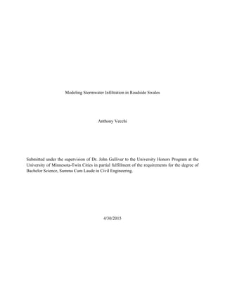
diameter pipe (Figure 1). The third trial had 5 semi-circular incisions of the same style. The
results of the model study can be found in Table 2.
17. Vecchi 12
Figure
1: Flume Model Study
Table 2: Flume Model Study Results
Trial # of Rills Input Water Volume (L) Runoff Volume (L)
1 0 234 123.3
2 3 234 157.5
3 5 234 164.5
The field experiments included 4 trials at swale locations across the Twin Cities area (Hwys 13,
47, 55, and 77). An example illustration is given in Figure 2. For each trial, the surface
vegetation was trimmed and the surface roughness was measured using a pin meter. A discharge
equivalent to a 5.6 cm/hr rain event was applied at the top of the swale for 30 minutes for each
18. Vecchi 13
trial. For this study the total runoff volume, micro-topography of the swale, the intensity of
runoff, and the wetted surface area over time were measured. For this report, only the results of 1
of the field trials will be considered. The results of this trial can be found in Table 3.
Figure
2: Field Experiments at Hwy 51
Table 3: Selected Field Experiment Results
Trial Input Water Volume (L) Runoff Volume (L)
1 255.4 89.9
19. Vecchi 14
4 Results
The Matlab model was run using inputs to simulate each of the 3 flume model trials and the
selected field experimental trial. The input parameters used in the model were taken directly
from the results of the physical measurements made on the compacted laboratory soil. These
inputs, for each model run, may be found in the appendix. The model results shown in Table 4
and Figure 3, Figure 4, Figure 5 and Figure 6 compare modeled runoff volumes with the
measured runoff volumes, as well as show the runoff intensity (as a specific discharge) over the
course of the simulated storm. A second set of model trials for the flume study using a lower ks
value (8 cm/hr instead of the measured 12.83 cm/hr) is given in Table 5 and Figure 7, Figure 8,
and Figure 9 to demonstrate the affect that the saturated hydraulic conductivity has on the model
results and to consider an alternative estimate to the ks value.
Table 4: Model Results
Trial
Input Water Volume
(L)
Runoff Volume
(L)
Model Runoff Volume
(L)
Model Mass Balance
Error (L)
1 234 123.3 65.5 0.3
2 234 157.5 91.3 1.8
3 234 164.5 106.5 0.2
Field 255.4 89.9 177.6 0.4
20. Vecchi 15
Figure
3: Modeled specific discharge at the bottom of the side slope for Trial 1
Figure
4: Modeled specific discharge at the bottom of the side slope for Trail 2
21. Vecchi 16
Figure
5: Modeled specific discharge at the bottom of the side slope for Trial 3
Figure
6: Modeled specific discharge at the bottom of the side slope for the Field Experiment
22. Vecchi 17
Table 5: Revised Model Results using adjusted ks
Trial
Input Water Volume
(L)
Runoff Volume
(L)
Model Runoff Volume
(L)
Model Mass Balance
Error (L)
1 234 123.3 121.1 0.3
2 234 157.5 138.4 1.2
3 234 164.5 148.1 0.2
Figure
7: Modeled specific discharge at the bottom of the side slope for Trial 1 with ks changed from
the estimated 12.83 cm/hr to 8 cm/hr
23. Vecchi 18
Figure
8: Modeled specific discharge at the bottom of the side slope for Trial 2 with ks changed from
the estimated 12.83 cm/hr to 8 cm/hr
Figure
9: Modeled specific discharge at the bottom of the side slope for Trial 3 with ks changed from
the estimated 12.83 cm/hr to 8 cm/hr
24. Vecchi 19
5 Conclusions
The goal of the Matlab model is to predict runoff, for a given storm, along the side slope of a
swale with overland flow that covers a fraction of the slope surface. The model developed has
proven to be robust and computationally accurate. The results of the model analysis show,
however, that the validity of the model’s ability to predict infiltration and runoff depends on the
accuracy of the model’s inputs. For example, this study also indicates that the model was
sensitive to infiltration parameters such as ks.
The fraction wetted parameter also has uncertainty associated with it. Flume studies at Saint
Anthony Falls Laboratory indicate that the fw parameter may vary both in space and time over
the course of a storm. This effect was not measured in the study, and was therefore not included
in the model. In reality, the runoff may flow closer to a sheet during the early stages of a storm
before developing rills and reaching a steady state fraction of coverage.
Future research may be undertaken to develop greater accuracy in estimating physical parameters
such as ks and fw. The model trials show that manipulating inputs such as these can yield model
results that closely simulate the behavior observed in physical experiments. Eventually, this
method may be employed to estimate volume reduction in swales during a given storm. This
would allow agencies such as the MPCA to better distribute Pollution Prevent credits and to use
a version of this model to establish infiltration rates for various swales in the MIDS Calculator.
25. Vecchi 20
6 References
Chu,
S.
T.
(1978).
Infiltration
During
an
Unsteady
Rain.
Water
Resources
Research
,
14
(3),
461-‐466.
Deletic,
A.
(2001).
Modelling
of
water
and
sediment
transport
over
grassed
areas.
Journal
of
Hydrology
(248),
168-‐182.
Deletic,
A.,
&
Fletcher,
T.
D.
(2005).
Performance
of
grass
filters
used
for
stormwater
treatment
-‐
a
field
and
modelling
study.
Journal
of
Hydrology
(317),
261-‐275.
Garcia-‐Serrana,
M.
(2015,
March).
Infiltration
into
Roadside
Drainage
Ditches.
UPDATES
,
10.2
.
Minneapolis,
Minnesota,
United
States
of
America.
MPCA.
(2014).
Minnesota
Stormwater
Manual.
Retrieved
March
28,
2015,
from
Minnesota
Stormwater
Manual
Wiki:
http://stormwater.pca.state.mn.us/index.php/
27. Vecchi A-‐2
Table A4: Field Experiment Trial
6.3 Matlab Model
Time step selection routine
T=10000; % Number of time steps
max_Cou=slope_runoff( ir,i,length,rows,duration,T,psi,deltheta,ks,w,x,fw,S,n
);
while max_Cou>1 || max_Cou<0.9
T=round(T*max_Cou);
max_Cou=slope_runoff( ir,i,length,rows,duration,T,psi,deltheta,ks,w,x,fw,S,n
);
end
Green-Ampt Infiltration routine
function [ f ] = Green_Ampt_rate( psi,deltheta,ks,ie,tstep,F,j,jstart,P,R )
X=psi*deltheta;
tp=(((ks*X/(ie-ks))-P+R)/ie)+(j-1-jstart)*tstep;
if tp>(j-jstart)*tstep
f=ie;
else
if (j-jstart)==0
f=ie;
else
f=ks*(X/F+1);
end
end
if f>ie
f=ie;
end
end
Runoff routine
function [ max_Cou ] = slope_runoff(
28. Vecchi A-‐3
ir,i,length,rows,duration,T,psi,deltheta,ks,w,x,fw,S,n )
%% Unit conversions
ir=ir*2.54/360000; % Converts to m/s
i=i*2.54/360000; % Converts to m/s
dy=length/rows;
duration=duration*3600; % Converts to s
tstep=duration/T;
psi=psi/100; % Converts to m
ks=ks/360000; % Converts to m/s
%% Setting up variables
qin=zeros(rows,1);
qinf=zeros(rows,1);
qout=zeros(rows,1);
Qout=zeros(rows,1);
ie=zeros(rows,1);
dh=zeros(rows,1);
f=zeros(rows,1);
F=zeros(T,rows);
h=zeros(T,rows);
track_depth=zeros(T,rows);
Cou=zeros(T,rows);
inf=zeros(T,1);
qslope=zeros(T,1);
dh_guess=zeros(10,1);
qout_it=zeros(10,1);
diff_it=zeros(10,1);
P=zeros(rows,1);
R=zeros(rows,1);
jstart=zeros(rows,1);
%% Calculations for flow down slope during storm
for j=1:T % Iteration through time
for k=1:rows % Iteration through space
if k==1
qin(k)=ir*w/fw(k); % Inflow from road
else
qin(k)=Qout(k-1)/(x*fw(k)); % Inflow from cell above
end
ie(k)=qin(k)/dy+i; % Effective intensity
if jstart(k)==0
if qin(k)>0
jstart(k)=j;
end
end
if jstart(k)>0
if j==1
f(k)=Green_Ampt_rate(psi,deltheta,ks,ie(k),tstep,0,j,jstart(k),P(k),R(k));
F(j,k)=f(k)*tstep*fw(k);
else
f(k)=Green_Ampt_rate(psi,deltheta,ks,ie(k),tstep,F(j-
1,k),j,jstart(k),P(k),R(k));
F(j,k)=F(j-1,k)+f(k)*tstep*fw(k);
29. Vecchi A-‐4
end
else
f(k)=0;
F(j,k)=0;
end
P(k)=P(k)+ie(k)*tstep;
qinf(k)=f(k)*dy;
% Iterative solution for qout, dh, and h
it=1; % Initialize iteration counter
Tolerance=0.0000005; %Specify iteration tolerance
diff=1; % Initialize variable subjected to tolerance
dhold=0; % Initial guess for dh
while abs(diff)>Tolerance
qout(k)=qin(k)-qinf(k)+i*dy-dhold*dy/tstep;
if qout(k)<0
if it==1
qout(k)=0;
else
qout(k)=qout_it(it-1)/2;
end
end
qout_it(it)=qout(k);
h(j,k)=((n*qout(k))^0.6)/S^0.3;
if j==1
dhnew=h(j,k);
else
dhnew=h(j,k)-h(j-1,k);
end
dh_guess(it)=dhnew;
diff_it(it)=dhnew-dhold;
diff=diff_it(it);
if it>2
m=(diff_it(it-1)-diff_it(it-2))/(dh_guess(it-1)-dh_guess(it-
2));
if abs(m)<0.1
m=0.1*m/abs(m);
end
if abs(m)>10
m=10*m/abs(m);
end
dhold=dh_guess(it-2)-diff_it(it-2)/m;
else
dhold=dhnew;
end
it=it+1;
end
30. Vecchi A-‐5
dh(k)=dhnew;
if j>1
for p=1:rows
track_depth(j,p)=h(j-1,p)+dh(p);
end
end
Cou(j,k)=(qout(k)/h(j,k))*tstep/dy;
Qout(k)=qout(k)*x*fw(k);
R(k)=R(k)+qout(k)*tstep/dy;
end
inf(j)=sum(qinf.*fw*tstep);
qslope(j)=qout(rows);
end
max_Cou=max(max(Cou));
if max_Cou<1 && max_Cou>0.9
%% Mass Balance
jstart
road=ir*w*x*duration;
rain=i*dy*x*sum(fw)*duration;
runoff=sum(qslope)*x*fw(rows)*tstep;
infil=sum(inf)*x;
standing=h(T,:)*fw*dy*x;
Mass_Balance=(road+rain-runoff-infil-standing)*1000;
Volume_Runoff=(standing+runoff)*1000;
Max_iterations=max(size(dh_guess))+1;
fprintf('Minimum Depth = %.5f Ln',min(min(track_depth)));
fprintf('Total Inflow = %.1f Ln',(road+rain)*1000);
fprintf('Runoff = %.1f Ln',Volume_Runoff);
fprintf('Mass Balance Error = %.1f Ln',Mass_Balance);
fprintf('Time steps used = %.fn',T);
fprintf('Maximum of %.f iterations required for solutionn',Max_iterations);
fprintf('Maximum Courant Number of %.4fn',max_Cou);
%% Plot
tt=(tstep/3600):(tstep/3600):(duration/3600);
plot(tt,qslope);
title('Specific Discharge into Swale Channel Over Time');
xlabel('Time (hr)');
ylabel('Specific Discharge (m^{2}/s)');
end
end