SlideShare a Scribd company logo
1 of 4
Download to read offline
Creating a moveable set of mounting holes for a component
           in a parametric 3D modeling program
                                        ©2013 Andrew Buc
        This document grows out of a situation I’ve encountered on the job. An electronic
component would be mounted to a sheet metal bracket, and I would want to move the component
to a different location on the bracket. Of course, the same situation could arise with a mechanical
component. Screen shots are taken from SolidWorks, but the same principles would apply in
Autodesk Inventor (with which I’m also familiar) or another solid modeling program.
        Create a sketch on the face the component will be mounted to. Using construction lines,
draw a geometric figure. The mounting holes will be at the corners of the figure.


        3D modeling programs often default to drawing horizontal or vertical lines, but in this
case, you don’t want this. Draw the desired figure, with what would normally be horizontal or
vertical lines at some random angle to the horizontal or vertical. If the figure is a rectangle, then
you will still want parallel and perpendicular relationships between its sides. To make things
more interesting, we’ll assume that the mounting holes for the component form a trapezoid.
        Notice the line between the midpoints of the unequal sides of the trapezoid. The point at
the midpoint of this line is at the center of the trapezoid and will be used to locate the hole
pattern relative to the edges of the bracket. The circles at the corners of the trapezoid will be used
to extrude the mounting holes.

Andrew Buc: 3DCADguy@andrewbuc.com                                           Twitter: @3DCADguy
                                               Page 1
Apply dimensions as desired to orient and locate the hole pattern: The zero-degree
angular dimension is struck between the central construction line and the edge of the bracket.


       Extrude the holes from the sketch:


Andrew Buc: 3DCADguy@andrewbuc.com                                         Twitter: @3DCADguy
                                             Page 2
In the assembly, mate (in Inventor, constrain) the electronic component to the mounting
bracket. If the hole patterns in the bracket and the component are identical (and they should be),
then it will be enough to apply appropriate mates to 2 holes in the bracket and 2 corresponding
holes in the component:


       Now, imagine that the electrical designer wants to move the component and rotate it 90
degrees. Change the dimensions in the sketch accordingly:


Andrew Buc: 3DCADguy@andrewbuc.com                                         Twitter: @3DCADguy
                                              Page 3
Close the sketch and rebuild the bracket and the assembly. Voilà!


Andrew Buc: 3DCADguy@andrewbuc.com                                       Twitter: @3DCADguy
                                          Page 4

More Related Content

Viewers also liked (17)

Business Cards
Business CardsBusiness Cards
Business Cards
 
Survey
SurveySurvey
Survey
 
Jmc nursery
Jmc nurseryJmc nursery
Jmc nursery
 
Tu
TuTu
Tu
 
Ante las acusaciones de homofobia cv
Ante las acusaciones de homofobia cvAnte las acusaciones de homofobia cv
Ante las acusaciones de homofobia cv
 
Trust accounting analyst jd
Trust accounting analyst jdTrust accounting analyst jd
Trust accounting analyst jd
 
Jhonpark
JhonparkJhonpark
Jhonpark
 
Ecologia
EcologiaEcologia
Ecologia
 
Formulas basicas
Formulas basicas Formulas basicas
Formulas basicas
 
Proyecto de finanzas
Proyecto de finanzasProyecto de finanzas
Proyecto de finanzas
 
Trabajo de tecnologia 11 o2
Trabajo de tecnologia 11 o2Trabajo de tecnologia 11 o2
Trabajo de tecnologia 11 o2
 
Diário Oficial
Diário OficialDiário Oficial
Diário Oficial
 
Submarine geothermics. hydrothermal vents and electricity generation
Submarine geothermics. hydrothermal vents and electricity generationSubmarine geothermics. hydrothermal vents and electricity generation
Submarine geothermics. hydrothermal vents and electricity generation
 
Math
MathMath
Math
 
500 natural sciences
500   natural sciences500   natural sciences
500 natural sciences
 
my faforit band
my faforit bandmy faforit band
my faforit band
 
Presentation Daniel Barragan
Presentation Daniel BarraganPresentation Daniel Barragan
Presentation Daniel Barragan
 

Similar to Moveable mounting holes

Tutorial 1 - Computer Aided Design (Final Release)
Tutorial 1 - Computer Aided Design (Final Release)Tutorial 1 - Computer Aided Design (Final Release)
Tutorial 1 - Computer Aided Design (Final Release)
Charling Li
 
Autocad second level tutorial
Autocad second level tutorialAutocad second level tutorial
Autocad second level tutorial
Jo Padilha
 
3D Presentation AU 2014 (abridged)
3D Presentation AU 2014 (abridged)3D Presentation AU 2014 (abridged)
3D Presentation AU 2014 (abridged)
William Work
 
L3 u66 modelling 3 d the basics task 1 research
L3 u66 modelling 3 d the basics task 1 researchL3 u66 modelling 3 d the basics task 1 research
L3 u66 modelling 3 d the basics task 1 research
cassie_coyne
 
Engineering drawing-course-book
Engineering drawing-course-bookEngineering drawing-course-book
Engineering drawing-course-book
kishorereddy_btech
 
presentationonautocad-150912110202-lva1-app6891 (1).pdf
presentationonautocad-150912110202-lva1-app6891 (1).pdfpresentationonautocad-150912110202-lva1-app6891 (1).pdf
presentationonautocad-150912110202-lva1-app6891 (1).pdf
RoyCatampongan1
 

Similar to Moveable mounting holes (20)

27 14 20 32.pptx
27 14 20 32.pptx27 14 20 32.pptx
27 14 20 32.pptx
 
CAD_Commands
CAD_CommandsCAD_Commands
CAD_Commands
 
Tutorial 1 - Computer Aided Design (Final Release)
Tutorial 1 - Computer Aided Design (Final Release)Tutorial 1 - Computer Aided Design (Final Release)
Tutorial 1 - Computer Aided Design (Final Release)
 
Autocad second level tutorial
Autocad second level tutorialAutocad second level tutorial
Autocad second level tutorial
 
978 1-58503-717-9-3
978 1-58503-717-9-3978 1-58503-717-9-3
978 1-58503-717-9-3
 
Week 3 Polygonal Modelling
Week 3   Polygonal ModellingWeek 3   Polygonal Modelling
Week 3 Polygonal Modelling
 
3D Presentation AU 2014 (abridged)
3D Presentation AU 2014 (abridged)3D Presentation AU 2014 (abridged)
3D Presentation AU 2014 (abridged)
 
Autocad project ppt
Autocad project pptAutocad project ppt
Autocad project ppt
 
L3 u66 modelling 3 d the basics task 1 research
L3 u66 modelling 3 d the basics task 1 researchL3 u66 modelling 3 d the basics task 1 research
L3 u66 modelling 3 d the basics task 1 research
 
Engineering drawing-course-book
Engineering drawing-course-bookEngineering drawing-course-book
Engineering drawing-course-book
 
autocad demo.pptx
autocad demo.pptxautocad demo.pptx
autocad demo.pptx
 
Auto cad 3d tutorial
Auto cad 3d tutorialAuto cad 3d tutorial
Auto cad 3d tutorial
 
ViceGripFem
ViceGripFemViceGripFem
ViceGripFem
 
presentationonautocad-150912110202-lva1-app6891 (1).pdf
presentationonautocad-150912110202-lva1-app6891 (1).pdfpresentationonautocad-150912110202-lva1-app6891 (1).pdf
presentationonautocad-150912110202-lva1-app6891 (1).pdf
 
Presentation On Auto Cad
Presentation On Auto CadPresentation On Auto Cad
Presentation On Auto Cad
 
Designing stained glass_lamps
Designing stained glass_lampsDesigning stained glass_lamps
Designing stained glass_lamps
 
101 project ideas
101 project ideas101 project ideas
101 project ideas
 
Intro to AutoCAD
Intro to AutoCADIntro to AutoCAD
Intro to AutoCAD
 
AutoCAD Drafting .pptx
AutoCAD Drafting .pptxAutoCAD Drafting .pptx
AutoCAD Drafting .pptx
 
English Powepoint Presentation
English Powepoint PresentationEnglish Powepoint Presentation
English Powepoint Presentation
 

Moveable mounting holes

  • 1. Creating a moveable set of mounting holes for a component in a parametric 3D modeling program ©2013 Andrew Buc This document grows out of a situation I’ve encountered on the job. An electronic component would be mounted to a sheet metal bracket, and I would want to move the component to a different location on the bracket. Of course, the same situation could arise with a mechanical component. Screen shots are taken from SolidWorks, but the same principles would apply in Autodesk Inventor (with which I’m also familiar) or another solid modeling program. Create a sketch on the face the component will be mounted to. Using construction lines, draw a geometric figure. The mounting holes will be at the corners of the figure. 3D modeling programs often default to drawing horizontal or vertical lines, but in this case, you don’t want this. Draw the desired figure, with what would normally be horizontal or vertical lines at some random angle to the horizontal or vertical. If the figure is a rectangle, then you will still want parallel and perpendicular relationships between its sides. To make things more interesting, we’ll assume that the mounting holes for the component form a trapezoid. Notice the line between the midpoints of the unequal sides of the trapezoid. The point at the midpoint of this line is at the center of the trapezoid and will be used to locate the hole pattern relative to the edges of the bracket. The circles at the corners of the trapezoid will be used to extrude the mounting holes. Andrew Buc: 3DCADguy@andrewbuc.com Twitter: @3DCADguy Page 1
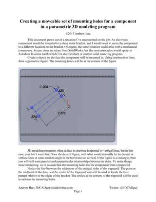
  • 2. Apply dimensions as desired to orient and locate the hole pattern: The zero-degree angular dimension is struck between the central construction line and the edge of the bracket. Extrude the holes from the sketch: Andrew Buc: 3DCADguy@andrewbuc.com Twitter: @3DCADguy Page 2
  • 3. In the assembly, mate (in Inventor, constrain) the electronic component to the mounting bracket. If the hole patterns in the bracket and the component are identical (and they should be), then it will be enough to apply appropriate mates to 2 holes in the bracket and 2 corresponding holes in the component: Now, imagine that the electrical designer wants to move the component and rotate it 90 degrees. Change the dimensions in the sketch accordingly: Andrew Buc: 3DCADguy@andrewbuc.com Twitter: @3DCADguy Page 3
  • 4. Close the sketch and rebuild the bracket and the assembly. Voilà! Andrew Buc: 3DCADguy@andrewbuc.com Twitter: @3DCADguy Page 4