1. A A
BB
3.680
1.197 1.010 1.198
7.522
1.820
0.100
4.978
3.992
0.953 1.500 0.952
1.420
1.108
0.263
BED 3
BED 2
BED 1
BATH
BED 4
EN SUITE
EXT Existing
SVP
RWP
RWP
RWP
Access
hatch
2
2
2
2
2
2
1
1
3
1
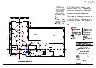
Proposed Side & Rear Extension at 4 Ty-Newydd,
Whitchurch, Cardiff. CF14 1NN
Drawn by Date
M Ferreira 02/2011
Checked by Date
B McCarthy 02/2011
1:50 on A3
Drawing Name
Drawing Scale
Drawing Number: Status Revision
BR/04 of 9
Job Title
Proposed First Floor Plan
BMac Design & Developments
07766 317970 / 02920 310595
3 Bishops Road, Whitchurch, Cardiff. CF14 1LT
Proposed First Floor Plan
For suspended reinforced slabs or beam and block floors to be GEN 1 strip foundations 600mm wide as
above or GEN 1 trench fill 600mm wide to external walls reducing to 450mm wide under internal walls. All
the above to Local Authority approval and to be taken down to loadbearing strata. REFER TO
STRUCTURAL ENGINEERS DRAWINGS FOR RAFT DESIGN.
D.P.C 2000g. textured or embossed polythene minimum 150mm above path level and continuous with
d.p.m (cavity walls to be filled to minimum 225mm below d.p.c with weak mix concrete). 2.no. courses of
engineering bricks to be laid below the d.p.c on the outer leaf of the external wall.
Above ground and rainwater drainage details, including runs, connections and discharging points, are to
be agreed with the Building Control Officer on site.
Where drains pass through walls form openings with proprietary p.c. concrete lintel over with min. 150mm
bearing.
Pipes to have a minimum of 50 mm clearance all around with the void filled with compressible sealant
and openings masked with rigid sheet material. All to be carried out in accordance with BS8301.
EXT - Ceiling Mounted Extract Fan 15l/s
and must be light switch connected and
fitted with a 15 minute overrun.
S Smoke/heat detectors to be interlinked
with battery backup to BS5839.6
An automatic fire alarm & smoke detection
system is required to be installed complying
with BS5839, Part 1:2002
On completion an appropriate installation &
completion certificate must be provided. All
systems to include a heat detector to the
kitchen area.
Radiator positions & sizes to be confirmed
with client.
Downlighters in accordance with clients
specification.
Twin switched socket outlet 450mm affl.
Single 13A switched socket outlet 1050mm
affl (F)= Fused spur at high level.
Twin switched socket outlet 1050mm affl.
External lighting to be agreed with client.
TV
TV aerial.
2
FAF - Fan Assisted Flue.
1 gang 2 way switch 1370 affl.
1 gang 1 way switch 1370 affl.
CHF - Cooker Hood Fan 30 litres per
second ventilation.
VDPC - Vertical Damp Proof Course.
EXT - Extract Fan wall. (F)
Ceiling mounted pull cord.
BIG - Back Inlet Gully
Ceiling mounted fused pull cord.F
SVP - Soil & Vent Pipe.
External water tap.
Where applicable
RWP - Rainwater pipe to be connected to
the existing surface water drainage or
soakaway.
Pendant light.
EXTERNAL WALL CONSTRUCTION Standard (312mm Thickness) 110 Cavity.EXTERNAL WALL CONSTRUCTION Standard (312mm Thickness) 110 Cavity.EXTERNAL WALL CONSTRUCTION Standard (312mm Thickness) 110 Cavity.EXTERNAL WALL CONSTRUCTION Standard (312mm Thickness) 110 Cavity.
(Blockwork above dpc when rendered) 60mm celotex 50mm air cavity to achieve U value of 0.28
w/m2k. 100mm TARMAC HEMELITE 3.5N/mm2 BLOCK INNER SKIN (or 7N/mm2 if specified by
engineer) Leaves of external walls to be tied togther 225mm long Stainless Steel or non ferrous wall
ties to BS 1243: 1978 &BS 5628 at 750mm horizontally & 450mm vertical staggered centres. Wall ties
to be within 225mm horizontally & vertically of all openings or movement joints.
Foundations in aggressive soils or other hazardous conditions obtain special advice. Non standard or
special foundations to be to Structural Engineer's design. Traditional Foundations in non aggressive
soils or other non hazardous conditions. Allowance to be made for deeper footings where necessary
and to be confirmed with building control.
For Ground bearing floors not designed as suspended or reinforced to be strip foundation in GEN 1
(Designed mix) concrete, 600mm wide, 200mm thick with maximum 300mm steps and maximum
600mm concrete laps at steps. Or trench fill in GEN 1 (Designed mix) concrete 450mm wide, top level
to be 300mm below finished floor level.
Scaled dimensions may be used for approximation.
Ensure only figured dimensions are used for
construction. All dimensions to be checked on site.
1 Bond all new internal walls to existing
masonry by indenting every other course.
Bond new external walls to existing masonry
with Crocodile C10 wallplates or similar
approved (above DPC only). Fix with flanges
facing into cavity. Fix plates over Trueline
Crocodile S24 Sealant Strip moisture
barriers and disc cut vertical DPC into
existing leaf.
6 Velux roof window sizes to be agreed
with client and installed as per
manufacturers recommendations.
3 75 x 50mm studwork to be insulated with
Rockwool Flexi finished with 12.5mm
plasterboard and skim.
4 Proposed steel beams on padstones in
accordance with structural engineers
calculations.
2 Cavity wall construction to include
insulation to meet Uvalue of 0.28w/m2k.
Where applicable
5 End of beams to be built into internal skin
of existing wall using decent brick infill and to
receive a good finish. Note: Beam lengths to
be confirmed on site prior to manufacturing.
Depth of existing foundations to be checked
with Building Control Officer if required and
allowance made for additional underpinning
of foundations if required.