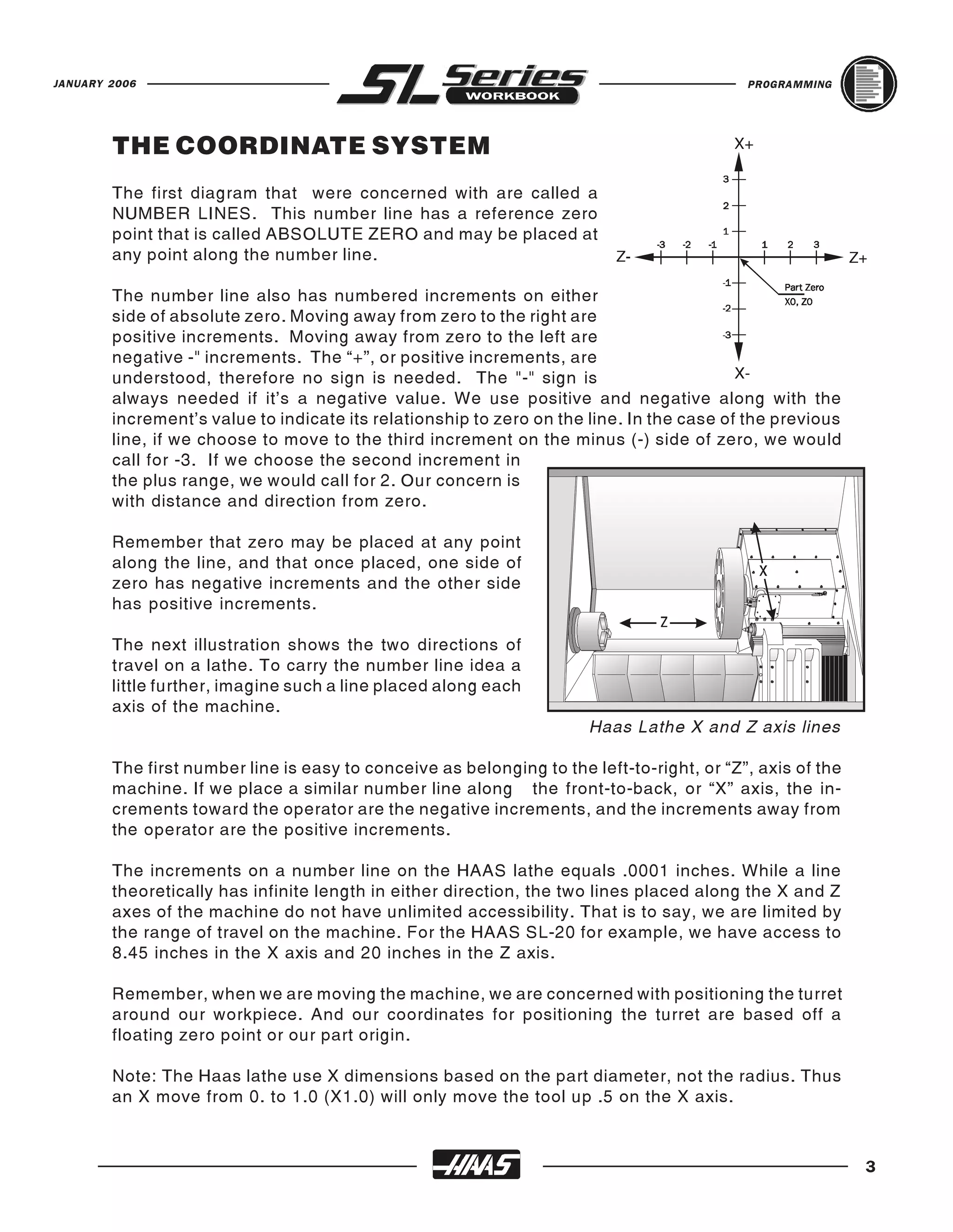
SlideShare a Scribd company logo
1 of 160
Download to read offline
PROGRAMMING WORKBOOK


     HAAS AUTOMATION, INC.
        2800 Sturgis Rd.
        Oxnard, CA 93030


          JANUARY 2006
.
JANUARY 2006                                                                                     PROGRAMMING


                                            HAAS AUTOMATION INC.
                                                2800 Sturgis Road
                                              Oxnard, California 93030
                                               Phone: 805-278-1800
                                               www.HaasCNC.com

        The information in this workbook is reviewed regularly and any necessary changes will be incor-
        porated in the next revision. This material is subject to change without notice.

        Warning: This workbook is for the exclusive use of Haas Customers, Distributors and Trainers
        and is protected by copyright law. The reproduction, transmission or use of this document or its
        contents for profit is not permitted.

        All content is the property of Haas Automation, Inc., copyright 2006. This Workbook may not be
        copied,distributed or reproduced for profit, in full or in part, without written permission from Haas
        Automation, Inc. This training information is being supplied for free to all Haas
        customers and schools that are learning to use Haas equipment. Haas information should never
        be modified unless you have written permission by Haas Automation.

        Enquiries to Haas Automation about training information or a letter of authorization to copy,
        contact ebowman@haascnc.com


                                         Copyright 2006, Haas Automation


                                                                                                                I
PROGRAMMING                                                                                     JANUARY 2006


                     CUSTOMER SATISFACTION PROCEDURE

     Dear Haas customer,

     Your complete satisfaction and goodwill are of the utmost importance to both Haas Automation,
     Inc., and the Haas distributor where you purchased your equipment. Normally, any concerns you
     may have about the sales transaction or the operation of your equipment will be rapidly resolved
     by your distributor.

     However, if your concerns are not resolved to your complete satisfaction, and you have dis-
     cussed your concerns with a member of the dealership’s management, the General Manager or
     the dealership’s owner directly, please do the following:

     Contact Haas Automation’s Customer Service Center by calling 800-331-6746 and ask for the
     Customer Service Department. So that we may resolve your concerns as quickly as possible,
     please have the following information available when you call:

           •   Your name, company name, address and phone number
           •   The machine model and serial number
           •   The dealership name, and the name of your latest contact at the dealership
           •   The nature of your concern

           If you wish to write Haas Automation, please use this address:

           Haas Automation, Inc.
           2800 Sturgis Road
           Oxnard, CA 93030
           Att: Customer Satisfaction Manager
           e-mail: Service@HaasCNC.com

     Once you contact the Haas Automation Customer Service Center, we will make every effort to
     work directly with you and your distributor to quickly resolve your concerns. At Haas Automation,
     we know that a good Customer-Distributor-Manufacturer relationship will help ensure continued
     success for all concerned.

     NOTE: Should you have a problem with your machine, please consult your operator's manual
     first. If this does not resolve the problem, call your authorized Haas distributor. As a final
     solution, call Haas directly at the number indicated below.


                                Haas Automation, Inc.
                                2800 Sturgis Road
                                Oxnard, California 93030-8933                USA
                                Phone: (805) 278-1800


II
JANUARY 2006                                                                                            PROGRAMMING


                                                  CONTENTS
    INTRODUCTION ........................................................................................................ 1
    HAAS LATHE SPECIFICATIONS ..................................................................................... 2
    THE COORDINATE SYSTEM ......................................................................................... 3
    MACHINE HOME ...................................................................................................... 4
    ABSOLUTE AND INCREMENTAL POSITIONING ................................................................... 5
    TYPICAL LATHE PART ................................................................................................ 7
    PROGRAMMING WITH CODES ..................................................................................... 10
    PROGRAM FORMAT ................................................................................................. 11
    DEFINITIONS WITHIN THE FORMAT .............................................................................. 13
    SAFE START UP LINE??? ........................................................................................... 14
    OFTEN USED PREPARATORY "G" CODES ........................................................................ 16
    OFTEN USED PREPARATORY "M" CODES ........................................................................ 17
    PROGRAM STRUCTURE ............................................................................................ 18
    MISCELLANEOUS FUNCTIONS "M" CODES ...................................................................... 20
    PREPARATORY FUNCTIONS "G" CODES ......................................................................... 22
    MACHINE DEFAULTS ................................................................................................ 25
    MACHINE CYCLES FOR THE LATHE ............................................................................... 26
    ALPHABETICAL ADDRESS CODES ................................................................................ 28
    RAPID POSITION COMMAND (G00) .............................................................................. 31
    LINEAR INTERPOLATION COMMAND (G01) ..................................................................... 32
    LINEAR INTERPOLATION EXERCISE.............................................................................. 33
    CIRCULAR INTERPOLATION COMMANDS (G02 G03) .......................................................... 34
    CIRCULAR INTERPOLATION EXERCISES ......................................................................... 38
    CHAMFERING AND CORNER ROUNDING WITH G01 ........................................................... 41
    CHAMFERING AND CORNER ROUNDING WITH G01 EXERCISE .............................................. 45
    MISCELLANEOUS G CODES (G04) ................................................................................ 46
    INCH / METRIC SELECTION (G20, G21) .......................................................................... 46
    REFERENCE POINT RETURN COMMANDS (G28 G51) ......................................................... 47
    SPINDLE SPEED COMMANDS (G50, G96, G97) ................................................................ 48
    WORD COORDINATE SYSTEM COMMANDS (G52 G53 G54-G59 G110-G129) ............................. 49
    FEED COMMANDS (G98 G99) ...................................................................................... 50

                                                                                                                          III
PROGRAMMING                                                                                             JANUARY 2006


                                              CONTENTS
 MANUALLY PROGRAMMING TNC FOR A RADIUS .............................................................. 50
 MANUALLY PROGRAMMING TNC FOR AN ANGLE ............................................................. 53
 TOOL NOSE COMPENSATION (G40, G41, G42) ................................................................. 56
 TOOL TIP DIRECTION DIRECTION CHARTS ...................................................................... 68
 EXAMPLE PROGRAM USING TOOL NOSE COMPENSATION ................................................... 74
 MACHINE CYCLES FOR TURNING AND GROOVING ............................................................ 78
 O.D. AND I.D. STOCK REMOVAL CYCLE (G71) ................................................................. 79
 TYPE I ROUGHING MACHINING DETAILS (G71) ................................................................. 81
 FINISHING CYCLE (G70) ............................................................................................ 83
 G71/G70 TYPE I ROUGHING & FINISHING AN O.D. WITH TNC EXERCISE .................................. 86
 G71/G70 TYPE I ROUGHING & FINISHING AN I.D. WITH TNC EXAMPLE .................................... 88
 TYPE II ROUGH MACHINING DETAILS (G71)..................................................................... 89
 TYPE II ROUGHING EXAMPLE (G71) .............................................................................. 90
 71/G70 TYPE II ROUGHING & FINISHING AN O.D. WITH TNC EXERCISE ................................... 92
 END FACE STOCK REMOVAL CYCLE (G72) ....................................................................... 94
 TYPE I ROUGHING MACHINING DETAILS (G72) ................................................................. 95
 G72/G70 TYPE I ROUGHING & FINISHING A FACE WITH TNC EXERCISE .................................... 98
 IRREGULAR PATH STOCK REMOVAL CYCLE (G73) ............................................................ 100
 G73/G70 TYPE I IRREGULAR STOCK REMOVAL & FINISHING AN O.D. WITH TNC EXERCISE .......... 102
 END FACE GROOVING CYCLE OR HIGH SPEED PECK DRILLING (G74) ..................................... 104
 G74 SINGLE PASS PROGRAM EXAMPLE ....................................................................... 105
 G74 MULTIPLE PASS PROGRAM EXAMPLE .................................................................... 106
 G74 HIGH SPEED PECK DRILLING EXAMPLE ................................................................... 107
 O.D. / I.D. GROOVING CYCLE (G75) ............................................................................. 108
 G75 SINGLE PASS PROGRAM EXAMPLE ....................................................................... 109
 G75 MULTIPLE PASS PROGRAM EXAMPLE .................................................................... 110
 MULTIIPLE PASS THREAD CUTTING CYCLE (G76) ............................................................. 111
 G76 MULTIIPLE PASS THREAD CUTTING CYCLE EXAMPLE .................................................. 113
 THREAD CHARTS ................................................................................................... 115
 G76 O.D. THREADING EXERCISE ................................................................................ 117
 DRILLING BORING AND TAPPING CANNED CYCLES .......................................................... 118

IV
JANUARY 2006                                                                                        PROGRAMMING


                                                CONTENTS
    CANCEL CANNED CYCLE (G80) ................................................................................... 119
    DRILL CANNED CYCLE (G81) ..................................................................................... 119
    SPOT DRILL/COUNTERBORE CANNED CYCLE (G82) .......................................................... 120
    DEEP HOLE PECK DRILLING CANNED CYCLE (G83)........................................................... 121
    TAPPING CANNED CYCLE (G84) .................................................................................. 123
    REVERSE TAPPING CANNED CYCLE (G184) .................................................................... 124
    BORE IN BORE OUT CANNED CYCLE (G85) ..................................................................... 125
    BORE IN STOP RAPID OUT CANNED CYCLE (G86) ............................................................ 126
    BORE IN MANUAL RETRACT CANNED CYCLE (G87) .......................................................... 127
    BORE IN DWELL MANUAL RETRACT - CANNED CYCLE (G88) ............................................... 128
    BORE IN DWELL BORE OUT CANNED CYCLE (G89) ........................................................... 129
    O.D./I.D. TURNING CYCLE MODAL (G90) ....................................................................... 130
    G90 MODAL TURNING CYCLE WITH TNC EXAMPLE ........................................................... 131
    THREAD CUTTING CYCLE MODAL (G92) ........................................................................ 132
    END FACE TURNING CYCLE MODAL (G94) ..................................................................... 134
    G94 MODAL TURNING CYCLE WITH TNC EXAMPLE ........................................................... 135
    MISCELLANEOUS CODES SUMMARY (M CODES) ............................................................. 136
    M CODE DETAILED DESCRIPTION ................................................................................ 138


                                                                                                                     V
PROGRAMMING   JANUARY 2006


VI
JANUARY 2006                                                                          PROGRAMMING


        INTRODUCTION
        This workbook provides basic programming principles necessary to begin programming
        the HAAS C.N.C. Lathe.

        In a “CNC” (Computerized Numerical Control) machine, the tool is controlled by a
        computer and is programmed with a machine code system that enables it to be operated
        with minimal supervision and with a great deal of repeatability.

        The same principles used in operating a manual machine are used in programming a CNC
        machine. The main difference is that instead of cranking handles to position a slide to a
        certain point, the dimension is stored in the memory of the machine control once. The
        control will then move the machine to these positions each time the program is run.

        In order to operate and program a CNC controlled machine, a basic understanding of
        machining practices and a working knowledge of math is necessary. It is also important
        to become familiar with the control console and the placement of the keys, switches,
        displays, etc., that are pertinent to the operation of the machine.

        This Haas lathe workbook can be used for both operator’s and programmer’s. It is meant
        as a supplementary teaching aid for the user of HAAS Lathes. The information in this
        workbook may apply in whole or in part to the programming of other CNC machines. It is
        intended to give a basic understanding of CNC programming and it’s applications. It is not
        intended as an in-depth study of all ranges of the machine use, but as an overview of
        common and potential situations facing CNC programmers. Much more training and
        information is necessary before attempting to program on the machine. For a complete
        explanation and an in-depth description, refer to the Programming and Operation Manual
        that is supplied with your HAAS lathe.


                                                                                                     1
PROGRAMMING                                                                                                  JANUARY 2006


             HAAS LATHE MACHINE SPECIFICATIONS
                             MINI          SL-10        SL-20        TL-15*       SL-30        TL-25*       SL-40

CAPACITY
Chuck Size            5C Collet             6.5"         8.3"         8.3"        10.0"         10.0"       15.0"
Standard Bar Capacity   1.06"               1.75"        2.0"         2.0"        3.0"          3.0"        4.0"
Between Centers         N/A                 16.5"        24.0"        12.7"       39.0"         39.0"       51.0"
Max. Cutting Dia.                           11.0"        10.3"        8.2"        17.0"         16.0"       25.5"
Max. Cutting Length                         14.0"        20.0"        17.5"       34.0"         34.0"       44.0"

SPINDLE
Peak Horsepower               7.5Hp         15Hp         20Hp         20Hp        30Hp          30Hp        40Hp
Max. RPM                      6,000 rpm     6,000 rpm    4,000 rpm    4,000 rpm   3,400 rpm     3,400 rpm   2,400 rpm
Spindle Nose                  A2-5          A2-5         A2-6         A2-6        A2-6          A2-6        A2-8
Spindle Bore Dia.             1.38"         2.31"        3.00"        3.00"       3.50"         3.50"       4.62"
Draw Tube Bore Dia.           1.18"         1.81"        2.06"        2.06"       3.03"         3.03"       4.06"

SWING DIAMETER
Over front apron                            16.25"       23.0"        20.0"       30.0"         30.0"       40.0"
Over cross slide              5.8"          8.0"         9.5"         9.5"        14.5"         14.5"       25.0"

TRAVELS
X-Axis                        12.0"         6.25"        8.45"        7.5"        11.3"         11.3"       17.0"
Z-Axis                        12.0"         14.0”        20.0"        17.5”       34.0"         23.0"       44.0"

FEED RATES
Axis Motor’s Max. Thrust 2000 Ibs.          3400 Ibs.    3400 Ibs.    3400 Ibs.     SL-30, 25, 40 X=3400 Ibs. Z=5400 Ibs.
                                                                                  For
Rapid - AC Brushless     600 ipm            710 ipm      710 ipm      710 ipm     710 ipm     710 ipm     710 ipm

TOOLS                         Gang style    Turret       Turret       Turret      Turret        Turret      Turret
Number Of Tools               up to 10      12            10          12          12            12          10

MISCELLANEOUS
Coolant (U.S. Gallons)        24            15           40           40          50            50          77

TAILSTOCK
Taper                         N/A           MT3          MT4          N/A         MT4           N/A         MT5
Travel                        N/A           4.0"         20"          N/A         33.5"         N/A         44"
Thrust                        N/A     225-900 Ibs . 300-1500 Ibs.     N/A      300-1500 Ibs.    N/A      300-1500 Ibs.

    * Live   Tooling Lathe


2
JANUARY 2006                                                                               PROGRAMMING


        THE COORDINATE SYSTEM
        The first diagram that were concerned with are called a
        NUMBER LINES. This number line has a reference zero
        point that is called ABSOLUTE ZERO and may be placed at
        any point along the number line.

        The number line also has numbered increments on either
        side of absolute zero. Moving away from zero to the right are
        positive increments. Moving away from zero to the left are
        negative -" increments. The “+”, or positive increments, are
        understood, therefore no sign is needed. The "-" sign is
        always needed if it's a negative value. We use positive and negative along with the
        increment’s value to indicate its relationship to zero on the line. In the case of the previous
        line, if we choose to move to the third increment on the minus (-) side of zero, we would
        call for -3. If we choose the second increment in
        the plus range, we would call for 2. Our concern is
        with distance and direction from zero.

        Remember that zero may be placed at any point
        along the line, and that once placed, one side of
        zero has negative increments and the other side
        has positive increments.

        The next illustration shows the two directions of
        travel on a lathe. To carry the number line idea a
        little further, imagine such a line placed along each
        axis of the machine.
                                                                      Haas Lathe X and Z axis lines

        The first number line is easy to conceive as belonging to the left-to-right, or “Z”, axis of the
        machine. If we place a similar number line along the front-to-back, or “X” axis, the in-
        crements toward the operator are the negative increments, and the increments away from
        the operator are the positive increments.

        The increments on a number line on the HAAS lathe equals .0001 inches. While a line
        theoretically has infinite length in either direction, the two lines placed along the X and Z
        axes of the machine do not have unlimited accessibility. That is to say, we are limited by
        the range of travel on the machine. For the HAAS SL-20 for example, we have access to
        8.45 inches in the X axis and 20 inches in the Z axis.

        Remember, when we are moving the machine, we are concerned with positioning the turret
        around our workpiece. And our coordinates for positioning the turret are based off a
        floating zero point or our part origin.

        Note: The Haas lathe use X dimensions based on the part diameter, not the radius. Thus
        an X move from 0. to 1.0 (X1.0) will only move the tool up .5 on the X axis.


                                                                                                           3
PROGRAMMING                                                                               JANUARY 2006


    The zero position may be placed at any point along each of the two number lines, and in
    fact will probably be different for each setup of the machine. It is noteworthy to mention
    here that the X-axis is usually set with the machine zero position on the center line of the
    spindle, while the Z axis zero is usually set at the finished right end surface of the part
    being machined. This places all X axis cutting in a positive range of travel, whereas the Z
                                    axis cutting would be in the negative range of travel.

                                   The diagram at left shows a front view of the grid as it would
                                   appear on the lathe. This view shows the X and Z axes as
                                   the operator faces the lathe. Note that at the intersection of
                                   the two lines, a common zero point is established. The four
                                   areas to the sides and above and below the lines are called
                                   “QUADRANTS” and make up the basis for what is known
                                   as rectangular coordinate programming.

                                   QUADRANT       1   is   on   the   Top Right at X+, Z+
                                   QUADRANT       2   is   on   the   Top Left at X+, Z-
                                   QUADRANT       3   is   on   the   Bottom Left at X-, Z-
                                   QUADRANT       4   is   on   the   Bottom Right at X-, Z+

                                  Whenever we set a zero somewhere on the X axis and
                                  somewhere on the Z axis, we have automatically caused an
                                  intersection of the two lines. This intersection where the two
    zeros come together will automatically have the four quadrants to its sides, above, and
    below it. How much of each quadrant that is accessible is determined by where we place
    the zeros on the travel axes of the lathe.

    For example, if we set zero exactly in the middle of the Z axis and if we set the X axis zero
    on the spindle center line, we have created four quadrants. For an SL-20 for example, the
    upper two quadrants of the Z travel is 10 inches and the X travel is 7.45 inches. The lower
    two quadrants will have Z travel of 10 inches and X travel of 1 inch. The HAAS lathes have
    1 inch of negative travel beyond the center line of the spindle.

    MACHINE HOME
    The principal of machine home may be seen when doing a reference return of all machine
    axes at machine startup. A zero return (POWER UP/RESTART) is performed when you
    power on machine. All axes will then move to the furthest positive locations, to the upper
    right of machine, until the limit switches are reached. When this condition is satisfied, the
    only way to move any of the axes is in the negative direction. This is because the machine
    zero, is set to the furthest positive point to the upper right of the machine, when the
    machine was sent Home with a POWER UP/RESTART.

    Machine Home is placed at the edge of each axes travel. In effect, now the positive
    quadrants cannot be reached, and all the X and Z moves will be found to be in the X-, Z-
    quadrant. It is only by setting a new location with, Tool Geometry and Work Zero Offsets
    somewhere within the travel of each axis that other quadrants are able to be reached.


4
JANUARY 2006                                                                                 PROGRAMMING


                                   X+


                Z-                                           Z+


                                   X-
        It “would not” be convenient to program our parts from the machine zero, so secondary
        floating zero point is established with offsets. This floating zero is referred to by either,
        PART ZERO or PART ORIGIN, both having the same meaning.

        To create the new part zero location, each tool is manually touched off of the part being
        setup, on the diameter and the length. Then through a series of control key strokes, that
        distance from machine zero to the part zero is stored for X & Z axes, in tool offsets, and
        activated later, from the part program, when that tool is used for cutting a part.

        Centerline of the lathe spindle will always be "X" zero and the "Z” zero location will "float"
        to the face on the part that reflects most of the part length dimensions. Normally the front
        face is used, because it’s usually easier to access for touch-off procedure and also easier
        to program.

        ABSOLUTE AND INCREMENTAL POSITIONING
        Up to this point, we have defined a system of positioning the tool that is known as absolute
        programming. In absolute, all coordinate points are given, in X and Z axis, with regard to their
        relationship to a fixed part zero or an origin point. This is the most common type of positioning.

        Another type of positioning is called incremental. Incremental positioning is defined using
        U and W. The "U" character is used to specify incremental motion in the X-axis, and the
        "W" character is used to specify incremental motion in the Z axis. Both “U” and “W” define
        distance and direction from a point to point location. An incremental coordinate position is
        entered, using U and W, in terms of its relationship to the previous position, and not from
        a part zero or part origin point. In other words, after a block of information has been
        executed, the position that the tool is now at is the new zero point for the next move to be
        made. The "U" address is used to specify an incremental move along the "X" axis and the
        "W" address is used to specify an incremental move along the "Z" axis.


                                                                                                             5
PROGRAMMING                                                                            JANUARY 2006


    An example of the use of the incremental system is shown below. Note that to move from
    Z-3.375 to Z-.625 on the scale, a positive incremental move of W2.750 was made, even
    though the move W still places the tool on the minus side of the Z scale. Therefore the move
    was determined from the start point position, with no regard for the fixed zero reference
    point. The + and - signs are used in terms of direction from the starting point, and are not
    defined in regard to the part zero point.


                              An example of an incremental move.

    Keep in mind that when positioning in absolute, we are concerned with distance and
    direction from a fixed part zero reference point, and when positioning in incremental we
    are concerned with distance and direction from the last point.

    Absolute mode should be your positioning mode of choice for most applications. There are
    times when incremental mode can be quite helpful. Repeating motions within a subroutine,
    for example, is one excellent example. If you have six identical grooves to turn on a Haas
    lathe, you can save programming effort if you specify the motions incrementally to
    machine one groove. Then just call up the subroutine again to repeat the commands to do
    another groove at a new location.

    There are even times when it is helpful to command one axis move in the absolute mode
    while another moves in incremental mode. Any turning center using U and W to specify
    incremental motions in X and Z easily allows this. Say you’re experiencing some unwanted
    taper on a diameter and you want to program a tapering movement to counteract the
    problem. In the command that turns the diameter that is experiencing unwanted taper, you
    can specify the Z endpoint in absolute mode from program zero and the X endpoint as an
    incremental move. Here is an example:

                                   N040 G01 U0.002 Z-2.5 F0.005

    In this command, the tool will move 0.002 inch, on the diameter, in the X positive direction
    while the Z axis moves to an endpoint of minus 2.5 inches relative to program zero.

    Note: The Haas lathe used absolute X dimensions based on the part diameter, not the
    radius. Thus an X move from 0. to 1.0 (X1.0) will only move the tool up .5 on the X axis.
    Like X axis absolute moves, incremental U movements are specified for the part diameter,
    not the radius. Thus a U move from 0. to 1.0 (U1.0) will only move the tool up .5
    incrementally on the X axis.


6
JANUARY 2006                                                                            PROGRAMMING


        TYPICAL LATHE PART
        We can now take this part and show it in a TYPICAL LATHE SETUP, This would include
        showing the part, soft jaws, and chuck. Starting with this drawing, you will see this symbol

               shown on the parts, this target is to indicate where the FLOATING ZERO has been
        established by the programmer.


                                                                                                       7
PROGRAMMING                                                                         JANUARY 2006


    We can now take our TYPICAL LATHE PART and record the geometry points needed to
    program this part. Diameters are defined as the actual diameter value and not the radius
    from center.


                                            X                        Z
    Values for the Points are :


                                  (Diameter not Radius)

              Point 1             ______________             ______________

              Point 2             ______________             ______________

              Point 3             ______________             ______________

              Point 4             ______________             ______________

              Point 5             ______________             ______________

8
JANUARY 2006                                                                       PROGRAMMING


        Calculate and record the X-axis diameters and Z-axis lengths for the part shown below.
        The values between (parenthesis) would be points where the tool is already located, and
        those points in a program, would not need to be defined again.


                                                         Pt 1     ________          ________
                                                                     X                  Z


                                                         Pt 2     ________          ( _______ )
                                                         Pt 3     ________          ________
                                                         Pt 4     ( _______ )       ________
                                                         Pt 5     ________          ________
                                                         Pt 6     ________          ________
                                                         Pt 7     ( _______ )       ________
                                                         Pt 8     ________          ( _______ )
                                                         Pt 9     ( _______ )       ________
                                                         Pt 10 _ _ _ _ _ _ _ _      ( _______ )
                                                         Pt 11 ( _______ )          ________
                                                         Pt 12 _ _ _ _ _ _ _ _      ________


                                                                                                  9
PROGRAMMING                                                                             JANUARY 2006


     PROGRAMMING WITH CODES
     The definition of a part program for any CNC consists of movements of the tool and speed
     changes to the spindle RPM. It also contains auxiliary command functions such as tool
     changes, coolant on or off commands, or external M code commands.

     Tool movements consist of rapid positioning commands, straight line moves or movement
     along an arc of the tool at a controlled speed.

     The Haas lathe has two (2) linear axes defined as X axis and Z axis. The X axis moves the
     tool turret toward and away from the spindle center line, while the Z axis moves the tool
     turret along the spindle axis. The machine zero position is where the tool is at the upper
     right corner of the work cell farthest away from the spindle axis. Motion in the X axis will
     move the turret toward the spindle centerline with negative values and away from spindle
     center with positive values. Motion in the Z axis will move the tool toward the spindle chuck
     with negative values and away from the chuck with positive values.

     A program is written as a set of instructions given in the order they are to be performed.
     The instructions, if given in English, might look like this:

           LINE     #1   =   SELECT CUTTING TOOL.
           LINE     #2   =   TURN SPINDLE ON AND SELECT THE RPM.
           LINE     #3   =   RAPID TO THE STARTING POSITION OF THE PART.
           LINE     #4   =   TURN COOLANT ON.
           LINE     #5   =   CHOOSE PROPER FEED RATE AND MAKE THE CUT(S).
           LINE     #6   =   TURN THE SPINDLE AND COOLANT OFF.
           LINE     #7   =   RETURN TO CLEARANCE POSITION TO SELECT ANOTHER TOOL.

     and so on. But our machine control understands only these messages when given in
     machine code, also referred to as G and M code programming. Before considering the
     meaning and the use of codes, it is helpful to lay down a few guidelines.


10
JANUARY 2006                                                                                    PROGRAMMING


        PROGRAM FORMAT
        There is no positional requirement for the address codes. They may be placed in any order
        within the block. Each individual can format their programs many different ways. But,
        Program format or program style is an important part of CNC machining. There are some
        program command formats that can be moved around, and some commands need to be a
        certain way, and there are some standard program rules that are just good to follow. The
        point is that a programmer needs to have an organized program format that’s consistent
        and efficient so that any CNC machinist in your shop can understand it.

        Some standard program rules to consider are:

        Program X and Z in alphabetical order on any block. The machine will read Z or X in any
        order, but we want to be consistent. If both X and Z are on a command line in a program,
        they should be listed together and in order. Write X first, and Z second.

        You can put G and M codes anywhere on a line of code. But, in the beginning when N/C
        programming was being developed G codes had to be in the beginning of a program line
        and M codes had to be at the end. And this rule, a lot of people still follow and is a good
        standard to continue.

        Some CNC machines allow you to write more the one M code per line of code and some
        won’t. On the HAAS, only one M code may be programmed per block and all M codes are
        activated or cause an action to occur after everything else on the line has been executed.

        Program format is a series and sequence of commands that a machine may accept and
        execute. Program format is the order in which the machine code is listed in a program that
        consist of command words. Command words begin with a single letter and then numbers for
        each word. If it has a plus (+) value, no sign is needed. If it has a minus value, it must be entered
        with a minus (-) sign. If a command word is only a number and not a value, then no sign or
        decimal point is entered with that command. Program format defines the "language of the
        machine tool."      ...
              ...
              G82 Z-0.2 P0.3 R0.1 F0.003
              G80 G00 Z1. M09
              G28
              MO1

               N4 (Drill .312 Dia. x 1.5 Depth)
               G28
               T404 (5/16 DIA. DRILL)
               G97 S2400 M03
               G54 G00 X0. Z1. M08
               G83 Z-1.5 Q0.3 R0.1 F0.006
               G80 G00 Z1. M09
               G28
               MO1
               ...

                                                                                                                11
               ...
PROGRAMMING                                                                         JANUARY 2006


     AN EXAMPLE OF THE PROGRAM'S FIRST COUPLE OF LINES:
     THE FIRST LINE or block of a program, should be a return to machine zero (using G28 or
     G51 codes). Any tool change should be after a return to machine zero or a tool change
     location. Although this is not necessary it is a good safety measure.

     THE SECOND LINE of code should apply to any appropriate tool selections and tool
     geometry offsets or tool shifts.

     THE THIRD LINE may optionally contain a spindle speed maximum for the tool being used.

     THE FOURTH LINE or block should cancel any constant surface speed mode (G97). And
     it should specify a constant spindle speed command (S____) along with a spindle ON
     clockwise command (M03).

     THE FIFTH LINE should contain a work offset (G54), a preparatory code (G00) for
     rapid command with an X and Z location for positioning the turret, and turn on the
     coolant (M08).

     THE SIXTH LINE may choose to, optionally specify a Constant Surface Speed with (G96)
     and a surface feet per minute (SFM) defined with a (S____) command .

     An example of the program’s startup lines might look like this:

     With Constant
     Surface Speed

     N11   G28 ;
     N12   T101 (O.D. TOOL x .031 TNR);
     N13   G50 S2800 ;
     N14   G97 S650 M03 ;
     N15   G54 G00 X1.85 Z1. M08;
     N16   G96 S315 ;

     Without Constant
     Surface Speed

     N21   G28 ;
     N22   T101 (.750 DIA. DRILL);
     N23   G97 S1600 M03 ;
     N24   G54 G00 X0. Z1. M08;

      All the necessary codes for each operation are listed in the following pages. This tool
     startup format is a good example and defines a commonly used program style.


12
JANUARY 2006                                                                              PROGRAMMING


        DEFINITIONS WITHIN THE FORMAT
        1. CHARACTER : A single alphanumeric character value or the "+" and "-" sign.

        2. WORD : A series of characters defining a single function such as, G codes, M codes,
        an "X" axis moves, or "F" feedrate. A letter is the first character of a word for each of the
        different commands. There may be a distance and direction defined for a word in a
        program. The distance and direction in a word is made up of a value, with a plus (+) or
        minus (-) sign. A plus (+) value is recognized if no sign is given in a word.

        3. BLOCK : Series of words defining a single instruction. An instruction may consist of
        a single linear motion, a circular motion or canned cycle, plus additional information such
        as a feedrate or miscellaneous command (M-codes).

        4. POSITIVE SIGNS : If the value following an address letter command such as A, B, C,
        I, J, K, R, U, V, W, X, Y, Z, is positive, the plus sign need not be programmed in.
        If it has a minus value it must be programmed in with a minus (-) sign.

        5. LEADING ZERO'S : If the digits proceeding a number are zero, they need not be
        programmed in. The HAAS control will automatically enter in the leading zero's.
                   EXAMPLE: G0 for G00 and M1 for M01,
        Trailing zeros must be programmed: M30 not M3, G70 not G7.

        6. MODAL COMMANDS : Codes that are active for more than the line in which they are
        issued are called MODAL commands. Rapid traverse, feedrate moves, and canned
        cycles are all examples of modal commands. A NON-MODAL command which once
        called, are effective only in the calling block, and then immediately forgotten by the control.

        7. PREPARATORY FUNCTIONS : "G" codes use the information contained on the line
        to make the machine tool do specific operations, such as :
             1.) Move the tool at rapid traverse.
             2.) Move the tool at a feedrate along a straight line.
             3.) Move the tool along an arc at a feedrate in a clockwise direction.
             4.) Move the tool along an arc at a feedrate in a counterclockwise direction.
             5.) Move the tool thru a series of repetitive operations controlled by "fixed
                 cycles" such as, spot drilling, drilling, boring, and tapping.

        8. MISCELLANEOUS FUNCTIONS : "M" codes are effective or cause an action to occur
        at the end of the block, and only one M code is allowed in each block of a program.

        9. SEQUENCE NUMBERS : N1 thru N99999 in a program are only used to locate and
        identify a line or block and its relative position within a CNC program. A program can be
        with or without SEQUENCE NUMBERS. The only function of SEQUENCE NUMBERS is
        to locate a certain block or line within a CNC program.

        The machining cycles G70, G71, G72 and G73 require the use of sequence numbers to
        call up specified blocks in a program that in it define the part geometry to rough and finish.


                                                                                                          13
PROGRAMMING                                                                               JANUARY 2006


     SAFE STARTUP LINE???
     G18 G20 G40 G54 G80 G97 G99

     Do you need a safe startup line to be sure all the commands are canceled before starting
     a program? Many programs have a G code default line (or the CAD/CAM programming
     system may output a default line) at the beginning. To be sure machine control is in a safe
     start condition. Here are the conditions on a Haas control, to help you decide if you need
     a safe start line at the beginning of a program.

     G18 Circular Motion ZX Plane Selection - The G18 is the default condition on a Haas
     lathe, and is the only one available in the X and Z axis to do an arc. If you try an arc in the
     G17 XY plane, or the G19 YZ plane, the machine would stop and give you an alarm. There
     is no need to program a G18, it is already active when you power up.

     G20 Inch / G21 Metric Diiensioning - The G codes G20 and G21 are used to select
     between inch and metric. On the HAAS control, the G20 (inch) and G21 (mm) codes are
     used to make sure the inch/metric setting (Setting 9) is set correctly for that program.

     If you’re not switching between inch and metric very much, then why keep putting in these
     G-codes at the start of every program?
     If you did have the wrong condition in Setting 9, graphics display will display whatever
     Setting 9 is set at. You’ll easily see the error when running a program in graphics.

     G54 Work Offset Command - Work offsets on a CNC lathe, are not used like they are on
     a CNC mill. Many lathe users don’t even have values in their work offsets, because all the
     offsets that are needed on a lathe, for most users, are entered in the Tool Geometery
     display. The only time someone might use a work offset on a lathe, is to shift all the tools
     in Z axis the same distance.

     Example: Lets say you want to move all your tools -.015 in the Z axis, to make the parts
     that much shorter. Instead of changing all the tool offsets. You could shift all the tools in
     -0.015 by changing the work offset. Just be sure to take this offset shift out when
     you’re done using it.

                WORK ZERO OFFSET
                G CODE               (X)                   (Z)                   (B)
                G   52               0.                     0.                   0.
                G   54               0.                    -0.015                0.
                G   55               0.                     0.                   0.
                     ...
     Another main reason to use a work offset on a lathe, is when you’re touching off your tools
     on a tool probe. The X axis value is usually always good to the center of the spindle using
     the value touched off in the X axis on a tool probe along with the value in Setting 59 or 60.
     The problem is the distance from the edge of the tool probe in the Z axis to the face of the
     part. So compensate for that difference in the Work Zero Offset, that has in it, the extra
     distance from the edge of the tool probe to the face of the part, in the Z axis.


14
JANUARY 2006                                                                             PROGRAMMING


        Be aware that even if you’re not using a work offset command in a program, G54 is still
        active as a default G code. This is why you see G54 is in the program examples of this
        book, as a reminder that this work offset is active wether you program it in or not. If you’re
        never using work offsets, you may choose to leave this G54 command out.

        G40 Cancels Tool Nose Compensation - You may see a G40 in the beginning of every
        program. And some even put it in at the beginning of every tool, to be sure cutter
        compensation is off, before they start a program.

        You should always cancel cutter compensation (G40) when you’re done using it. If you
        forget to cancel cutter compensation on a lathe, and you run a program in graphics, you’ll
        get a 349PROG STOP W/O CANCEL CUTTER COMP alarm. To let you know, that you
        ended a program without canceling cutter compensation. Pressing RESET or POWER
        OFF will also cancel cutter compensation. Because of these conditions that cancel cutter
        compensation, you don’t need to put a G40 at the beginning of every program.

        G80 Cancels Canned Cycles - If you forget to cancel a canned cycle with a G80, RESET,
        G00, G01, M30 and Power Down will also cancel any active canned cycle.

        G97 Constant Non-Varying Spindle Speed - For safety reasons you should program in
        a G97 at the beginning and end of every tool cycle, with a spindle speed.

        G99 Feed Per Revolution - This command changes how the “F” address is interpreted.
        The F command indicates inches per spindle revolution when Setting 9 is set to INCH. If
        Setting 9 is set to METRIC, F indicates millimeters per revolution. G99 and G98 are modal
        commands. G99 is the default command, and the one you’ll usually want. In certain
        situations you may choose G98 for Feed Per Minute, and then switch back to G99. But
        most customers, will already be in G99 and never switch to G98, so there’s usually no
        need to have it in a safe start line. If a mistake is made, using the wrong feed command,
        you’ll easily see it when it happens, when running the program on the machine.
        Example: If you program a feed of F0.005 to feed per revolution, and you accidentally
        program in a G98 (Feed Per Minute), then it would take forever to feed .005 a minute. If you
        programmed F10. for feed per minute (G98), and you were accidentally in Feed Per
        Revolution (G99), and you had the spindle on, lets say at a low speed of S200. The
        calculated feedrate for this would be 2000ipm, which is above the machine maximum feed
        rate. The machine would stop and give you an alarm.

        There might be good reasons why you want a safe start line at the beginning of every
        program, and some programers like having it at the beginning of every tool, as a safety
        precaution. You may have other machines running these same programs that may need
        safe start up lines. But for many, it may not be necessay. Because of these reasons listed
        above. It’s up to the programer to decide if they want safe start up lines in their programs.


                                                                                                         15
PROGRAMMING                                                                            JANUARY 2006


     OFTEN USED PREPARATORY “G” CODES
     G00   Rapid traverse motion; Used for non-cutting moves of the machine in positioning quick
           to a location to be machined, or rapid away after program cuts have been performed.
           Maximum rapid motion (I.P.M.) of a Haas machine will vary on machine model.

     G01   Linear interpolation motion; Used for actual machining and metal removal.
           Governed by a programmed feed rate in inches (or mm) per revolution (G99).
           Maximum feed rate (I.P.M.) of a Haas machine will vary on machine model.
           (Inch Per Minute = R.P.M. x Inch Per Revolution).

     G02   Circular Interpolation - Clockwise.

     G03   Circular Interpolation - Counterclockwise.

     G28   Machine Home (Rapid traverse)

     G40   Tool Nose Compensation CANCEL

     G41   Tool Nose Compensation LEFT of the programmed path

     G42   Tool Nose Compensation RIGHT of the programmed path

     G50   Spindle Speed Maximum RPM limit

     G70   Finishing Cycle

     G71   O.D./I.D. Stock Removal Cycle

     G72   End Face Stock Removal Cycle

     G76   O.D./I.D. Thread Cutting Cycle

     G80   Cancel Canned Cycle

     G81   Drill Canned Cycle

     G82   Spot Drill Canned Cycle

     G83   Peck Drill Canned Cycle

     G84   Tapping Canned Cycle

     G96   Constant Surface Speed On

     G97   Constant Surface Speed Cancel

     G98   Feed Per Minute

     G99   Feed Per Revolution


16
JANUARY 2006                                                                         PROGRAMMING


        OFTEN USED MISCELLANEOUS “M” CODES
        M00    The M00 code is used for a Program Stop command on the machine.
               It stops the spindle, turns off coolant and stops lookahead processing.
               Pressing CYCLE START again will continue the program on the next
               block of the program.

        M01    The M01 code is used for an Optional Program Stop command.
               Pressing the OPT STOP key on the control panel signasl the machine
               to perform a stop command when the control reads an M01 command. It will
               then perform like an M00.

        M03    Starts the Spindle FORWARD. Must have a spindle speed defined.

        M04    Starts the Spindle REVERSE. Must have a spindle speed defined.

        M05    STOPS the Spindle

        M08    Coolant ON command

        M09    Coolant OFF command

        M30    Program End and Reset to the beginning of program.

        M97    Local Subroutine Call

        M98    Subprogram Call

        M99    Subprogram Return (M98) or Subroutine Return (M97), or a Program Loop.

        NOTE: Only one "M" code can be used per line. And the "M" codes will be the last
        command executed in a line, regardless of where it's located in that line.


                                                                                                   17
PROGRAMMING                                                                                    JANUARY 2006


     PROGRAM STRUCTURE
     A CNC part program consists of one or more blocks of commands. When viewing the
     program, a block is the same as a line of text. Blocks shown on the CRT are always
     terminated by the “;” symbol which is called an EOB (End Of Block). Blocks are made up
     of alphabetical address codes which are always an alphabetical character followed by a
     numeric value. For instance, the specification to move the X-axis would be a number
     proceeded by the X symbol.

     Programs must begin and end with a percent (%) sign. After the first percent (%) sign with
     nothing else on that line, the next line in a program must have a program number beginning
     with the letter O (not zero) and then the number that defines that program. Those program
     numbers are used to identify and select a main program to be run, or as a subprogram
     called up by the main program. The % sign will "not" be seen on the control. But they must
     be in the program when you load a program into the control. And they will be seen when
     you download a program from the machine. The % signs are automatically entered in for
     you, if you enter a program in on the HAAS control.

     A program may also contain a “ / “ symbol. The “ / “ symbol, sometimes called a slash, is
     used to define an optional block. If a block contains this symbol, any information that
     follows the slash in a program block, will be ignored when the BLOCK DELETE button is
     selected when running a program.

     On the following page is a sample program as it would appear on the CRT. The words
     following the “:” are not part of the actual program but are put there as further explanation.

     This program will rough and finish turn and face for a part with two diameters along with
     drilling and tapping for a 3/8-16 x 1.0 deep threaded hole one end.

     %                                      :Program must begin and end with a %
     O00018 ;                               :Letter “O” and a five digit program number
     (CNC LATHE PROGRAM EXAMPLE) ;          :Comment statement between parenthesis
     N1 (Rough O.D.) ;                      :First operation
     G28 ;                                  :Return to machine zero for a tool change, cancel tool offset
     T101 (O.D. TOOL x .031 TNR) ;          :Select tool 1 with offset 1
     G50 S2600 ;                            :Set spindle speed max. clamp 2600 RPM
     G97 S414 M03 ;                         :Cancel CSS, 415 spindle speed, on forward
     G54 G00 X3.6 Z0.1 MO8 ;                :Work offset, rapid X, Z axes, coolant on
     G96 S390 ;                             :CSS on at 390 SFM, coolant on
     G00 Z0.005 ;                           :Rapid to .005 from the end of part
     G01 X-0.063 F0.005 ;                   :Rough face end of part
     G00 X3.6 Z0.1 ;                        :Rapid to start point above part
     G71 P10 Q20 U0.01 W0.005 D0.1 F0.01    ;:Rough turning G71 canned cycle using the path defined
                                            :between N10 thru N20, leaving .010 stock on the X-axis
                                            :diameters, .005 stock on the linear faces, with 0.1 depth
                                            :of cut each pass, feeding .010 per revolution.
     N10 G42 G00 X0.82 ;                    :N10 is the starting block called by the P block in the G71
     G01 Z0. F0.004 ;                       :line that difines in it the geometery to rough out.

18
JANUARY 2006                                                                               PROGRAMMING


        X0.9 ;                             :Lines that defines the part geometery to rough out
        G03 X1. Z-0.05 R0.05 ;                 “       “       “       “      “      “
        / G01 Z-1.75 ;                         “       “       “       “      “      “
        / X1.75 ;                              “       “       “       “      “      “
        / G03 X2.25 Z-2. R.25 ;                “       “       “       “      “      “
        G01 Z-3.25 F0.004 ;                    “       “       “       “      “      “
        X2.94 ;                                “       “       “       “      “      “
        X3. Z-3.28 ;                           “       “       “       “      “      “
        Z-4.1 ;                                “       “       “       “      “      “
        N20 G40 X3.6 ;                     :End of geometery with Q20 in G71 line, cancel cutter comp.
        G97 S414 M09 ;                     :Cancel CSS, coolant off
        G28 ;                              :Return to machine zero for a tool change, cancel tool offset
        MO1 ;                              :Optional program stop
        ;
        N2 (FINISH O.D.) ;                 :Second operation
        G28 ;                              :Return to machine zero for a tool change, cancel tool offset
        T202 (O.D. TOOL x .031 TNR) ;      :Select tool 2 with offset 2
        G50 S2600 ;                        :Spindle speed max. of 2600 RPM
        G97 S1354 M03 ;                    :Cancel CSS, 1350 spindle speed, on forward
        G54 G00 X1.1 Z0.1 M08 ;            :Work offset, rapid X and Z axis, coolant on
        G96 S390 ;                         :CSS on at 390 SFM
        G00 Z0. ;                          :Rapid to end of part
        G01 X-0.032 F.003 ;                :Finish face end of part
        G00 X3.6 Z0.1 ;                    :Rapid to start point above part
        G70 P10 Q20 ;                      :Finishing cycle calling N10thru N20 to do a finish pass
        G97 S414 ;                         :Cancel CSS, 475 spindle speed
        G00 Z1.0 M09 ;                     :Rapid Z axis, coolant off
        G28 ;                              :Return to machine zero for a tool change, cancel tool offset
        M01 ;                              :Optional program stop
        ;
        N3 (Drill .750 Dia. x 2.5 Depth) ; :Third operation
        G28 ;                              :Return to machine zero for a tool change, cancel tool offset
        T303 (3/4 DIA. DRILL) ;            :Select tool 3 with offset 3
        G97 S1986 M03 ;                    :Cancel CSS, 1950 spindle speed, on forward
        G54 G00 X0. Z1. M08 ;              :Work offset, rapid X and Z axis, coolant on
        G83 Z-2.5 Q0.3 R0.1 F0.005 ;       :Deep hole peck drill 2.5 deep with a 0.3 peck
        G80 G00 Z0.1 M09 ;                 :Cancel canned cycle, rapid Z axis, coolant off
        G28 ;                              :Return to machine zero for a tool change, cancel tool offset
        T100 ;                             :Select tool 1 to get ready for the next part
        M30 ;                              :Stop program, rewind to beginning


        It is common to begin each tool in a part program with preparatory codes, turning on
        %                                  :Program must end with a %


        commands associated for that tool, and then ending by returning to machine home, or a
        safe location, to position for a tool change. There might be a number of commands that are
        repeated throughout the program. This is done for safety to insure that the proper
        commands are attained if the operator has to begin, at the start of a tool in the middle of
        a program, in the event of tool breakage, to rerun a tool, or finish a part after powering up
        the machine. This is a common programming practice.

                                                                                                           19
PROGRAMMING                                                                             JANUARY 2006


     MISCELLANEOUS FUNCTION “M” CODES
     All M codes are activated or cause an action to occur after everything else on a block has
     been completed. Only one M code is allowed per block in a program.

     If there is a (Setting number) listed next to an M code, that setting will in some way relate
     to that M code.

     The following list is a summary of Haas M codes. A double asterisk (**) indicates options
     available.

      M00    Program Stop (Setting 42)
      M01    Optional Program Stop (Setting 17)
      M02    Program End
      M03    Spindle On Forward (S) (Setting 144)
      M04    Spindle On Reverse (S) (Setting 144)
      M05    Spindle Stop
      M08    Coolant On (Setting 32)
      M09    Coolant Off
      M10    Chuck Clamp (Setting 92)
      M11    Chuck Unclamp (Setting 92)
      M12** Auto Air Jet On
      M13 ** Auto Air Jet Off
      M14** Main Spindle Clamp
      M15** Main Spindle Unclamp
      M17    Rotate Turret Forward (T) (Setting 97)
      M18    Rotate Turret Reverse (T) (Setting 97)
      M19** Orient Spindle (R, P)
      M21** Tailstock Advance (Setting 93, 94, 106, 107, 121, 145)
      M22** Tailstock Retract (Setting 105)
      M23    Angle Out of Thread On (Setting 95, 96)
      M24    Angle Out of Thread Off
      M30    Program End and Reset (Setting 2, 39, 56, 83)
      M31 ** Chip Auger Forward (Setting 114, 115)
      M33    Chip Auger Stop
      M36** Parts Catcher On
      M37** Parts Catcher Off
      M41    Spindle Low Gear Override
      M42    Spindle High Gear Override
      M43    Turret Unlock (For Service Use Only)
      M44    Turret Lock (For Service Use Only)
      M51-M58 Optional User M Code Set
      M59    Output Relay Set
      M61-M68 Optional User M Code Clear


20
JANUARY 2006                                                           PROGRAMMING


          M69   Output Relay Clear
          M76   Program Displays Active
          M77   Program Displays Inactive
          M78   Alarm if skip signal found
          M79   Alarm if skip signal not found
          M85** Automatic Door Open (Setting 131, 51)
          M86** Automatic Door Close (Setting 131, 51)
          M88** High Pressure Coolant On (Setting 32)
          M89** High Pressure Coolant Off
          M93** Axis Position Capture Start
          M94** Axis Position Capture Stop
          M95   Sleep Mode (hh:mm)
          M96   Jump If No Signal (P,Q)
          M97   Local Sub-Routine Call (P,L)
          M98   Sub-Program Call (P,L)
          M99   Sub-Program/Routine Return Or Loop (Setting 118)
          M110** Tailstock Chuck Clamp (Setting 122)
          M111** Tailstock Chuck Unclamp (Setting 122)
          M119** Sub-Spindle Orient (P,R)
          M121-M128 Optional User M Code Interface with M-Fin Signal
          M133** Live Tool Drive Forward (P)
          M134** Live Tool Drive Reverse (P)
          M135** Live Tool Drive Stop
          M143** Sub-Spindle Forward (P)
          M144** Sub-Spindle Reverse (P)
          M145** Sub-Spindle Stop
          M154** C-Axis Engage (Setting 102)
          M155** C-Axis Disengage
               ** Options


                                                                                     21
PROGRAMMING                                                                                      JANUARY 2006


     PREPARATORY FUNCTIONS “G” CODES
      1) G Codes come in groups. Each group of G codes will have a specific group number.

      2) A G code from the same group can be replaced by another G code in the same
         group. By doing this the programmer establishes modes of operation. The
         universal rule here is that codes from the same group cannot be used more
         than once on the same line.

      3) There are Modal G codes which once established, remain effective until
         replaced with another G code from the same group.

      4) There are Non-Modal G codes (Group 00) which once called, are effective only
         in the calling block, and are immediately forgotten by the control.

     The rules above govern the use of the G codes used for programming the Haas Lathe. The
     concept of grouping codes and the rules that apply will have to be remembered to
     effectively program the Haas Mill. The following is a list of Haas G codes. If there’s a
     (Setting number) listed next to a G code, that setting will in some way relate to that G code.
     A single asterisk (*) indicates that it’s the default G code in a group. A double asterisk (**)
     indicates available options.


      G00*   01     Rapid Motion (Setting 10, 56, 101)
      Code Group                   Function

      G01    01     Linear Interpolation Motion
      G01    01     Linear Interpolation Motion with Chamfering and Corner Rounding
      G02    01     CW Interpolation Motion
      G03    01     CCW Interpolation Motion
      G04    00     Dwell (P) (P=seconds”.”milliseconds)
      G05 ** 00     Fine Spindle Control Motion (Live Tooling)
      G09    00     Exact Stop, Non-Modal
      G10    00     Programmable Offset Setting
      G14 ** 00     Main Spindle/Sub Spindle Swap
      G15** 00      Main Spindle/Sub Spindle Swap Cancel
      G17** 02      Circular Motion XY Plane Selection (G02, G03) (Live Tooling)
      G18*   02     Circular Motion ZX Plane Selection (G02, G03) (Setting 56)
      G19** 02      Circular Motion YZ Plane Selection (G02, G03) (Live Tooling)
      G20 *  06     Verify Inch Coordinate Positioning (Setting 9 will need to be INCH) (Setting 56)
      G21    06     Verify Metric Coordinate Positioning (Setting 9 will need to be METRIC)
      G28    00     Rapid to Machine Zero Thru Reference Point, Cancel Offsets (Fanuc)
      G29    00     Move to Location Thru G29 Reference Point (Fanuc)
      G31 ** 00     Feed Until Skip Function
      G32    01     Thread Cutting Path, Modal
      G40 *  07     Tool Nose Compensation Cancel (Setting 56)
      G41    07     Tool Nose Compensation Left (Setting 43, 44, 58)
      G42    07     Tool Nose Compensation Right (Setting 43, 44, 58)
                       (G codes continued next page)


22
JANUARY 2006                                                                            PROGRAMMING


         G50    11    Spindle Maximum RPM Limit
         Code Group                  Function

         G51    11    Rapid to Machine Zero, Cancel Offsets (YASNAC)
         G52    00    Work Offset Positioning Coordinate (Setting 33, YASNAC)
         G52    00    Global Work Coordinate System Shift (Setting 33, FANUC)
         G53    00    Machine Zero Positioning Coordinate Shift, Non-Modal
         G54*   12    Work Offset Positioning Coordinate #1 (Setting 56)
         G55    12    Work Offset Positioning Coordinate #2
         G56    12    Work Offset Positioning Coordinate #3
         G57    12    Work Offset Positioning Coordinate #4
         G58    12    Work Offset Positioning Coordinate #5
         G59    12    Work Offset Positioning Coordinate #6
         G61    13    Exact Stop, Modal
         G64*   13    Exact Stop G61 Cancel (Setting 56)
         G65 ** 00    Macro Sub-Routine Call
         G70    00    Finishing Cycle
         G71    00    O.D./I.D. Stock Removal Cycle (Setting 72, 73)
         G72    00    Face Stock Removal Cycle (Setting 72, 73)
         G73    00    Irregular Path Stock Removal Cycle
         G74    00    Face Grooving Cycle or High Speed Peck Drill Cycle (Setting 22)
         G75    00    O.D./I.D. Grooving Cycle (Setting 22)
         G76    00    Threading Cycle, Multiple Pass (Setting 86, 95 ,96, 99)
         G77 ** 00    Flatting Cycle (Live Tooling)
         G80*   09    Canned Cycle Cancel (Setting 56)
         G81    09    Drill Canned Cycle
         G82    09    Spot Drill / Counterbore Canned Cycle
         G83    09    Peck Drill Deep Hole Canned Cycle (Setting 22, 52)
         G84    09    Tapping Canned Cycle
         G85    09    Bore in~Bore out Canned Cycle
         G86    09    Bore in~Stop~Rapid out Canned Cycle
         G87    09    Bore in~Manual Retract Canned Cycle
         G88    09    Bore~Dwell~Manual Retract Canned Cycle
         G89    09    Bore~Dwell~Bore out Canned Cycle
         G90    01    O.D./I.D. Turning, Modal
         G92    01    Threading Cycle, Modal (Setting 95, 96)
         G94    01    End Facing Cycle, Modal
         G95 ** 09    End Face Rigid Tap (Live Tooling)
         G96    12    Constant Surface Speed, CSS On
         G97    12    Constant Non-Varying Spindle Speed, CSS Off (Setting 56)
         G98    05    Feed Per Minute
         G99*   05    Feed Per Revolution (Setting 56)
         G100   00    Mirror Image G101 Cancel
         G101   00    Mirror Image (Setting 45, 47)
                        (G codes continued next page)


                                                                                                      23
PROGRAMMING                                                                          JANUARY 2006


      G102   00     Programmable Output to RS-232
      Code Group                  Function

      G103   00     Limit Block Lookahead (P0-P15 max. for number control looks ahead)
      G105   00     Servo Bar Command
      G110   12     Work Offset Positioning Coordinate #7
      G111   12     Work Offset Positioning Coordinate #8
      G112** 00     Live Tooling Cartesian to Positioning Polar Transformation
      G113** 00     Live Tooling Cartesian to Positioning Polar Transformation Cancel
      G114   12     Work Offset Positioning Coordinate #11
      G115   12     Work Offset Positioning Coordinate #12
      G116   12     Work Offset Positioning Coordinate #13
      G117   12     Work Offset Positioning Coordinate #14
      G118   12     Work Offset Positioning Coordinate #15
      G119   12     Work Offset Positioning Coordinate #16
      G120   12     Work Offset Positioning Coordinate #17
      G121   12     Work Offset Positioning Coordinate #18
      G122   12     Work Offset Positioning Coordinate #19
      G123   12     Work Offset Positioning Coordinate #20
      G124   12     Work Offset Positioning Coordinate #21
      G125   12     Work Offset Positioning Coordinate #22
      G126   12     Work Offset Positioning Coordinate #23
      G127   12     Work Offset Positioning Coordinate #24
      G128   12     Work Offset Positioning Coordinate #25
      G129   12     Work Offset Positioning Coordinate #26
      G154   12     Select Work Offset Positioning Coordinate P1-99 (P)
      G159** 00     Background Pickup / Part Return
      G160** 00     APL Axis Command ON
      G161** 00     APL Axis Command OFF
      G184** 00     Reverse Tapping Canned Cycle
      G186   00     Live Tooling Reverse Rigid Tapping
      G187** 00     Accuracy Control for High Speed Machining (Setting 85)
      G194   00     Sub-Spindle / Tapping Canned Cycle
      G195** 00     Live Tooling Radial Tapping
      G196** 00     Live Tooling Radial Tapping Reverse
      G200   00     Index on the fly
           *Defaults
           ** Options
     Each G code is a part of a group of G codes. The Group 0 codes are nonmodal; that is, they
     specify a function applicable to this block only and do not affect other blocks. The other
     groups are modal and the specification of one code in the group cancels the previous code
     applicable from that group. A modal G code applies to all subsequent blocks so those
     blocks do not need to re-specify the same G code.

     There is also one case where the Group 01 G codes will cancel the Group 9 (canned
     cycles) codes. If a canned cycle is active (G81 through G89), the use of G00 or G01 will
     cancel the canned cycle.

24
JANUARY 2006                                                                           PROGRAMMING


        MACHINE DEFAULTS
        A DEFAULT is an automatic function of the machine tool control. After powering up the
        machine, the control will recognize the default “G” code values. The machine will go to the
        part zero that was entered in for G54 if no other work coordinate code was specified in the
        actual program, because the machine automatically recognizes the G54 column upon
        start-up. That is a DEFAULT. The defaults for the Haas mill are indicated by an asterisk
        ( * ) in the "Preparatory Functions (G Codes)" list of this workbook.

        The control automatically recognizes these G codes when your HAAS lathe is powered up:

               G00       Rapid Traverse
               G18       XZ Circular Plane Selection
               G40       Cutter Compensation Cancel
               G54       Work Coordinate Zero #1 (1 of 26 available)
               G64       Exact Stop Cancel
               G80       Canned Cycle Cancel
               G97       Constant Surface Speed Cancel
               G99       Feed Per Revolution

        There is no default feedrate (F code) or spindle speed (S code) , but once an F or S code
        is programmed, it will apply until another feedrate or spindle speed is entered or the
        machine is turned off.


                                                                                                      25
PROGRAMMING                                                                           JANUARY 2006


     MACHINE CYCLES FOR THE LATHE
     Machining cycles are used to simplify the programming of a part. Machine cycles are used
     for the most common machining operations, and they’re two types: They’re machining
     cycles for turning and grooving and they’re canned cycles for drilling, tapping and boring.

     MACHINING CYCLES FOR TURNING & GROOVING
     The following is a list of the canned cycles that can be used for turning and grooving for
     the HAAS lathe controls.


           G70        Finishing Cycle
                               MACHINING CYCLES

           G71        O.D./I.D. Stock Removal Cycle
           G72        End Face Stock Removal Cycle
           G73        Irregular Path Stock Removal Cycle
           G74        End Face Grooving or Z axis turn with a Chip Break Cycle
           G75        O.D./I.D. Grooving or X axis turn with a Chip Break Cycle
           G76        Thread Cutting Cycle, Multiple Pass
           G90        O.D./I.D. Turning Cycle Modal
           G92        Thread Cutting Cycle Modal
           G94        End Face Cutting Cycle Modal

     A Machine Cycle is used to simplify programming of a part. Machine Cycles are used for
     the most common repetitive operations such as turning, facing, threading, and grooving.
     They’re both modal and non-modal machine cycles. Modal cycles G90, G92 and G94
     remain in effect after they are defined. After any subsequent X or Z axis positioning, the
     canned cycle is executed again. Modal machining cycles remain in effect until canceled
     by a G80, G00, an End of Program (M30), or RESET. Non-modal G71, G72, G73, G74,
     G75 and G76 Machine cycles are effective for only the block that contains them, but will
     be performing a series of machining moves to execute that command block.


26
JANUARY 2006                                                                            PROGRAMMING


          CANNED CYCLES FOR DRILLING TAPPING AND BORING
        These cycles are used to define and simplify programming for the most common Z-axis
        repetitive operations such as drilling, tapping, and boring. Once selected, a canned cycle
        is active until canceled with a G80 code. There are six operations involved in every canned
        cycle:

               1.)   Positioning of X and Z axes.
               2.)   Rapid traverse to the reference R-plane.
               3.)   Drilling, boring, or tapping action.
               4.)   Operation at the bottom of the hole.
               5.)   Retraction to the reference R-plane.
               6.)   Rapid traverse to the initial starting point.

        These cycles are Modal, which remain in effect after they are defined and are executed in
        the Z axis for each positioning of X axes in a program. Some of the cycle command values
        can also be changed after these cycle have been defined. The command values most
        often changed during a cycle are the R plane value and the Z depth value. These modal
        cycles will be canceled with the G80, G01 or G00 commands. The X axis moves in these
        modal machine cycles are performed as a rapid moves.

        The operation of a canned cycle will vary according to whether incremental (U,W) or
        absolute (X,Z) is specified. Incremental motion is often useful in a canned cycle. If a loop
        count (Lnn code number) is defined within the block, the canned cycle will repeat that many
        times with an incremental U (X axis) move between each cycle.

        The following is a list of the canned cycles that can be used on the HAAS lathe.


                     G80 * Canned Cycle Cancel
                                  CANNED CYCLES

                     G 8 1 Drill Canned Cycle
                     G 8 2 Spot Drill Canned Cycle
                     G 8 3 Peck Drill Canned Cycle
                     G 8 4 Tapping Canned Cycle
                     G 8 5 Bore in Bore out Canned Cycle
                     G 8 6 Bore in Rapid out Canned Cycle
                     G 8 7 Bore with Manual Retract Canned Cycle
                     G 8 8 Bore in Dwell with Manual Retract Canned Cycle
                     G 8 9 Bore in Dwell Bore out Canned Cycle


                                                                                                       27
PROGRAMMING                                                                           JANUARY 2006


     ALPHABETICAL ADDRESS CODES
     The following is a list of the Address Codes used in programming the Lathe.


     The B address character is currently reserved for the tailstock. It is used to specify
 B LINEAR B-AXIS MOTION (Tailstock) (Setting 93, 94, 105, 106, 107, 121, 145)
     absolute position or motion for the tailstock along the B axis. B axis commands in the
     negative direction moves the tailstock toward the spindle, and a B axis command in the
     positive direction moves it away from the spindle.


     The F address character is used to select feed rate applied to any interpolating G codes
 F FEED RATE (Setting 19, 77)
     or canned cycles. This command value is in, inches per revolution or mm per revolution.
     Inches per revolution (G99) is the default. But it can be changed to units/minute with G98.
     Traditionally, the F code was capable of only 4 fractional position accuracy; but on this
     control you can specify F to six place accuracy. Code E and F are equivalent.


     The G address character is used to specify the type of operation to occur in the block
 G PREPARATORY FUNCIONS (G codes)
     containing the G code. The G is followed by a two or three digit number between 0 and 187.
     Each G code defined in this control is part of a group of G codes. The Group 0 codes are
     non-modal; that is, they specify a function applicable to this block only and do not effect
     other blocks. The other groups are modal and the specification of one code in the group
     cancels the previous code applicable from that group. A modal G code applies to all
     subsequent blocks so those blocks do not need to re-specify the same G code. More than
     one G code can be placed in a block in order to specify all of the setup conditions for an
     operation.


     The I address character is used to specify data used for some canned cycles and circular
 I   CIRCULAR INTERPOLATION / CANNED CYCLE DATA
     motions. It is either in inches with four fractional positions or mm with three fractional
     positions.


     The J address character is used to specify data used for some canned cycles.
 J CANNED CYCLE DATA


     The K address character is used to specify data used for some canned cycles and circular
 K CIRCULAR INTERPOLATION / CANNED CYCLE DATA
     motions. It is formatted just like the I data.


     The L address character is used to specify a repetition count for some canned cycles and
 L LOOP COUNT TO REPEAT A COMMAND LINE
     auxiliary functions.


28
JANUARY 2006                                                                             PROGRAMMING


        The M address character is used to specify an M code for a block. These codes are used
    M MISCELLANEOUS FUNCTIONS (M Codes)
        to control miscellaneous machine functions. Note that only one M code is allowed per
        block of the CNC program and all M codes are performed at the end of the block.


        The N address character is entirely optional. The only function of a N number is to identify
    N LINE/BLOCK NUMBER
        and locate a certain block or line within a program.


        The O address character is used to identify a program. It is followed by a number between
    O PROGRAM NUMBER (PROGRAM name in parenthesis)
        0 and 99999. A program saved in memory always has a Onnnnn identification in the first
        block. Altering the Onnnnn in the first block causes the program to be renumbered. If you
        enter a program name (Name) between parenthesis in the first three lines of a program,
        that program name will also be seen in your list of programs. You can have up to 500
        program numbers (200 programs on an older machine) in your List of Programs. You can
        delete a program number from the LIST PROG display, by cursor selecting the program,
        and pressing the ERASE PROG key. You can also delete a program in the advanced editor
        using the menu item DELETE PROGRAM FROM LIST.


    P DELAY OF TIME / M97 SEQUENCE NUMBER CALL / M98 PROGRAM NUMBER CALL

        The P address character is used as a delay of time in seconds for a dwell command, or
      / LIVE TOOLING SPINDLE SPEED
        as a P number to search for a sequence number in a local subroutine call, or as a P number
        to search for a program number in your list of programs for a subprogram call. P is also
        defined with Q, and is used in canned cycles G70, G71, G72 and G73 to specify the
        starting block number of the part geometry defined for machining with these cycles.


        The Q address character is used in a G83 canned cycle and is a positive number for the
    Q CANNED CYCLE DATA
        peck amount. Q is also defined with P, in the canned cycles G70, G71, G72 and G73 to
        specify the ending block number of the part geometry defined for machining with these
        cycles.


        The R address character is used in canned cycles and circular interpolation. It is usually
    R CIRCULAR INTERPOLATION / CANNED CYCLE DATA (Setting 52)
        used to define the reference plane for canned cycles.


        The S address character is used to specify the spindle speed. The S command does not
    S SPINDLE SPEED COMMAND (Setting 20, 144)
        turn the spindle on or off; it only sets the desired speed. By default, S specifies RPM. When
        used with G96, S specifies surface feet peer minute.


                                                                                                        29
PROGRAMMING                                                                               JANUARY 2006


     The T number address calls a tool and an offset when initiating a tool change. Txxyy is
 T TOOL SELECTION CODE (Setting 42, 87, 97)
     the T command format. The first two digits (xx) specifies the turret position and is used
     to call up a tool that’s between 1 and the number of tool turret positions on the machine.
     The second two digits (yy) calls up a tool geometry/wear offset that are going to be used
     for that tool and will be a number between 1-50.

     The Txxyy code selects the tool and offset number that are going to be used. The T
     numbers differ slightly depending on if Setting 33, Coordinate System, is set for FANUC
     or YASNAC . Most people set it asFANUC and is what we ship the Haas machines out as
     from Haas. When set to FANUC, the “xx” calls up a tool number (any xx leading zero numbers
     are ommitted); The yy specifies tool geometry and wear offset that are going to be used for
     that tool. A T101 would be recognized as tool 1 offset 1; T323 would be recognized as tool
     3 offset 23. If you command T300, that would call tool 3 and cancel any active offsets.
     When you rapid to a location from machine home with no offsets, it’ll be a minus position
     value in X and Z axis or, it’ll be from a part zero origin location, that’ll be using a tool
     geometry “Txxyy” offset commanmd


     The U address character is used to specify motion for the X-axis. It specifies an
 U INCREMENTAL X AXIS MOTION
     incremental position or distance along the X-axis relative to the current machine position.
     It is defined either in inches with four fractional positions or in mm with three fractional
     positions.


     The W address character is used to specify motion for Z-axis. It specifies an incremental
 W INCREMENTAL Z AXIS MOTION
     position or distance along the Z-axis relative to the current machine position. It is defined
     either in inches with four fractional positions or in mm with three fractional positions.


     The X address character is used to specify absolute motion for the X-axis. It specifies a
 X ABSOLUTE X AXIS MOTION (Setting 45)
     position or distance along the X-axis. It is either in inches with four fractional positions or
     mm with three fractional positions.


     The Z address character is used to specify absolute motion for the Z-axis. It specifies a
 Z ABSOLUTE Z AXIS MOTION (Setting 47)
     position or distance along the Z-axis. It is either in inches with four fractional positions or
     mm with three fractional positions.
     Note: For all motion commands, if the decimal point is omitted, the value is in units of .0001”
     (or .001mm)

     Note: For all motion commands, if the decimal point is omitted, the value is in units of .0001”
     (or .001mm)


30
JANUARY 2006                                                                             PROGRAMMING


        RAPID POSITION COMMAND
        G00      RAPID POSITIONING MOTION
               * X Absolute X-axis positioning command
               * Z Absolute Z-axis positioning command
               * U Incremental X-axis positioning command
               * W Incremental Z-axis positioning command
               * B Absolute tailstock command
               * indicates optional


        This G code is used for rapid traverse of the two axes of the machine from one program
        point to the next program point. The auxiliary (tailstock) B axis, can also be moved in rapid
        with a G00. This G code is modal so that all following blocks will be in rapid motion until
        another group 01 G code is specified. Generally, rapid motion done in both X and Z axes
        will not be in a straight line from one program location to the next program location. All the
        axes specified are moved at the maximum speed and will not necessarily complete each
        axis move at the same time. So you need to be careful of any obstructions to avoid with
        this type of rapid move. The tool will first move from the current position in a straight line
        along a 45 degree angle to an intermediate location, until one of these axes has completed
        its move. Then the machine will move parallel to the X or Z axis to complete the rapid move
        to the final location. These rapid moves may be in ABSOLUTE or INCREMENTAL
        coordinate command values which will change how those values are interpreted. The "U"
        letter address relates to X-axis incremental moves and the "W" letter address relates to
        Z-axis incremental moves.


                                                                          To move from point "A" to
                                                                          point "B", the programmed
                                                                          line can be either:

                                                                                G00   X2.2 Z-3.0
                                                                           or   G00   U-1.8 W-3.1
                                                                           or   G00   X2.2 W-3.1
                                                                           or   G00   U-1.8 Z-3.0


                                                                                                         31
PROGRAMMING                                                                              JANUARY 2006


     LINEAR INTERPOLATION COMMAND
     G01     LINEAR INTERPOLATION MOTION
           * X Absolute X-axis motion command
           * Z Absolute Z-axis motion command
           * U Incremental X-axis motion command
           * W Incremental Z-axis motion command
           * F Feed rate in inches (or mm) per minute
           *indicates optional


     This G code provides for straight line (linear) motion from point to point. Motion can occur
     in 1 or 2 axes. Both axes will start and finish motion at the same time to move the tool along
     a straight line path parallel to an axis or at a slope (angled) line. The speeds of all axes
     are controlled so that the feedrate specified is achieved along the actual path. The F
     (Feedrate) command is modal and may be specified in a previous block. These moves may
     be made in ABSOLUTE or INCREMENTAL coordinate command values which change
     how those values are interpreted. The "U" letter address relates to X-axis incremental
     moves, and the "W" letter address relates to Z-axis incremental moves. Only those axes
     specified are moved in either absolute X Z, or incremental U W commands.

     When feeding to a location using G01, it should be using a previously defined tool geometry
     “Txxyy” offset commanmd. The Txxyy code defines the tool and offset that are being used.
     This T command differs slightly depending on Setting 33 FANUC or YASNAC coordinate
     system. Most people set if for FANUC. When set to FANUC, xx is the tool number (any xx
     leading zero is ommitted); and yy is the tool geometry and wear offset that is being used
     for that tool. T101 would be recognized as tool 1 offset 1 and T323 would be recognized
     as tool 3 offset 23.


       (ABSOLUTE)                      (INCREMENTAL)                       (ABS. AND INC.)
     G00 X0.9106 Z0.1                G00 X0.9106 Z0.1                    G00 X0.9105 Z0.1

     G01 X1.5 Z-1. F0.006            G01 U.5894 W-1.1 F0.006             G01 X1.5 W-1.1 F0.006
     Z-3.                            W-1.9                               Z-3.
     X2.                             U0.5                                U0.5


32
JANUARY 2006                                                                          PROGRAMMING


        LINEAR INTERPOLATION EXERCISE
        Linear interpolation to feed in a straight line motion from point to point for machining
        diameters, faces and corner chamfering in Absolute or Incremental. With what we have
        learned about G01, we can move the edge of a cutter along the part profile, by a series of
        Absolute X and Z axis movements, or Incremental U (X axis) and/or incremental W (Z axis)
        movements. The part can be programmed with both X and Z absolute movements and/or
        incremental U and W movements. You can define the actual points around part using both
        incremental and absolute.


                                       8        7


                                                    6


                                                    5

                                                        4      3

                                                                   2

                                                                   1


                                                               ABSOLUTE AND INCREMENTAL
               ABSOLUTE PROGRAMMING                            PROGRAMMING

                N... G00 X0.25 Z0.1                                N... G00 X0.25 Z0.1
                N11 G___ Z0. F0.006                                N21 G___ Z0. F0.006
                N12 X_____                                         N22 X_____
                N13 X_____ Z-_____                                 N23 U_____ W-_____
                N14 Z-_____                                        N24 W-_____
                N15 X_____ Z-_____                                 N25 U_____W-_____
                N16 X_____                                         N26 U_____
                N17 X_____ Z-_____                                 N27 U_____ W-_____
                N18 Z-_____                                        N28 W-_____
                N19 G00 X3.01 Z0.1                                 N29 G00 U0.01 Z0.1


                                                                                                     33
PROGRAMMING                                                                               JANUARY 2006


     CIRCULAR INTERPOLATION COMMANDS
     G02 CIRCULAR INTERPOLATION MOTION CW
        * X Absolute circular end point X-axis motion command
        * Z Absolute circular end point Z-axis motion command
        * U Incremental circular end point X-axis motion command
        * W Incremental circular end point Z-axis motion command
        * I X-axis Incremental distance from the start point to arc center (If R is not used)
        * K Z-axis Incremental distance from the start point to arc center (If R is not used)
        * R Radius of the arc (If I and K are not used)
        * F Feed rate in inches (or mm) per minute
          *indicates optional


     G03 CIRCULAR INTERPOLATION MOTION CCW
        * X Absolute X-axis arc end point motion command
        * Z Absolute Z-axis arc end point motion command
        * U Incremental X-axis arc end point motion command
        * W Incremental Z-axis arc end point motion command
        * I X-axis incremental distance from the start point to arc center (If R is not used)
        * K Z-axis incremental distance from the start point to arc center (If R is not used)
        * R Radius of the arc (If I and K are not used)
        * F Feed rate in inches (or mm) per minute
          *indicates optional


     G03 will generate counterclockwise circular motion but is otherwise defined the same as
     G02 clockwise circular motion.

     Circular interpolation commands are used to move a tool along a circular arc to the
     commanded end position. Five pieces of information are required for executing a circular
     interpolation command: Plane selection, arc start position coordinates, rotation direction,
     arc end position coordinates, and arc center coordinates or arc radius.

     There are two ways to define a circular interpolation move. The first way is using I and
     K method, which defines the distance and direction from the start point to the arc center.
     The R method, is easier to define, and is the actual arc radius value your interpolating.

     When using I and K, it does not need to be entered in the porgram if either one has a zero
     value. It will be recognized as zero if it’s not listed in the G02 or G03 line.

     R: Using an R is the distance from the starting point to the arc center. With a positive R
     value, the control will generate a circular path of 180 degrees or less, but to generate a
     circular path of over 180 degrees, you specify a negative R.

     When feeding to a location using G02 or G03, it should be using a previously defined tool
     geometry “Txxyy” offset commanmd. The Txxyy code defines the tool and offset that are
     being used.


34
HAAS Lathe Workbook
HAAS Lathe Workbook
HAAS Lathe Workbook
HAAS Lathe Workbook
HAAS Lathe Workbook
HAAS Lathe Workbook
HAAS Lathe Workbook
HAAS Lathe Workbook
HAAS Lathe Workbook
HAAS Lathe Workbook
HAAS Lathe Workbook
HAAS Lathe Workbook
HAAS Lathe Workbook
HAAS Lathe Workbook
HAAS Lathe Workbook
HAAS Lathe Workbook
HAAS Lathe Workbook
HAAS Lathe Workbook
HAAS Lathe Workbook
HAAS Lathe Workbook
HAAS Lathe Workbook
HAAS Lathe Workbook
HAAS Lathe Workbook
HAAS Lathe Workbook
HAAS Lathe Workbook
HAAS Lathe Workbook
HAAS Lathe Workbook
HAAS Lathe Workbook
HAAS Lathe Workbook
HAAS Lathe Workbook
HAAS Lathe Workbook
HAAS Lathe Workbook
HAAS Lathe Workbook
HAAS Lathe Workbook
HAAS Lathe Workbook
HAAS Lathe Workbook
HAAS Lathe Workbook
HAAS Lathe Workbook
HAAS Lathe Workbook
HAAS Lathe Workbook
HAAS Lathe Workbook
HAAS Lathe Workbook
HAAS Lathe Workbook
HAAS Lathe Workbook
HAAS Lathe Workbook
HAAS Lathe Workbook
HAAS Lathe Workbook
HAAS Lathe Workbook
HAAS Lathe Workbook
HAAS Lathe Workbook
HAAS Lathe Workbook
HAAS Lathe Workbook
HAAS Lathe Workbook
HAAS Lathe Workbook
HAAS Lathe Workbook
HAAS Lathe Workbook
HAAS Lathe Workbook
HAAS Lathe Workbook
HAAS Lathe Workbook
HAAS Lathe Workbook
HAAS Lathe Workbook
HAAS Lathe Workbook
HAAS Lathe Workbook
HAAS Lathe Workbook
HAAS Lathe Workbook
HAAS Lathe Workbook
HAAS Lathe Workbook
HAAS Lathe Workbook
HAAS Lathe Workbook
HAAS Lathe Workbook
HAAS Lathe Workbook
HAAS Lathe Workbook
HAAS Lathe Workbook
HAAS Lathe Workbook
HAAS Lathe Workbook
HAAS Lathe Workbook
HAAS Lathe Workbook
HAAS Lathe Workbook
HAAS Lathe Workbook
HAAS Lathe Workbook
HAAS Lathe Workbook
HAAS Lathe Workbook
HAAS Lathe Workbook
HAAS Lathe Workbook
HAAS Lathe Workbook
HAAS Lathe Workbook
HAAS Lathe Workbook
HAAS Lathe Workbook
HAAS Lathe Workbook
HAAS Lathe Workbook
HAAS Lathe Workbook
HAAS Lathe Workbook
HAAS Lathe Workbook
HAAS Lathe Workbook
HAAS Lathe Workbook
HAAS Lathe Workbook
HAAS Lathe Workbook
HAAS Lathe Workbook
HAAS Lathe Workbook
HAAS Lathe Workbook
HAAS Lathe Workbook
HAAS Lathe Workbook
HAAS Lathe Workbook
HAAS Lathe Workbook
HAAS Lathe Workbook
HAAS Lathe Workbook
HAAS Lathe Workbook
HAAS Lathe Workbook
HAAS Lathe Workbook
HAAS Lathe Workbook
HAAS Lathe Workbook
HAAS Lathe Workbook
HAAS Lathe Workbook
HAAS Lathe Workbook
HAAS Lathe Workbook
HAAS Lathe Workbook
HAAS Lathe Workbook
HAAS Lathe Workbook

More Related Content

What's hot

New holland td90 tractor service repair manual
New holland td90 tractor service repair manualNew holland td90 tractor service repair manual
New holland td90 tractor service repair manualufjsjejkksemme
 
Case ih mxm120 tractor service repair manual
Case ih mxm120 tractor service repair manualCase ih mxm120 tractor service repair manual
Case ih mxm120 tractor service repair manualfujsejfkskefmem
 
Man f2000 codes
Man f2000 codesMan f2000 codes
Man f2000 codesovidiocr
 
1-Polyflow_intro-to-cfd.pdf
1-Polyflow_intro-to-cfd.pdf1-Polyflow_intro-to-cfd.pdf
1-Polyflow_intro-to-cfd.pdfSanjay Padvi
 
Man marine diesel engine v8 900 (d 2848 le 423) service repair manual
Man marine diesel engine v8 900 (d 2848 le 423) service repair manualMan marine diesel engine v8 900 (d 2848 le 423) service repair manual
Man marine diesel engine v8 900 (d 2848 le 423) service repair manualfjsjekkdmnem
 
HITACHI 4HK1 ENGINE Service Repair Manual
HITACHI 4HK1 ENGINE Service Repair ManualHITACHI 4HK1 ENGINE Service Repair Manual
HITACHI 4HK1 ENGINE Service Repair Manualjnfmmsd ejdkmsm
 
Perkins 2500 series 2506 15 industrial engine (mga ) service repair manual
Perkins 2500 series 2506 15 industrial engine (mga ) service repair manualPerkins 2500 series 2506 15 industrial engine (mga ) service repair manual
Perkins 2500 series 2506 15 industrial engine (mga ) service repair manualjkmsedopl
 
Man marine diesel engine d2876 le 401 service repair manual
Man marine diesel engine d2876 le 401 service repair manualMan marine diesel engine d2876 le 401 service repair manual
Man marine diesel engine d2876 le 401 service repair manualjfjnse jmfkdm
 
DAEWOO DOOSAN SOLAR 55-V PLUS EXCAVATOR Service Repair Manual
DAEWOO DOOSAN SOLAR 55-V PLUS EXCAVATOR Service Repair ManualDAEWOO DOOSAN SOLAR 55-V PLUS EXCAVATOR Service Repair Manual
DAEWOO DOOSAN SOLAR 55-V PLUS EXCAVATOR Service Repair Manualjkmjskem
 
Manual Balay - frigorifico amerciano 3 fal4656
Manual Balay - frigorifico amerciano 3 fal4656Manual Balay - frigorifico amerciano 3 fal4656
Manual Balay - frigorifico amerciano 3 fal4656Alsako Electrodomésticos
 
Hitachi ex2600 6 hydraulic excavator service repair manual
Hitachi ex2600 6 hydraulic excavator service repair manualHitachi ex2600 6 hydraulic excavator service repair manual
Hitachi ex2600 6 hydraulic excavator service repair manualjmdms eekduui
 
Crown wp2300 s series pallet truck service repair manual
Crown wp2300 s series pallet truck service repair manualCrown wp2300 s series pallet truck service repair manual
Crown wp2300 s series pallet truck service repair manualcdfzxs
 
CASE IH JX90 TRACTOR Service Repair Manual
CASE IH JX90 TRACTOR Service Repair ManualCASE IH JX90 TRACTOR Service Repair Manual
CASE IH JX90 TRACTOR Service Repair Manualjksemmmd
 
Kioti daedong ck30 h tractor parts catalogue manual
Kioti daedong ck30 h tractor parts catalogue manualKioti daedong ck30 h tractor parts catalogue manual
Kioti daedong ck30 h tractor parts catalogue manualfjjkekfksemmm
 
Perkins 2200 series 2206 f e13ta industrial engine (model pp3 engine) service...
Perkins 2200 series 2206 f e13ta industrial engine (model pp3 engine) service...Perkins 2200 series 2206 f e13ta industrial engine (model pp3 engine) service...
Perkins 2200 series 2206 f e13ta industrial engine (model pp3 engine) service...jknsmmem
 
Apache sprayer parts book as715, as1010, as1210
Apache sprayer parts book as715, as1010, as1210Apache sprayer parts book as715, as1010, as1210
Apache sprayer parts book as715, as1010, as1210PartCatalogs Net
 

What's hot (20)

New holland td90 tractor service repair manual
New holland td90 tractor service repair manualNew holland td90 tractor service repair manual
New holland td90 tractor service repair manual
 
Case ih mxm120 tractor service repair manual
Case ih mxm120 tractor service repair manualCase ih mxm120 tractor service repair manual
Case ih mxm120 tractor service repair manual
 
Man f2000 codes
Man f2000 codesMan f2000 codes
Man f2000 codes
 
1-Polyflow_intro-to-cfd.pdf
1-Polyflow_intro-to-cfd.pdf1-Polyflow_intro-to-cfd.pdf
1-Polyflow_intro-to-cfd.pdf
 
Man marine diesel engine v8 900 (d 2848 le 423) service repair manual
Man marine diesel engine v8 900 (d 2848 le 423) service repair manualMan marine diesel engine v8 900 (d 2848 le 423) service repair manual
Man marine diesel engine v8 900 (d 2848 le 423) service repair manual
 
HITACHI 4HK1 ENGINE Service Repair Manual
HITACHI 4HK1 ENGINE Service Repair ManualHITACHI 4HK1 ENGINE Service Repair Manual
HITACHI 4HK1 ENGINE Service Repair Manual
 
Perkins 2500 series 2506 15 industrial engine (mga ) service repair manual
Perkins 2500 series 2506 15 industrial engine (mga ) service repair manualPerkins 2500 series 2506 15 industrial engine (mga ) service repair manual
Perkins 2500 series 2506 15 industrial engine (mga ) service repair manual
 
Man marine diesel engine d2876 le 401 service repair manual
Man marine diesel engine d2876 le 401 service repair manualMan marine diesel engine d2876 le 401 service repair manual
Man marine diesel engine d2876 le 401 service repair manual
 
DAEWOO DOOSAN SOLAR 55-V PLUS EXCAVATOR Service Repair Manual
DAEWOO DOOSAN SOLAR 55-V PLUS EXCAVATOR Service Repair ManualDAEWOO DOOSAN SOLAR 55-V PLUS EXCAVATOR Service Repair Manual
DAEWOO DOOSAN SOLAR 55-V PLUS EXCAVATOR Service Repair Manual
 
Manual Balay - frigorifico amerciano 3 fal4656
Manual Balay - frigorifico amerciano 3 fal4656Manual Balay - frigorifico amerciano 3 fal4656
Manual Balay - frigorifico amerciano 3 fal4656
 
Hero Glamour fi
Hero Glamour fiHero Glamour fi
Hero Glamour fi
 
Hitachi ex2600 6 hydraulic excavator service repair manual
Hitachi ex2600 6 hydraulic excavator service repair manualHitachi ex2600 6 hydraulic excavator service repair manual
Hitachi ex2600 6 hydraulic excavator service repair manual
 
Crown wp2300 s series pallet truck service repair manual
Crown wp2300 s series pallet truck service repair manualCrown wp2300 s series pallet truck service repair manual
Crown wp2300 s series pallet truck service repair manual
 
Vigas 02-edição de dados
Vigas 02-edição de dadosVigas 02-edição de dados
Vigas 02-edição de dados
 
CASE IH JX90 TRACTOR Service Repair Manual
CASE IH JX90 TRACTOR Service Repair ManualCASE IH JX90 TRACTOR Service Repair Manual
CASE IH JX90 TRACTOR Service Repair Manual
 
KBC catalogue
KBC   catalogueKBC   catalogue
KBC catalogue
 
FinalReport
FinalReportFinalReport
FinalReport
 
Kioti daedong ck30 h tractor parts catalogue manual
Kioti daedong ck30 h tractor parts catalogue manualKioti daedong ck30 h tractor parts catalogue manual
Kioti daedong ck30 h tractor parts catalogue manual
 
Perkins 2200 series 2206 f e13ta industrial engine (model pp3 engine) service...
Perkins 2200 series 2206 f e13ta industrial engine (model pp3 engine) service...Perkins 2200 series 2206 f e13ta industrial engine (model pp3 engine) service...
Perkins 2200 series 2206 f e13ta industrial engine (model pp3 engine) service...
 
Apache sprayer parts book as715, as1010, as1210
Apache sprayer parts book as715, as1010, as1210Apache sprayer parts book as715, as1010, as1210
Apache sprayer parts book as715, as1010, as1210
 

Viewers also liked

Haas mill programming workbook
Haas mill programming workbook Haas mill programming workbook
Haas mill programming workbook Mihaela Lupoian
 
HAAS Mill Workbook
HAAS Mill WorkbookHAAS Mill Workbook
HAAS Mill Workbookout2thow
 
Fanuc manual fanuc series oi-model c
Fanuc manual fanuc series oi-model cFanuc manual fanuc series oi-model c
Fanuc manual fanuc series oi-model cesexton16
 
Fanuc 0i parameter manual CNC milling machine
Fanuc 0i parameter manual CNC milling machineFanuc 0i parameter manual CNC milling machine
Fanuc 0i parameter manual CNC milling machineCNCDATAN
 
CNC PROGRAMMING FOR BEGAINER Part 1
CNC PROGRAMMING FOR BEGAINER Part 1CNC PROGRAMMING FOR BEGAINER Part 1
CNC PROGRAMMING FOR BEGAINER Part 1Parveen Kumar
 
CNC Machines
CNC MachinesCNC Machines
CNC Machinespratik207
 

Viewers also liked (9)

Haas mill programming workbook
Haas mill programming workbook Haas mill programming workbook
Haas mill programming workbook
 
HAAS Mill Workbook
HAAS Mill WorkbookHAAS Mill Workbook
HAAS Mill Workbook
 
Fanuc manual fanuc series oi-model c
Fanuc manual fanuc series oi-model cFanuc manual fanuc series oi-model c
Fanuc manual fanuc series oi-model c
 
Fanuc 0i parameter manual CNC milling machine
Fanuc 0i parameter manual CNC milling machineFanuc 0i parameter manual CNC milling machine
Fanuc 0i parameter manual CNC milling machine
 
5 g-code
5   g-code5   g-code
5 g-code
 
PLC
PLCPLC
PLC
 
Nc programming
Nc programmingNc programming
Nc programming
 
CNC PROGRAMMING FOR BEGAINER Part 1
CNC PROGRAMMING FOR BEGAINER Part 1CNC PROGRAMMING FOR BEGAINER Part 1
CNC PROGRAMMING FOR BEGAINER Part 1
 
CNC Machines
CNC MachinesCNC Machines
CNC Machines
 

Similar to HAAS Lathe Workbook

Haas lathe programming manual
Haas lathe programming manualHaas lathe programming manual
Haas lathe programming manualVeer Singh
 
Apache parts book as500, as850, as1000, and as1200
Apache parts book as500, as850, as1000, and as1200Apache parts book as500, as850, as1000, and as1200
Apache parts book as500, as850, as1000, and as1200PartCatalogs Net
 
Apache parts book as500, as850, as1000, and as1200
Apache parts book as500, as850, as1000, and as1200Apache parts book as500, as850, as1000, and as1200
Apache parts book as500, as850, as1000, and as1200PartCatalogs Net
 
Apache parts book as500, as850, as1000, and as1200
Apache parts book as500, as850, as1000, and as1200Apache parts book as500, as850, as1000, and as1200
Apache parts book as500, as850, as1000, and as1200PartCatalogs Net
 
Haas lathe programing
Haas lathe programingHaas lathe programing
Haas lathe programingyadam205
 
Duramax 6600 updates & new features booklet (english)
Duramax 6600 updates & new features   booklet (english)Duramax 6600 updates & new features   booklet (english)
Duramax 6600 updates & new features booklet (english)tsalas47
 
New Holland D140B Crawler Dozer Service Repair Manual.pdf
New Holland D140B Crawler Dozer Service Repair Manual.pdfNew Holland D140B Crawler Dozer Service Repair Manual.pdf
New Holland D140B Crawler Dozer Service Repair Manual.pdffujsekmdijdjd3e
 
New Holland D140B Crawler Dozer Service Repair Manual.pdf
New Holland D140B Crawler Dozer Service Repair Manual.pdfNew Holland D140B Crawler Dozer Service Repair Manual.pdf
New Holland D140B Crawler Dozer Service Repair Manual.pdfzpdj618286
 
New Holland D140B Crawler Dozer Service Repair Manual.pdf
New Holland D140B Crawler Dozer Service Repair Manual.pdfNew Holland D140B Crawler Dozer Service Repair Manual.pdf
New Holland D140B Crawler Dozer Service Repair Manual.pdfufsekmdmmdd
 
New Holland D140B Crawler Dozer Service Repair Manual.pdf
New Holland D140B Crawler Dozer Service Repair Manual.pdfNew Holland D140B Crawler Dozer Service Repair Manual.pdf
New Holland D140B Crawler Dozer Service Repair Manual.pdffujskemdidk8u1
 
New Holland D140B Crawler Dozer Service Repair Manual.pdf
New Holland D140B Crawler Dozer Service Repair Manual.pdfNew Holland D140B Crawler Dozer Service Repair Manual.pdf
New Holland D140B Crawler Dozer Service Repair Manual.pdffusekdmdmded
 
New Holland D140B Crawler Dozer Service Repair Manual.pdf
New Holland D140B Crawler Dozer Service Repair Manual.pdfNew Holland D140B Crawler Dozer Service Repair Manual.pdf
New Holland D140B Crawler Dozer Service Repair Manual.pdff8uusejkddm7u
 
New holland d140 b crawler dozer service repair manual
New holland d140 b crawler dozer service repair manualNew holland d140 b crawler dozer service repair manual
New holland d140 b crawler dozer service repair manualuudfjjjskkemmd
 
New holland d140 b crawler dozer service repair manual
New holland d140 b crawler dozer service repair manualNew holland d140 b crawler dozer service repair manual
New holland d140 b crawler dozer service repair manualfujsjefkksekmme
 
New holland d140 b crawler dozer service repair manual
New holland d140 b crawler dozer service repair manualNew holland d140 b crawler dozer service repair manual
New holland d140 b crawler dozer service repair manualujjfdjkjskkmdm
 
Thomson Linear Clutches & Brakes
Thomson Linear Clutches & BrakesThomson Linear Clutches & Brakes
Thomson Linear Clutches & BrakesElectromate
 
Thomson clutches brakes_catalog
Thomson clutches brakes_catalogThomson clutches brakes_catalog
Thomson clutches brakes_catalogElectromate
 
Auto Tools Fyler – CarQuest – PetesPaint.ca
Auto Tools Fyler – CarQuest – PetesPaint.caAuto Tools Fyler – CarQuest – PetesPaint.ca
Auto Tools Fyler – CarQuest – PetesPaint.caPetes Paint & Auto Parts
 
Auto Parts Fyler – CarQuest – DTAuto.ca
Auto Parts Fyler – CarQuest – DTAuto.caAuto Parts Fyler – CarQuest – DTAuto.ca
Auto Parts Fyler – CarQuest – DTAuto.caDT AUTO PARTS Leamington
 

Similar to HAAS Lathe Workbook (20)

Haas lathe programming manual
Haas lathe programming manualHaas lathe programming manual
Haas lathe programming manual
 
Apache parts book as500, as850, as1000, and as1200
Apache parts book as500, as850, as1000, and as1200Apache parts book as500, as850, as1000, and as1200
Apache parts book as500, as850, as1000, and as1200
 
Apache parts book as500, as850, as1000, and as1200
Apache parts book as500, as850, as1000, and as1200Apache parts book as500, as850, as1000, and as1200
Apache parts book as500, as850, as1000, and as1200
 
Apache parts book as500, as850, as1000, and as1200
Apache parts book as500, as850, as1000, and as1200Apache parts book as500, as850, as1000, and as1200
Apache parts book as500, as850, as1000, and as1200
 
Haas lathe programing
Haas lathe programingHaas lathe programing
Haas lathe programing
 
Duramax 6600 updates & new features booklet (english)
Duramax 6600 updates & new features   booklet (english)Duramax 6600 updates & new features   booklet (english)
Duramax 6600 updates & new features booklet (english)
 
Manual de taller 830 e ac(ingles)
Manual de taller 830 e ac(ingles)Manual de taller 830 e ac(ingles)
Manual de taller 830 e ac(ingles)
 
New Holland D140B Crawler Dozer Service Repair Manual.pdf
New Holland D140B Crawler Dozer Service Repair Manual.pdfNew Holland D140B Crawler Dozer Service Repair Manual.pdf
New Holland D140B Crawler Dozer Service Repair Manual.pdf
 
New Holland D140B Crawler Dozer Service Repair Manual.pdf
New Holland D140B Crawler Dozer Service Repair Manual.pdfNew Holland D140B Crawler Dozer Service Repair Manual.pdf
New Holland D140B Crawler Dozer Service Repair Manual.pdf
 
New Holland D140B Crawler Dozer Service Repair Manual.pdf
New Holland D140B Crawler Dozer Service Repair Manual.pdfNew Holland D140B Crawler Dozer Service Repair Manual.pdf
New Holland D140B Crawler Dozer Service Repair Manual.pdf
 
New Holland D140B Crawler Dozer Service Repair Manual.pdf
New Holland D140B Crawler Dozer Service Repair Manual.pdfNew Holland D140B Crawler Dozer Service Repair Manual.pdf
New Holland D140B Crawler Dozer Service Repair Manual.pdf
 
New Holland D140B Crawler Dozer Service Repair Manual.pdf
New Holland D140B Crawler Dozer Service Repair Manual.pdfNew Holland D140B Crawler Dozer Service Repair Manual.pdf
New Holland D140B Crawler Dozer Service Repair Manual.pdf
 
New Holland D140B Crawler Dozer Service Repair Manual.pdf
New Holland D140B Crawler Dozer Service Repair Manual.pdfNew Holland D140B Crawler Dozer Service Repair Manual.pdf
New Holland D140B Crawler Dozer Service Repair Manual.pdf
 
New holland d140 b crawler dozer service repair manual
New holland d140 b crawler dozer service repair manualNew holland d140 b crawler dozer service repair manual
New holland d140 b crawler dozer service repair manual
 
New holland d140 b crawler dozer service repair manual
New holland d140 b crawler dozer service repair manualNew holland d140 b crawler dozer service repair manual
New holland d140 b crawler dozer service repair manual
 
New holland d140 b crawler dozer service repair manual
New holland d140 b crawler dozer service repair manualNew holland d140 b crawler dozer service repair manual
New holland d140 b crawler dozer service repair manual
 
Thomson Linear Clutches & Brakes
Thomson Linear Clutches & BrakesThomson Linear Clutches & Brakes
Thomson Linear Clutches & Brakes
 
Thomson clutches brakes_catalog
Thomson clutches brakes_catalogThomson clutches brakes_catalog
Thomson clutches brakes_catalog
 
Auto Tools Fyler – CarQuest – PetesPaint.ca
Auto Tools Fyler – CarQuest – PetesPaint.caAuto Tools Fyler – CarQuest – PetesPaint.ca
Auto Tools Fyler – CarQuest – PetesPaint.ca
 
Auto Parts Fyler – CarQuest – DTAuto.ca
Auto Parts Fyler – CarQuest – DTAuto.caAuto Parts Fyler – CarQuest – DTAuto.ca
Auto Parts Fyler – CarQuest – DTAuto.ca
 

Recently uploaded

Organizational Structure Running A Successful Business
Organizational Structure Running A Successful BusinessOrganizational Structure Running A Successful Business
Organizational Structure Running A Successful BusinessSeta Wicaksana
 
BEST Call Girls In Greater Noida ✨ 9773824855 ✨ Escorts Service In Delhi Ncr,
BEST Call Girls In Greater Noida ✨ 9773824855 ✨ Escorts Service In Delhi Ncr,BEST Call Girls In Greater Noida ✨ 9773824855 ✨ Escorts Service In Delhi Ncr,
BEST Call Girls In Greater Noida ✨ 9773824855 ✨ Escorts Service In Delhi Ncr,noida100girls
 
Innovation Conference 5th March 2024.pdf
Innovation Conference 5th March 2024.pdfInnovation Conference 5th March 2024.pdf
Innovation Conference 5th March 2024.pdfrichard876048
 
Call Girls In Connaught Place Delhi ❤️88604**77959_Russian 100% Genuine Escor...
Call Girls In Connaught Place Delhi ❤️88604**77959_Russian 100% Genuine Escor...Call Girls In Connaught Place Delhi ❤️88604**77959_Russian 100% Genuine Escor...
Call Girls In Connaught Place Delhi ❤️88604**77959_Russian 100% Genuine Escor...lizamodels9
 
Call Us 📲8800102216📞 Call Girls In DLF City Gurgaon
Call Us 📲8800102216📞 Call Girls In DLF City GurgaonCall Us 📲8800102216📞 Call Girls In DLF City Gurgaon
Call Us 📲8800102216📞 Call Girls In DLF City Gurgaoncallgirls2057
 
Intro to BCG's Carbon Emissions Benchmark_vF.pdf
Intro to BCG's Carbon Emissions Benchmark_vF.pdfIntro to BCG's Carbon Emissions Benchmark_vF.pdf
Intro to BCG's Carbon Emissions Benchmark_vF.pdfpollardmorgan
 
8447779800, Low rate Call girls in New Ashok Nagar Delhi NCR
8447779800, Low rate Call girls in New Ashok Nagar Delhi NCR8447779800, Low rate Call girls in New Ashok Nagar Delhi NCR
8447779800, Low rate Call girls in New Ashok Nagar Delhi NCRashishs7044
 
Market Sizes Sample Report - 2024 Edition
Market Sizes Sample Report - 2024 EditionMarket Sizes Sample Report - 2024 Edition
Market Sizes Sample Report - 2024 EditionMintel Group
 
Call Girls In Radisson Blu Hotel New Delhi Paschim Vihar ❤️8860477959 Escorts...
Call Girls In Radisson Blu Hotel New Delhi Paschim Vihar ❤️8860477959 Escorts...Call Girls In Radisson Blu Hotel New Delhi Paschim Vihar ❤️8860477959 Escorts...
Call Girls In Radisson Blu Hotel New Delhi Paschim Vihar ❤️8860477959 Escorts...lizamodels9
 
Ten Organizational Design Models to align structure and operations to busines...
Ten Organizational Design Models to align structure and operations to busines...Ten Organizational Design Models to align structure and operations to busines...
Ten Organizational Design Models to align structure and operations to busines...Seta Wicaksana
 
/:Call Girls In Indirapuram Ghaziabad ➥9990211544 Independent Best Escorts In...
/:Call Girls In Indirapuram Ghaziabad ➥9990211544 Independent Best Escorts In.../:Call Girls In Indirapuram Ghaziabad ➥9990211544 Independent Best Escorts In...
/:Call Girls In Indirapuram Ghaziabad ➥9990211544 Independent Best Escorts In...lizamodels9
 
2024 Numerator Consumer Study of Cannabis Usage
2024 Numerator Consumer Study of Cannabis Usage2024 Numerator Consumer Study of Cannabis Usage
2024 Numerator Consumer Study of Cannabis UsageNeil Kimberley
 
Kenya’s Coconut Value Chain by Gatsby Africa
Kenya’s Coconut Value Chain by Gatsby AfricaKenya’s Coconut Value Chain by Gatsby Africa
Kenya’s Coconut Value Chain by Gatsby Africaictsugar
 
(Best) ENJOY Call Girls in Faridabad Ex | 8377087607
(Best) ENJOY Call Girls in Faridabad Ex | 8377087607(Best) ENJOY Call Girls in Faridabad Ex | 8377087607
(Best) ENJOY Call Girls in Faridabad Ex | 8377087607dollysharma2066
 
Buy gmail accounts.pdf Buy Old Gmail Accounts
Buy gmail accounts.pdf Buy Old Gmail AccountsBuy gmail accounts.pdf Buy Old Gmail Accounts
Buy gmail accounts.pdf Buy Old Gmail AccountsBuy Verified Accounts
 
Future Of Sample Report 2024 | Redacted Version
Future Of Sample Report 2024 | Redacted VersionFuture Of Sample Report 2024 | Redacted Version
Future Of Sample Report 2024 | Redacted VersionMintel Group
 
Independent Call Girls Andheri Nightlaila 9967584737
Independent Call Girls Andheri Nightlaila 9967584737Independent Call Girls Andheri Nightlaila 9967584737
Independent Call Girls Andheri Nightlaila 9967584737Riya Pathan
 
International Business Environments and Operations 16th Global Edition test b...
International Business Environments and Operations 16th Global Edition test b...International Business Environments and Operations 16th Global Edition test b...
International Business Environments and Operations 16th Global Edition test b...ssuserf63bd7
 
Case study on tata clothing brand zudio in detail
Case study on tata clothing brand zudio in detailCase study on tata clothing brand zudio in detail
Case study on tata clothing brand zudio in detailAriel592675
 

Recently uploaded (20)

Organizational Structure Running A Successful Business
Organizational Structure Running A Successful BusinessOrganizational Structure Running A Successful Business
Organizational Structure Running A Successful Business
 
BEST Call Girls In Greater Noida ✨ 9773824855 ✨ Escorts Service In Delhi Ncr,
BEST Call Girls In Greater Noida ✨ 9773824855 ✨ Escorts Service In Delhi Ncr,BEST Call Girls In Greater Noida ✨ 9773824855 ✨ Escorts Service In Delhi Ncr,
BEST Call Girls In Greater Noida ✨ 9773824855 ✨ Escorts Service In Delhi Ncr,
 
Corporate Profile 47Billion Information Technology
Corporate Profile 47Billion Information TechnologyCorporate Profile 47Billion Information Technology
Corporate Profile 47Billion Information Technology
 
Innovation Conference 5th March 2024.pdf
Innovation Conference 5th March 2024.pdfInnovation Conference 5th March 2024.pdf
Innovation Conference 5th March 2024.pdf
 
Call Girls In Connaught Place Delhi ❤️88604**77959_Russian 100% Genuine Escor...
Call Girls In Connaught Place Delhi ❤️88604**77959_Russian 100% Genuine Escor...Call Girls In Connaught Place Delhi ❤️88604**77959_Russian 100% Genuine Escor...
Call Girls In Connaught Place Delhi ❤️88604**77959_Russian 100% Genuine Escor...
 
Call Us 📲8800102216📞 Call Girls In DLF City Gurgaon
Call Us 📲8800102216📞 Call Girls In DLF City GurgaonCall Us 📲8800102216📞 Call Girls In DLF City Gurgaon
Call Us 📲8800102216📞 Call Girls In DLF City Gurgaon
 
Intro to BCG's Carbon Emissions Benchmark_vF.pdf
Intro to BCG's Carbon Emissions Benchmark_vF.pdfIntro to BCG's Carbon Emissions Benchmark_vF.pdf
Intro to BCG's Carbon Emissions Benchmark_vF.pdf
 
8447779800, Low rate Call girls in New Ashok Nagar Delhi NCR
8447779800, Low rate Call girls in New Ashok Nagar Delhi NCR8447779800, Low rate Call girls in New Ashok Nagar Delhi NCR
8447779800, Low rate Call girls in New Ashok Nagar Delhi NCR
 
Market Sizes Sample Report - 2024 Edition
Market Sizes Sample Report - 2024 EditionMarket Sizes Sample Report - 2024 Edition
Market Sizes Sample Report - 2024 Edition
 
Call Girls In Radisson Blu Hotel New Delhi Paschim Vihar ❤️8860477959 Escorts...
Call Girls In Radisson Blu Hotel New Delhi Paschim Vihar ❤️8860477959 Escorts...Call Girls In Radisson Blu Hotel New Delhi Paschim Vihar ❤️8860477959 Escorts...
Call Girls In Radisson Blu Hotel New Delhi Paschim Vihar ❤️8860477959 Escorts...
 
Ten Organizational Design Models to align structure and operations to busines...
Ten Organizational Design Models to align structure and operations to busines...Ten Organizational Design Models to align structure and operations to busines...
Ten Organizational Design Models to align structure and operations to busines...
 
/:Call Girls In Indirapuram Ghaziabad ➥9990211544 Independent Best Escorts In...
/:Call Girls In Indirapuram Ghaziabad ➥9990211544 Independent Best Escorts In.../:Call Girls In Indirapuram Ghaziabad ➥9990211544 Independent Best Escorts In...
/:Call Girls In Indirapuram Ghaziabad ➥9990211544 Independent Best Escorts In...
 
2024 Numerator Consumer Study of Cannabis Usage
2024 Numerator Consumer Study of Cannabis Usage2024 Numerator Consumer Study of Cannabis Usage
2024 Numerator Consumer Study of Cannabis Usage
 
Kenya’s Coconut Value Chain by Gatsby Africa
Kenya’s Coconut Value Chain by Gatsby AfricaKenya’s Coconut Value Chain by Gatsby Africa
Kenya’s Coconut Value Chain by Gatsby Africa
 
(Best) ENJOY Call Girls in Faridabad Ex | 8377087607
(Best) ENJOY Call Girls in Faridabad Ex | 8377087607(Best) ENJOY Call Girls in Faridabad Ex | 8377087607
(Best) ENJOY Call Girls in Faridabad Ex | 8377087607
 
Buy gmail accounts.pdf Buy Old Gmail Accounts
Buy gmail accounts.pdf Buy Old Gmail AccountsBuy gmail accounts.pdf Buy Old Gmail Accounts
Buy gmail accounts.pdf Buy Old Gmail Accounts
 
Future Of Sample Report 2024 | Redacted Version
Future Of Sample Report 2024 | Redacted VersionFuture Of Sample Report 2024 | Redacted Version
Future Of Sample Report 2024 | Redacted Version
 
Independent Call Girls Andheri Nightlaila 9967584737
Independent Call Girls Andheri Nightlaila 9967584737Independent Call Girls Andheri Nightlaila 9967584737
Independent Call Girls Andheri Nightlaila 9967584737
 
International Business Environments and Operations 16th Global Edition test b...
International Business Environments and Operations 16th Global Edition test b...International Business Environments and Operations 16th Global Edition test b...
International Business Environments and Operations 16th Global Edition test b...
 
Case study on tata clothing brand zudio in detail
Case study on tata clothing brand zudio in detailCase study on tata clothing brand zudio in detail
Case study on tata clothing brand zudio in detail
 

HAAS Lathe Workbook

  • 1. PROGRAMMING WORKBOOK HAAS AUTOMATION, INC. 2800 Sturgis Rd. Oxnard, CA 93030 JANUARY 2006
  • 2. .
  • 3. JANUARY 2006 PROGRAMMING HAAS AUTOMATION INC. 2800 Sturgis Road Oxnard, California 93030 Phone: 805-278-1800 www.HaasCNC.com The information in this workbook is reviewed regularly and any necessary changes will be incor- porated in the next revision. This material is subject to change without notice. Warning: This workbook is for the exclusive use of Haas Customers, Distributors and Trainers and is protected by copyright law. The reproduction, transmission or use of this document or its contents for profit is not permitted. All content is the property of Haas Automation, Inc., copyright 2006. This Workbook may not be copied,distributed or reproduced for profit, in full or in part, without written permission from Haas Automation, Inc. This training information is being supplied for free to all Haas customers and schools that are learning to use Haas equipment. Haas information should never be modified unless you have written permission by Haas Automation. Enquiries to Haas Automation about training information or a letter of authorization to copy, contact ebowman@haascnc.com Copyright 2006, Haas Automation I
  • 4. PROGRAMMING JANUARY 2006 CUSTOMER SATISFACTION PROCEDURE Dear Haas customer, Your complete satisfaction and goodwill are of the utmost importance to both Haas Automation, Inc., and the Haas distributor where you purchased your equipment. Normally, any concerns you may have about the sales transaction or the operation of your equipment will be rapidly resolved by your distributor. However, if your concerns are not resolved to your complete satisfaction, and you have dis- cussed your concerns with a member of the dealership’s management, the General Manager or the dealership’s owner directly, please do the following: Contact Haas Automation’s Customer Service Center by calling 800-331-6746 and ask for the Customer Service Department. So that we may resolve your concerns as quickly as possible, please have the following information available when you call: • Your name, company name, address and phone number • The machine model and serial number • The dealership name, and the name of your latest contact at the dealership • The nature of your concern If you wish to write Haas Automation, please use this address: Haas Automation, Inc. 2800 Sturgis Road Oxnard, CA 93030 Att: Customer Satisfaction Manager e-mail: Service@HaasCNC.com Once you contact the Haas Automation Customer Service Center, we will make every effort to work directly with you and your distributor to quickly resolve your concerns. At Haas Automation, we know that a good Customer-Distributor-Manufacturer relationship will help ensure continued success for all concerned. NOTE: Should you have a problem with your machine, please consult your operator's manual first. If this does not resolve the problem, call your authorized Haas distributor. As a final solution, call Haas directly at the number indicated below. Haas Automation, Inc. 2800 Sturgis Road Oxnard, California 93030-8933 USA Phone: (805) 278-1800 II
  • 5. JANUARY 2006 PROGRAMMING CONTENTS INTRODUCTION ........................................................................................................ 1 HAAS LATHE SPECIFICATIONS ..................................................................................... 2 THE COORDINATE SYSTEM ......................................................................................... 3 MACHINE HOME ...................................................................................................... 4 ABSOLUTE AND INCREMENTAL POSITIONING ................................................................... 5 TYPICAL LATHE PART ................................................................................................ 7 PROGRAMMING WITH CODES ..................................................................................... 10 PROGRAM FORMAT ................................................................................................. 11 DEFINITIONS WITHIN THE FORMAT .............................................................................. 13 SAFE START UP LINE??? ........................................................................................... 14 OFTEN USED PREPARATORY "G" CODES ........................................................................ 16 OFTEN USED PREPARATORY "M" CODES ........................................................................ 17 PROGRAM STRUCTURE ............................................................................................ 18 MISCELLANEOUS FUNCTIONS "M" CODES ...................................................................... 20 PREPARATORY FUNCTIONS "G" CODES ......................................................................... 22 MACHINE DEFAULTS ................................................................................................ 25 MACHINE CYCLES FOR THE LATHE ............................................................................... 26 ALPHABETICAL ADDRESS CODES ................................................................................ 28 RAPID POSITION COMMAND (G00) .............................................................................. 31 LINEAR INTERPOLATION COMMAND (G01) ..................................................................... 32 LINEAR INTERPOLATION EXERCISE.............................................................................. 33 CIRCULAR INTERPOLATION COMMANDS (G02 G03) .......................................................... 34 CIRCULAR INTERPOLATION EXERCISES ......................................................................... 38 CHAMFERING AND CORNER ROUNDING WITH G01 ........................................................... 41 CHAMFERING AND CORNER ROUNDING WITH G01 EXERCISE .............................................. 45 MISCELLANEOUS G CODES (G04) ................................................................................ 46 INCH / METRIC SELECTION (G20, G21) .......................................................................... 46 REFERENCE POINT RETURN COMMANDS (G28 G51) ......................................................... 47 SPINDLE SPEED COMMANDS (G50, G96, G97) ................................................................ 48 WORD COORDINATE SYSTEM COMMANDS (G52 G53 G54-G59 G110-G129) ............................. 49 FEED COMMANDS (G98 G99) ...................................................................................... 50 III
  • 6. PROGRAMMING JANUARY 2006 CONTENTS MANUALLY PROGRAMMING TNC FOR A RADIUS .............................................................. 50 MANUALLY PROGRAMMING TNC FOR AN ANGLE ............................................................. 53 TOOL NOSE COMPENSATION (G40, G41, G42) ................................................................. 56 TOOL TIP DIRECTION DIRECTION CHARTS ...................................................................... 68 EXAMPLE PROGRAM USING TOOL NOSE COMPENSATION ................................................... 74 MACHINE CYCLES FOR TURNING AND GROOVING ............................................................ 78 O.D. AND I.D. STOCK REMOVAL CYCLE (G71) ................................................................. 79 TYPE I ROUGHING MACHINING DETAILS (G71) ................................................................. 81 FINISHING CYCLE (G70) ............................................................................................ 83 G71/G70 TYPE I ROUGHING & FINISHING AN O.D. WITH TNC EXERCISE .................................. 86 G71/G70 TYPE I ROUGHING & FINISHING AN I.D. WITH TNC EXAMPLE .................................... 88 TYPE II ROUGH MACHINING DETAILS (G71)..................................................................... 89 TYPE II ROUGHING EXAMPLE (G71) .............................................................................. 90 71/G70 TYPE II ROUGHING & FINISHING AN O.D. WITH TNC EXERCISE ................................... 92 END FACE STOCK REMOVAL CYCLE (G72) ....................................................................... 94 TYPE I ROUGHING MACHINING DETAILS (G72) ................................................................. 95 G72/G70 TYPE I ROUGHING & FINISHING A FACE WITH TNC EXERCISE .................................... 98 IRREGULAR PATH STOCK REMOVAL CYCLE (G73) ............................................................ 100 G73/G70 TYPE I IRREGULAR STOCK REMOVAL & FINISHING AN O.D. WITH TNC EXERCISE .......... 102 END FACE GROOVING CYCLE OR HIGH SPEED PECK DRILLING (G74) ..................................... 104 G74 SINGLE PASS PROGRAM EXAMPLE ....................................................................... 105 G74 MULTIPLE PASS PROGRAM EXAMPLE .................................................................... 106 G74 HIGH SPEED PECK DRILLING EXAMPLE ................................................................... 107 O.D. / I.D. GROOVING CYCLE (G75) ............................................................................. 108 G75 SINGLE PASS PROGRAM EXAMPLE ....................................................................... 109 G75 MULTIPLE PASS PROGRAM EXAMPLE .................................................................... 110 MULTIIPLE PASS THREAD CUTTING CYCLE (G76) ............................................................. 111 G76 MULTIIPLE PASS THREAD CUTTING CYCLE EXAMPLE .................................................. 113 THREAD CHARTS ................................................................................................... 115 G76 O.D. THREADING EXERCISE ................................................................................ 117 DRILLING BORING AND TAPPING CANNED CYCLES .......................................................... 118 IV
  • 7. JANUARY 2006 PROGRAMMING CONTENTS CANCEL CANNED CYCLE (G80) ................................................................................... 119 DRILL CANNED CYCLE (G81) ..................................................................................... 119 SPOT DRILL/COUNTERBORE CANNED CYCLE (G82) .......................................................... 120 DEEP HOLE PECK DRILLING CANNED CYCLE (G83)........................................................... 121 TAPPING CANNED CYCLE (G84) .................................................................................. 123 REVERSE TAPPING CANNED CYCLE (G184) .................................................................... 124 BORE IN BORE OUT CANNED CYCLE (G85) ..................................................................... 125 BORE IN STOP RAPID OUT CANNED CYCLE (G86) ............................................................ 126 BORE IN MANUAL RETRACT CANNED CYCLE (G87) .......................................................... 127 BORE IN DWELL MANUAL RETRACT - CANNED CYCLE (G88) ............................................... 128 BORE IN DWELL BORE OUT CANNED CYCLE (G89) ........................................................... 129 O.D./I.D. TURNING CYCLE MODAL (G90) ....................................................................... 130 G90 MODAL TURNING CYCLE WITH TNC EXAMPLE ........................................................... 131 THREAD CUTTING CYCLE MODAL (G92) ........................................................................ 132 END FACE TURNING CYCLE MODAL (G94) ..................................................................... 134 G94 MODAL TURNING CYCLE WITH TNC EXAMPLE ........................................................... 135 MISCELLANEOUS CODES SUMMARY (M CODES) ............................................................. 136 M CODE DETAILED DESCRIPTION ................................................................................ 138 V
  • 8. PROGRAMMING JANUARY 2006 VI
  • 9. JANUARY 2006 PROGRAMMING INTRODUCTION This workbook provides basic programming principles necessary to begin programming the HAAS C.N.C. Lathe. In a “CNC” (Computerized Numerical Control) machine, the tool is controlled by a computer and is programmed with a machine code system that enables it to be operated with minimal supervision and with a great deal of repeatability. The same principles used in operating a manual machine are used in programming a CNC machine. The main difference is that instead of cranking handles to position a slide to a certain point, the dimension is stored in the memory of the machine control once. The control will then move the machine to these positions each time the program is run. In order to operate and program a CNC controlled machine, a basic understanding of machining practices and a working knowledge of math is necessary. It is also important to become familiar with the control console and the placement of the keys, switches, displays, etc., that are pertinent to the operation of the machine. This Haas lathe workbook can be used for both operator’s and programmer’s. It is meant as a supplementary teaching aid for the user of HAAS Lathes. The information in this workbook may apply in whole or in part to the programming of other CNC machines. It is intended to give a basic understanding of CNC programming and it’s applications. It is not intended as an in-depth study of all ranges of the machine use, but as an overview of common and potential situations facing CNC programmers. Much more training and information is necessary before attempting to program on the machine. For a complete explanation and an in-depth description, refer to the Programming and Operation Manual that is supplied with your HAAS lathe. 1
  • 10. PROGRAMMING JANUARY 2006 HAAS LATHE MACHINE SPECIFICATIONS MINI SL-10 SL-20 TL-15* SL-30 TL-25* SL-40 CAPACITY Chuck Size 5C Collet 6.5" 8.3" 8.3" 10.0" 10.0" 15.0" Standard Bar Capacity 1.06" 1.75" 2.0" 2.0" 3.0" 3.0" 4.0" Between Centers N/A 16.5" 24.0" 12.7" 39.0" 39.0" 51.0" Max. Cutting Dia. 11.0" 10.3" 8.2" 17.0" 16.0" 25.5" Max. Cutting Length 14.0" 20.0" 17.5" 34.0" 34.0" 44.0" SPINDLE Peak Horsepower 7.5Hp 15Hp 20Hp 20Hp 30Hp 30Hp 40Hp Max. RPM 6,000 rpm 6,000 rpm 4,000 rpm 4,000 rpm 3,400 rpm 3,400 rpm 2,400 rpm Spindle Nose A2-5 A2-5 A2-6 A2-6 A2-6 A2-6 A2-8 Spindle Bore Dia. 1.38" 2.31" 3.00" 3.00" 3.50" 3.50" 4.62" Draw Tube Bore Dia. 1.18" 1.81" 2.06" 2.06" 3.03" 3.03" 4.06" SWING DIAMETER Over front apron 16.25" 23.0" 20.0" 30.0" 30.0" 40.0" Over cross slide 5.8" 8.0" 9.5" 9.5" 14.5" 14.5" 25.0" TRAVELS X-Axis 12.0" 6.25" 8.45" 7.5" 11.3" 11.3" 17.0" Z-Axis 12.0" 14.0” 20.0" 17.5” 34.0" 23.0" 44.0" FEED RATES Axis Motor’s Max. Thrust 2000 Ibs. 3400 Ibs. 3400 Ibs. 3400 Ibs. SL-30, 25, 40 X=3400 Ibs. Z=5400 Ibs. For Rapid - AC Brushless 600 ipm 710 ipm 710 ipm 710 ipm 710 ipm 710 ipm 710 ipm TOOLS Gang style Turret Turret Turret Turret Turret Turret Number Of Tools up to 10 12 10 12 12 12 10 MISCELLANEOUS Coolant (U.S. Gallons) 24 15 40 40 50 50 77 TAILSTOCK Taper N/A MT3 MT4 N/A MT4 N/A MT5 Travel N/A 4.0" 20" N/A 33.5" N/A 44" Thrust N/A 225-900 Ibs . 300-1500 Ibs. N/A 300-1500 Ibs. N/A 300-1500 Ibs. * Live Tooling Lathe 2
  • 11. JANUARY 2006 PROGRAMMING THE COORDINATE SYSTEM The first diagram that were concerned with are called a NUMBER LINES. This number line has a reference zero point that is called ABSOLUTE ZERO and may be placed at any point along the number line. The number line also has numbered increments on either side of absolute zero. Moving away from zero to the right are positive increments. Moving away from zero to the left are negative -" increments. The “+”, or positive increments, are understood, therefore no sign is needed. The "-" sign is always needed if it's a negative value. We use positive and negative along with the increment’s value to indicate its relationship to zero on the line. In the case of the previous line, if we choose to move to the third increment on the minus (-) side of zero, we would call for -3. If we choose the second increment in the plus range, we would call for 2. Our concern is with distance and direction from zero. Remember that zero may be placed at any point along the line, and that once placed, one side of zero has negative increments and the other side has positive increments. The next illustration shows the two directions of travel on a lathe. To carry the number line idea a little further, imagine such a line placed along each axis of the machine. Haas Lathe X and Z axis lines The first number line is easy to conceive as belonging to the left-to-right, or “Z”, axis of the machine. If we place a similar number line along the front-to-back, or “X” axis, the in- crements toward the operator are the negative increments, and the increments away from the operator are the positive increments. The increments on a number line on the HAAS lathe equals .0001 inches. While a line theoretically has infinite length in either direction, the two lines placed along the X and Z axes of the machine do not have unlimited accessibility. That is to say, we are limited by the range of travel on the machine. For the HAAS SL-20 for example, we have access to 8.45 inches in the X axis and 20 inches in the Z axis. Remember, when we are moving the machine, we are concerned with positioning the turret around our workpiece. And our coordinates for positioning the turret are based off a floating zero point or our part origin. Note: The Haas lathe use X dimensions based on the part diameter, not the radius. Thus an X move from 0. to 1.0 (X1.0) will only move the tool up .5 on the X axis. 3
  • 12. PROGRAMMING JANUARY 2006 The zero position may be placed at any point along each of the two number lines, and in fact will probably be different for each setup of the machine. It is noteworthy to mention here that the X-axis is usually set with the machine zero position on the center line of the spindle, while the Z axis zero is usually set at the finished right end surface of the part being machined. This places all X axis cutting in a positive range of travel, whereas the Z axis cutting would be in the negative range of travel. The diagram at left shows a front view of the grid as it would appear on the lathe. This view shows the X and Z axes as the operator faces the lathe. Note that at the intersection of the two lines, a common zero point is established. The four areas to the sides and above and below the lines are called “QUADRANTS” and make up the basis for what is known as rectangular coordinate programming. QUADRANT 1 is on the Top Right at X+, Z+ QUADRANT 2 is on the Top Left at X+, Z- QUADRANT 3 is on the Bottom Left at X-, Z- QUADRANT 4 is on the Bottom Right at X-, Z+ Whenever we set a zero somewhere on the X axis and somewhere on the Z axis, we have automatically caused an intersection of the two lines. This intersection where the two zeros come together will automatically have the four quadrants to its sides, above, and below it. How much of each quadrant that is accessible is determined by where we place the zeros on the travel axes of the lathe. For example, if we set zero exactly in the middle of the Z axis and if we set the X axis zero on the spindle center line, we have created four quadrants. For an SL-20 for example, the upper two quadrants of the Z travel is 10 inches and the X travel is 7.45 inches. The lower two quadrants will have Z travel of 10 inches and X travel of 1 inch. The HAAS lathes have 1 inch of negative travel beyond the center line of the spindle. MACHINE HOME The principal of machine home may be seen when doing a reference return of all machine axes at machine startup. A zero return (POWER UP/RESTART) is performed when you power on machine. All axes will then move to the furthest positive locations, to the upper right of machine, until the limit switches are reached. When this condition is satisfied, the only way to move any of the axes is in the negative direction. This is because the machine zero, is set to the furthest positive point to the upper right of the machine, when the machine was sent Home with a POWER UP/RESTART. Machine Home is placed at the edge of each axes travel. In effect, now the positive quadrants cannot be reached, and all the X and Z moves will be found to be in the X-, Z- quadrant. It is only by setting a new location with, Tool Geometry and Work Zero Offsets somewhere within the travel of each axis that other quadrants are able to be reached. 4
  • 13. JANUARY 2006 PROGRAMMING X+ Z- Z+ X- It “would not” be convenient to program our parts from the machine zero, so secondary floating zero point is established with offsets. This floating zero is referred to by either, PART ZERO or PART ORIGIN, both having the same meaning. To create the new part zero location, each tool is manually touched off of the part being setup, on the diameter and the length. Then through a series of control key strokes, that distance from machine zero to the part zero is stored for X & Z axes, in tool offsets, and activated later, from the part program, when that tool is used for cutting a part. Centerline of the lathe spindle will always be "X" zero and the "Z” zero location will "float" to the face on the part that reflects most of the part length dimensions. Normally the front face is used, because it’s usually easier to access for touch-off procedure and also easier to program. ABSOLUTE AND INCREMENTAL POSITIONING Up to this point, we have defined a system of positioning the tool that is known as absolute programming. In absolute, all coordinate points are given, in X and Z axis, with regard to their relationship to a fixed part zero or an origin point. This is the most common type of positioning. Another type of positioning is called incremental. Incremental positioning is defined using U and W. The "U" character is used to specify incremental motion in the X-axis, and the "W" character is used to specify incremental motion in the Z axis. Both “U” and “W” define distance and direction from a point to point location. An incremental coordinate position is entered, using U and W, in terms of its relationship to the previous position, and not from a part zero or part origin point. In other words, after a block of information has been executed, the position that the tool is now at is the new zero point for the next move to be made. The "U" address is used to specify an incremental move along the "X" axis and the "W" address is used to specify an incremental move along the "Z" axis. 5
  • 14. PROGRAMMING JANUARY 2006 An example of the use of the incremental system is shown below. Note that to move from Z-3.375 to Z-.625 on the scale, a positive incremental move of W2.750 was made, even though the move W still places the tool on the minus side of the Z scale. Therefore the move was determined from the start point position, with no regard for the fixed zero reference point. The + and - signs are used in terms of direction from the starting point, and are not defined in regard to the part zero point. An example of an incremental move. Keep in mind that when positioning in absolute, we are concerned with distance and direction from a fixed part zero reference point, and when positioning in incremental we are concerned with distance and direction from the last point. Absolute mode should be your positioning mode of choice for most applications. There are times when incremental mode can be quite helpful. Repeating motions within a subroutine, for example, is one excellent example. If you have six identical grooves to turn on a Haas lathe, you can save programming effort if you specify the motions incrementally to machine one groove. Then just call up the subroutine again to repeat the commands to do another groove at a new location. There are even times when it is helpful to command one axis move in the absolute mode while another moves in incremental mode. Any turning center using U and W to specify incremental motions in X and Z easily allows this. Say you’re experiencing some unwanted taper on a diameter and you want to program a tapering movement to counteract the problem. In the command that turns the diameter that is experiencing unwanted taper, you can specify the Z endpoint in absolute mode from program zero and the X endpoint as an incremental move. Here is an example: N040 G01 U0.002 Z-2.5 F0.005 In this command, the tool will move 0.002 inch, on the diameter, in the X positive direction while the Z axis moves to an endpoint of minus 2.5 inches relative to program zero. Note: The Haas lathe used absolute X dimensions based on the part diameter, not the radius. Thus an X move from 0. to 1.0 (X1.0) will only move the tool up .5 on the X axis. Like X axis absolute moves, incremental U movements are specified for the part diameter, not the radius. Thus a U move from 0. to 1.0 (U1.0) will only move the tool up .5 incrementally on the X axis. 6
  • 15. JANUARY 2006 PROGRAMMING TYPICAL LATHE PART We can now take this part and show it in a TYPICAL LATHE SETUP, This would include showing the part, soft jaws, and chuck. Starting with this drawing, you will see this symbol shown on the parts, this target is to indicate where the FLOATING ZERO has been established by the programmer. 7
  • 16. PROGRAMMING JANUARY 2006 We can now take our TYPICAL LATHE PART and record the geometry points needed to program this part. Diameters are defined as the actual diameter value and not the radius from center. X Z Values for the Points are : (Diameter not Radius) Point 1 ______________ ______________ Point 2 ______________ ______________ Point 3 ______________ ______________ Point 4 ______________ ______________ Point 5 ______________ ______________ 8
  • 17. JANUARY 2006 PROGRAMMING Calculate and record the X-axis diameters and Z-axis lengths for the part shown below. The values between (parenthesis) would be points where the tool is already located, and those points in a program, would not need to be defined again. Pt 1 ________ ________ X Z Pt 2 ________ ( _______ ) Pt 3 ________ ________ Pt 4 ( _______ ) ________ Pt 5 ________ ________ Pt 6 ________ ________ Pt 7 ( _______ ) ________ Pt 8 ________ ( _______ ) Pt 9 ( _______ ) ________ Pt 10 _ _ _ _ _ _ _ _ ( _______ ) Pt 11 ( _______ ) ________ Pt 12 _ _ _ _ _ _ _ _ ________ 9
  • 18. PROGRAMMING JANUARY 2006 PROGRAMMING WITH CODES The definition of a part program for any CNC consists of movements of the tool and speed changes to the spindle RPM. It also contains auxiliary command functions such as tool changes, coolant on or off commands, or external M code commands. Tool movements consist of rapid positioning commands, straight line moves or movement along an arc of the tool at a controlled speed. The Haas lathe has two (2) linear axes defined as X axis and Z axis. The X axis moves the tool turret toward and away from the spindle center line, while the Z axis moves the tool turret along the spindle axis. The machine zero position is where the tool is at the upper right corner of the work cell farthest away from the spindle axis. Motion in the X axis will move the turret toward the spindle centerline with negative values and away from spindle center with positive values. Motion in the Z axis will move the tool toward the spindle chuck with negative values and away from the chuck with positive values. A program is written as a set of instructions given in the order they are to be performed. The instructions, if given in English, might look like this: LINE #1 = SELECT CUTTING TOOL. LINE #2 = TURN SPINDLE ON AND SELECT THE RPM. LINE #3 = RAPID TO THE STARTING POSITION OF THE PART. LINE #4 = TURN COOLANT ON. LINE #5 = CHOOSE PROPER FEED RATE AND MAKE THE CUT(S). LINE #6 = TURN THE SPINDLE AND COOLANT OFF. LINE #7 = RETURN TO CLEARANCE POSITION TO SELECT ANOTHER TOOL. and so on. But our machine control understands only these messages when given in machine code, also referred to as G and M code programming. Before considering the meaning and the use of codes, it is helpful to lay down a few guidelines. 10
  • 19. JANUARY 2006 PROGRAMMING PROGRAM FORMAT There is no positional requirement for the address codes. They may be placed in any order within the block. Each individual can format their programs many different ways. But, Program format or program style is an important part of CNC machining. There are some program command formats that can be moved around, and some commands need to be a certain way, and there are some standard program rules that are just good to follow. The point is that a programmer needs to have an organized program format that’s consistent and efficient so that any CNC machinist in your shop can understand it. Some standard program rules to consider are: Program X and Z in alphabetical order on any block. The machine will read Z or X in any order, but we want to be consistent. If both X and Z are on a command line in a program, they should be listed together and in order. Write X first, and Z second. You can put G and M codes anywhere on a line of code. But, in the beginning when N/C programming was being developed G codes had to be in the beginning of a program line and M codes had to be at the end. And this rule, a lot of people still follow and is a good standard to continue. Some CNC machines allow you to write more the one M code per line of code and some won’t. On the HAAS, only one M code may be programmed per block and all M codes are activated or cause an action to occur after everything else on the line has been executed. Program format is a series and sequence of commands that a machine may accept and execute. Program format is the order in which the machine code is listed in a program that consist of command words. Command words begin with a single letter and then numbers for each word. If it has a plus (+) value, no sign is needed. If it has a minus value, it must be entered with a minus (-) sign. If a command word is only a number and not a value, then no sign or decimal point is entered with that command. Program format defines the "language of the machine tool." ... ... G82 Z-0.2 P0.3 R0.1 F0.003 G80 G00 Z1. M09 G28 MO1 N4 (Drill .312 Dia. x 1.5 Depth) G28 T404 (5/16 DIA. DRILL) G97 S2400 M03 G54 G00 X0. Z1. M08 G83 Z-1.5 Q0.3 R0.1 F0.006 G80 G00 Z1. M09 G28 MO1 ... 11 ...
  • 20. PROGRAMMING JANUARY 2006 AN EXAMPLE OF THE PROGRAM'S FIRST COUPLE OF LINES: THE FIRST LINE or block of a program, should be a return to machine zero (using G28 or G51 codes). Any tool change should be after a return to machine zero or a tool change location. Although this is not necessary it is a good safety measure. THE SECOND LINE of code should apply to any appropriate tool selections and tool geometry offsets or tool shifts. THE THIRD LINE may optionally contain a spindle speed maximum for the tool being used. THE FOURTH LINE or block should cancel any constant surface speed mode (G97). And it should specify a constant spindle speed command (S____) along with a spindle ON clockwise command (M03). THE FIFTH LINE should contain a work offset (G54), a preparatory code (G00) for rapid command with an X and Z location for positioning the turret, and turn on the coolant (M08). THE SIXTH LINE may choose to, optionally specify a Constant Surface Speed with (G96) and a surface feet per minute (SFM) defined with a (S____) command . An example of the program’s startup lines might look like this: With Constant Surface Speed N11 G28 ; N12 T101 (O.D. TOOL x .031 TNR); N13 G50 S2800 ; N14 G97 S650 M03 ; N15 G54 G00 X1.85 Z1. M08; N16 G96 S315 ; Without Constant Surface Speed N21 G28 ; N22 T101 (.750 DIA. DRILL); N23 G97 S1600 M03 ; N24 G54 G00 X0. Z1. M08; All the necessary codes for each operation are listed in the following pages. This tool startup format is a good example and defines a commonly used program style. 12
  • 21. JANUARY 2006 PROGRAMMING DEFINITIONS WITHIN THE FORMAT 1. CHARACTER : A single alphanumeric character value or the "+" and "-" sign. 2. WORD : A series of characters defining a single function such as, G codes, M codes, an "X" axis moves, or "F" feedrate. A letter is the first character of a word for each of the different commands. There may be a distance and direction defined for a word in a program. The distance and direction in a word is made up of a value, with a plus (+) or minus (-) sign. A plus (+) value is recognized if no sign is given in a word. 3. BLOCK : Series of words defining a single instruction. An instruction may consist of a single linear motion, a circular motion or canned cycle, plus additional information such as a feedrate or miscellaneous command (M-codes). 4. POSITIVE SIGNS : If the value following an address letter command such as A, B, C, I, J, K, R, U, V, W, X, Y, Z, is positive, the plus sign need not be programmed in. If it has a minus value it must be programmed in with a minus (-) sign. 5. LEADING ZERO'S : If the digits proceeding a number are zero, they need not be programmed in. The HAAS control will automatically enter in the leading zero's. EXAMPLE: G0 for G00 and M1 for M01, Trailing zeros must be programmed: M30 not M3, G70 not G7. 6. MODAL COMMANDS : Codes that are active for more than the line in which they are issued are called MODAL commands. Rapid traverse, feedrate moves, and canned cycles are all examples of modal commands. A NON-MODAL command which once called, are effective only in the calling block, and then immediately forgotten by the control. 7. PREPARATORY FUNCTIONS : "G" codes use the information contained on the line to make the machine tool do specific operations, such as : 1.) Move the tool at rapid traverse. 2.) Move the tool at a feedrate along a straight line. 3.) Move the tool along an arc at a feedrate in a clockwise direction. 4.) Move the tool along an arc at a feedrate in a counterclockwise direction. 5.) Move the tool thru a series of repetitive operations controlled by "fixed cycles" such as, spot drilling, drilling, boring, and tapping. 8. MISCELLANEOUS FUNCTIONS : "M" codes are effective or cause an action to occur at the end of the block, and only one M code is allowed in each block of a program. 9. SEQUENCE NUMBERS : N1 thru N99999 in a program are only used to locate and identify a line or block and its relative position within a CNC program. A program can be with or without SEQUENCE NUMBERS. The only function of SEQUENCE NUMBERS is to locate a certain block or line within a CNC program. The machining cycles G70, G71, G72 and G73 require the use of sequence numbers to call up specified blocks in a program that in it define the part geometry to rough and finish. 13
  • 22. PROGRAMMING JANUARY 2006 SAFE STARTUP LINE??? G18 G20 G40 G54 G80 G97 G99 Do you need a safe startup line to be sure all the commands are canceled before starting a program? Many programs have a G code default line (or the CAD/CAM programming system may output a default line) at the beginning. To be sure machine control is in a safe start condition. Here are the conditions on a Haas control, to help you decide if you need a safe start line at the beginning of a program. G18 Circular Motion ZX Plane Selection - The G18 is the default condition on a Haas lathe, and is the only one available in the X and Z axis to do an arc. If you try an arc in the G17 XY plane, or the G19 YZ plane, the machine would stop and give you an alarm. There is no need to program a G18, it is already active when you power up. G20 Inch / G21 Metric Diiensioning - The G codes G20 and G21 are used to select between inch and metric. On the HAAS control, the G20 (inch) and G21 (mm) codes are used to make sure the inch/metric setting (Setting 9) is set correctly for that program. If you’re not switching between inch and metric very much, then why keep putting in these G-codes at the start of every program? If you did have the wrong condition in Setting 9, graphics display will display whatever Setting 9 is set at. You’ll easily see the error when running a program in graphics. G54 Work Offset Command - Work offsets on a CNC lathe, are not used like they are on a CNC mill. Many lathe users don’t even have values in their work offsets, because all the offsets that are needed on a lathe, for most users, are entered in the Tool Geometery display. The only time someone might use a work offset on a lathe, is to shift all the tools in Z axis the same distance. Example: Lets say you want to move all your tools -.015 in the Z axis, to make the parts that much shorter. Instead of changing all the tool offsets. You could shift all the tools in -0.015 by changing the work offset. Just be sure to take this offset shift out when you’re done using it. WORK ZERO OFFSET G CODE (X) (Z) (B) G 52 0. 0. 0. G 54 0. -0.015 0. G 55 0. 0. 0. ... Another main reason to use a work offset on a lathe, is when you’re touching off your tools on a tool probe. The X axis value is usually always good to the center of the spindle using the value touched off in the X axis on a tool probe along with the value in Setting 59 or 60. The problem is the distance from the edge of the tool probe in the Z axis to the face of the part. So compensate for that difference in the Work Zero Offset, that has in it, the extra distance from the edge of the tool probe to the face of the part, in the Z axis. 14
  • 23. JANUARY 2006 PROGRAMMING Be aware that even if you’re not using a work offset command in a program, G54 is still active as a default G code. This is why you see G54 is in the program examples of this book, as a reminder that this work offset is active wether you program it in or not. If you’re never using work offsets, you may choose to leave this G54 command out. G40 Cancels Tool Nose Compensation - You may see a G40 in the beginning of every program. And some even put it in at the beginning of every tool, to be sure cutter compensation is off, before they start a program. You should always cancel cutter compensation (G40) when you’re done using it. If you forget to cancel cutter compensation on a lathe, and you run a program in graphics, you’ll get a 349PROG STOP W/O CANCEL CUTTER COMP alarm. To let you know, that you ended a program without canceling cutter compensation. Pressing RESET or POWER OFF will also cancel cutter compensation. Because of these conditions that cancel cutter compensation, you don’t need to put a G40 at the beginning of every program. G80 Cancels Canned Cycles - If you forget to cancel a canned cycle with a G80, RESET, G00, G01, M30 and Power Down will also cancel any active canned cycle. G97 Constant Non-Varying Spindle Speed - For safety reasons you should program in a G97 at the beginning and end of every tool cycle, with a spindle speed. G99 Feed Per Revolution - This command changes how the “F” address is interpreted. The F command indicates inches per spindle revolution when Setting 9 is set to INCH. If Setting 9 is set to METRIC, F indicates millimeters per revolution. G99 and G98 are modal commands. G99 is the default command, and the one you’ll usually want. In certain situations you may choose G98 for Feed Per Minute, and then switch back to G99. But most customers, will already be in G99 and never switch to G98, so there’s usually no need to have it in a safe start line. If a mistake is made, using the wrong feed command, you’ll easily see it when it happens, when running the program on the machine. Example: If you program a feed of F0.005 to feed per revolution, and you accidentally program in a G98 (Feed Per Minute), then it would take forever to feed .005 a minute. If you programmed F10. for feed per minute (G98), and you were accidentally in Feed Per Revolution (G99), and you had the spindle on, lets say at a low speed of S200. The calculated feedrate for this would be 2000ipm, which is above the machine maximum feed rate. The machine would stop and give you an alarm. There might be good reasons why you want a safe start line at the beginning of every program, and some programers like having it at the beginning of every tool, as a safety precaution. You may have other machines running these same programs that may need safe start up lines. But for many, it may not be necessay. Because of these reasons listed above. It’s up to the programer to decide if they want safe start up lines in their programs. 15
  • 24. PROGRAMMING JANUARY 2006 OFTEN USED PREPARATORY “G” CODES G00 Rapid traverse motion; Used for non-cutting moves of the machine in positioning quick to a location to be machined, or rapid away after program cuts have been performed. Maximum rapid motion (I.P.M.) of a Haas machine will vary on machine model. G01 Linear interpolation motion; Used for actual machining and metal removal. Governed by a programmed feed rate in inches (or mm) per revolution (G99). Maximum feed rate (I.P.M.) of a Haas machine will vary on machine model. (Inch Per Minute = R.P.M. x Inch Per Revolution). G02 Circular Interpolation - Clockwise. G03 Circular Interpolation - Counterclockwise. G28 Machine Home (Rapid traverse) G40 Tool Nose Compensation CANCEL G41 Tool Nose Compensation LEFT of the programmed path G42 Tool Nose Compensation RIGHT of the programmed path G50 Spindle Speed Maximum RPM limit G70 Finishing Cycle G71 O.D./I.D. Stock Removal Cycle G72 End Face Stock Removal Cycle G76 O.D./I.D. Thread Cutting Cycle G80 Cancel Canned Cycle G81 Drill Canned Cycle G82 Spot Drill Canned Cycle G83 Peck Drill Canned Cycle G84 Tapping Canned Cycle G96 Constant Surface Speed On G97 Constant Surface Speed Cancel G98 Feed Per Minute G99 Feed Per Revolution 16
  • 25. JANUARY 2006 PROGRAMMING OFTEN USED MISCELLANEOUS “M” CODES M00 The M00 code is used for a Program Stop command on the machine. It stops the spindle, turns off coolant and stops lookahead processing. Pressing CYCLE START again will continue the program on the next block of the program. M01 The M01 code is used for an Optional Program Stop command. Pressing the OPT STOP key on the control panel signasl the machine to perform a stop command when the control reads an M01 command. It will then perform like an M00. M03 Starts the Spindle FORWARD. Must have a spindle speed defined. M04 Starts the Spindle REVERSE. Must have a spindle speed defined. M05 STOPS the Spindle M08 Coolant ON command M09 Coolant OFF command M30 Program End and Reset to the beginning of program. M97 Local Subroutine Call M98 Subprogram Call M99 Subprogram Return (M98) or Subroutine Return (M97), or a Program Loop. NOTE: Only one "M" code can be used per line. And the "M" codes will be the last command executed in a line, regardless of where it's located in that line. 17
  • 26. PROGRAMMING JANUARY 2006 PROGRAM STRUCTURE A CNC part program consists of one or more blocks of commands. When viewing the program, a block is the same as a line of text. Blocks shown on the CRT are always terminated by the “;” symbol which is called an EOB (End Of Block). Blocks are made up of alphabetical address codes which are always an alphabetical character followed by a numeric value. For instance, the specification to move the X-axis would be a number proceeded by the X symbol. Programs must begin and end with a percent (%) sign. After the first percent (%) sign with nothing else on that line, the next line in a program must have a program number beginning with the letter O (not zero) and then the number that defines that program. Those program numbers are used to identify and select a main program to be run, or as a subprogram called up by the main program. The % sign will "not" be seen on the control. But they must be in the program when you load a program into the control. And they will be seen when you download a program from the machine. The % signs are automatically entered in for you, if you enter a program in on the HAAS control. A program may also contain a “ / “ symbol. The “ / “ symbol, sometimes called a slash, is used to define an optional block. If a block contains this symbol, any information that follows the slash in a program block, will be ignored when the BLOCK DELETE button is selected when running a program. On the following page is a sample program as it would appear on the CRT. The words following the “:” are not part of the actual program but are put there as further explanation. This program will rough and finish turn and face for a part with two diameters along with drilling and tapping for a 3/8-16 x 1.0 deep threaded hole one end. % :Program must begin and end with a % O00018 ; :Letter “O” and a five digit program number (CNC LATHE PROGRAM EXAMPLE) ; :Comment statement between parenthesis N1 (Rough O.D.) ; :First operation G28 ; :Return to machine zero for a tool change, cancel tool offset T101 (O.D. TOOL x .031 TNR) ; :Select tool 1 with offset 1 G50 S2600 ; :Set spindle speed max. clamp 2600 RPM G97 S414 M03 ; :Cancel CSS, 415 spindle speed, on forward G54 G00 X3.6 Z0.1 MO8 ; :Work offset, rapid X, Z axes, coolant on G96 S390 ; :CSS on at 390 SFM, coolant on G00 Z0.005 ; :Rapid to .005 from the end of part G01 X-0.063 F0.005 ; :Rough face end of part G00 X3.6 Z0.1 ; :Rapid to start point above part G71 P10 Q20 U0.01 W0.005 D0.1 F0.01 ;:Rough turning G71 canned cycle using the path defined :between N10 thru N20, leaving .010 stock on the X-axis :diameters, .005 stock on the linear faces, with 0.1 depth :of cut each pass, feeding .010 per revolution. N10 G42 G00 X0.82 ; :N10 is the starting block called by the P block in the G71 G01 Z0. F0.004 ; :line that difines in it the geometery to rough out. 18
  • 27. JANUARY 2006 PROGRAMMING X0.9 ; :Lines that defines the part geometery to rough out G03 X1. Z-0.05 R0.05 ; “ “ “ “ “ “ / G01 Z-1.75 ; “ “ “ “ “ “ / X1.75 ; “ “ “ “ “ “ / G03 X2.25 Z-2. R.25 ; “ “ “ “ “ “ G01 Z-3.25 F0.004 ; “ “ “ “ “ “ X2.94 ; “ “ “ “ “ “ X3. Z-3.28 ; “ “ “ “ “ “ Z-4.1 ; “ “ “ “ “ “ N20 G40 X3.6 ; :End of geometery with Q20 in G71 line, cancel cutter comp. G97 S414 M09 ; :Cancel CSS, coolant off G28 ; :Return to machine zero for a tool change, cancel tool offset MO1 ; :Optional program stop ; N2 (FINISH O.D.) ; :Second operation G28 ; :Return to machine zero for a tool change, cancel tool offset T202 (O.D. TOOL x .031 TNR) ; :Select tool 2 with offset 2 G50 S2600 ; :Spindle speed max. of 2600 RPM G97 S1354 M03 ; :Cancel CSS, 1350 spindle speed, on forward G54 G00 X1.1 Z0.1 M08 ; :Work offset, rapid X and Z axis, coolant on G96 S390 ; :CSS on at 390 SFM G00 Z0. ; :Rapid to end of part G01 X-0.032 F.003 ; :Finish face end of part G00 X3.6 Z0.1 ; :Rapid to start point above part G70 P10 Q20 ; :Finishing cycle calling N10thru N20 to do a finish pass G97 S414 ; :Cancel CSS, 475 spindle speed G00 Z1.0 M09 ; :Rapid Z axis, coolant off G28 ; :Return to machine zero for a tool change, cancel tool offset M01 ; :Optional program stop ; N3 (Drill .750 Dia. x 2.5 Depth) ; :Third operation G28 ; :Return to machine zero for a tool change, cancel tool offset T303 (3/4 DIA. DRILL) ; :Select tool 3 with offset 3 G97 S1986 M03 ; :Cancel CSS, 1950 spindle speed, on forward G54 G00 X0. Z1. M08 ; :Work offset, rapid X and Z axis, coolant on G83 Z-2.5 Q0.3 R0.1 F0.005 ; :Deep hole peck drill 2.5 deep with a 0.3 peck G80 G00 Z0.1 M09 ; :Cancel canned cycle, rapid Z axis, coolant off G28 ; :Return to machine zero for a tool change, cancel tool offset T100 ; :Select tool 1 to get ready for the next part M30 ; :Stop program, rewind to beginning It is common to begin each tool in a part program with preparatory codes, turning on % :Program must end with a % commands associated for that tool, and then ending by returning to machine home, or a safe location, to position for a tool change. There might be a number of commands that are repeated throughout the program. This is done for safety to insure that the proper commands are attained if the operator has to begin, at the start of a tool in the middle of a program, in the event of tool breakage, to rerun a tool, or finish a part after powering up the machine. This is a common programming practice. 19
  • 28. PROGRAMMING JANUARY 2006 MISCELLANEOUS FUNCTION “M” CODES All M codes are activated or cause an action to occur after everything else on a block has been completed. Only one M code is allowed per block in a program. If there is a (Setting number) listed next to an M code, that setting will in some way relate to that M code. The following list is a summary of Haas M codes. A double asterisk (**) indicates options available. M00 Program Stop (Setting 42) M01 Optional Program Stop (Setting 17) M02 Program End M03 Spindle On Forward (S) (Setting 144) M04 Spindle On Reverse (S) (Setting 144) M05 Spindle Stop M08 Coolant On (Setting 32) M09 Coolant Off M10 Chuck Clamp (Setting 92) M11 Chuck Unclamp (Setting 92) M12** Auto Air Jet On M13 ** Auto Air Jet Off M14** Main Spindle Clamp M15** Main Spindle Unclamp M17 Rotate Turret Forward (T) (Setting 97) M18 Rotate Turret Reverse (T) (Setting 97) M19** Orient Spindle (R, P) M21** Tailstock Advance (Setting 93, 94, 106, 107, 121, 145) M22** Tailstock Retract (Setting 105) M23 Angle Out of Thread On (Setting 95, 96) M24 Angle Out of Thread Off M30 Program End and Reset (Setting 2, 39, 56, 83) M31 ** Chip Auger Forward (Setting 114, 115) M33 Chip Auger Stop M36** Parts Catcher On M37** Parts Catcher Off M41 Spindle Low Gear Override M42 Spindle High Gear Override M43 Turret Unlock (For Service Use Only) M44 Turret Lock (For Service Use Only) M51-M58 Optional User M Code Set M59 Output Relay Set M61-M68 Optional User M Code Clear 20
  • 29. JANUARY 2006 PROGRAMMING M69 Output Relay Clear M76 Program Displays Active M77 Program Displays Inactive M78 Alarm if skip signal found M79 Alarm if skip signal not found M85** Automatic Door Open (Setting 131, 51) M86** Automatic Door Close (Setting 131, 51) M88** High Pressure Coolant On (Setting 32) M89** High Pressure Coolant Off M93** Axis Position Capture Start M94** Axis Position Capture Stop M95 Sleep Mode (hh:mm) M96 Jump If No Signal (P,Q) M97 Local Sub-Routine Call (P,L) M98 Sub-Program Call (P,L) M99 Sub-Program/Routine Return Or Loop (Setting 118) M110** Tailstock Chuck Clamp (Setting 122) M111** Tailstock Chuck Unclamp (Setting 122) M119** Sub-Spindle Orient (P,R) M121-M128 Optional User M Code Interface with M-Fin Signal M133** Live Tool Drive Forward (P) M134** Live Tool Drive Reverse (P) M135** Live Tool Drive Stop M143** Sub-Spindle Forward (P) M144** Sub-Spindle Reverse (P) M145** Sub-Spindle Stop M154** C-Axis Engage (Setting 102) M155** C-Axis Disengage ** Options 21
  • 30. PROGRAMMING JANUARY 2006 PREPARATORY FUNCTIONS “G” CODES 1) G Codes come in groups. Each group of G codes will have a specific group number. 2) A G code from the same group can be replaced by another G code in the same group. By doing this the programmer establishes modes of operation. The universal rule here is that codes from the same group cannot be used more than once on the same line. 3) There are Modal G codes which once established, remain effective until replaced with another G code from the same group. 4) There are Non-Modal G codes (Group 00) which once called, are effective only in the calling block, and are immediately forgotten by the control. The rules above govern the use of the G codes used for programming the Haas Lathe. The concept of grouping codes and the rules that apply will have to be remembered to effectively program the Haas Mill. The following is a list of Haas G codes. If there’s a (Setting number) listed next to a G code, that setting will in some way relate to that G code. A single asterisk (*) indicates that it’s the default G code in a group. A double asterisk (**) indicates available options. G00* 01 Rapid Motion (Setting 10, 56, 101) Code Group Function G01 01 Linear Interpolation Motion G01 01 Linear Interpolation Motion with Chamfering and Corner Rounding G02 01 CW Interpolation Motion G03 01 CCW Interpolation Motion G04 00 Dwell (P) (P=seconds”.”milliseconds) G05 ** 00 Fine Spindle Control Motion (Live Tooling) G09 00 Exact Stop, Non-Modal G10 00 Programmable Offset Setting G14 ** 00 Main Spindle/Sub Spindle Swap G15** 00 Main Spindle/Sub Spindle Swap Cancel G17** 02 Circular Motion XY Plane Selection (G02, G03) (Live Tooling) G18* 02 Circular Motion ZX Plane Selection (G02, G03) (Setting 56) G19** 02 Circular Motion YZ Plane Selection (G02, G03) (Live Tooling) G20 * 06 Verify Inch Coordinate Positioning (Setting 9 will need to be INCH) (Setting 56) G21 06 Verify Metric Coordinate Positioning (Setting 9 will need to be METRIC) G28 00 Rapid to Machine Zero Thru Reference Point, Cancel Offsets (Fanuc) G29 00 Move to Location Thru G29 Reference Point (Fanuc) G31 ** 00 Feed Until Skip Function G32 01 Thread Cutting Path, Modal G40 * 07 Tool Nose Compensation Cancel (Setting 56) G41 07 Tool Nose Compensation Left (Setting 43, 44, 58) G42 07 Tool Nose Compensation Right (Setting 43, 44, 58) (G codes continued next page) 22
  • 31. JANUARY 2006 PROGRAMMING G50 11 Spindle Maximum RPM Limit Code Group Function G51 11 Rapid to Machine Zero, Cancel Offsets (YASNAC) G52 00 Work Offset Positioning Coordinate (Setting 33, YASNAC) G52 00 Global Work Coordinate System Shift (Setting 33, FANUC) G53 00 Machine Zero Positioning Coordinate Shift, Non-Modal G54* 12 Work Offset Positioning Coordinate #1 (Setting 56) G55 12 Work Offset Positioning Coordinate #2 G56 12 Work Offset Positioning Coordinate #3 G57 12 Work Offset Positioning Coordinate #4 G58 12 Work Offset Positioning Coordinate #5 G59 12 Work Offset Positioning Coordinate #6 G61 13 Exact Stop, Modal G64* 13 Exact Stop G61 Cancel (Setting 56) G65 ** 00 Macro Sub-Routine Call G70 00 Finishing Cycle G71 00 O.D./I.D. Stock Removal Cycle (Setting 72, 73) G72 00 Face Stock Removal Cycle (Setting 72, 73) G73 00 Irregular Path Stock Removal Cycle G74 00 Face Grooving Cycle or High Speed Peck Drill Cycle (Setting 22) G75 00 O.D./I.D. Grooving Cycle (Setting 22) G76 00 Threading Cycle, Multiple Pass (Setting 86, 95 ,96, 99) G77 ** 00 Flatting Cycle (Live Tooling) G80* 09 Canned Cycle Cancel (Setting 56) G81 09 Drill Canned Cycle G82 09 Spot Drill / Counterbore Canned Cycle G83 09 Peck Drill Deep Hole Canned Cycle (Setting 22, 52) G84 09 Tapping Canned Cycle G85 09 Bore in~Bore out Canned Cycle G86 09 Bore in~Stop~Rapid out Canned Cycle G87 09 Bore in~Manual Retract Canned Cycle G88 09 Bore~Dwell~Manual Retract Canned Cycle G89 09 Bore~Dwell~Bore out Canned Cycle G90 01 O.D./I.D. Turning, Modal G92 01 Threading Cycle, Modal (Setting 95, 96) G94 01 End Facing Cycle, Modal G95 ** 09 End Face Rigid Tap (Live Tooling) G96 12 Constant Surface Speed, CSS On G97 12 Constant Non-Varying Spindle Speed, CSS Off (Setting 56) G98 05 Feed Per Minute G99* 05 Feed Per Revolution (Setting 56) G100 00 Mirror Image G101 Cancel G101 00 Mirror Image (Setting 45, 47) (G codes continued next page) 23
  • 32. PROGRAMMING JANUARY 2006 G102 00 Programmable Output to RS-232 Code Group Function G103 00 Limit Block Lookahead (P0-P15 max. for number control looks ahead) G105 00 Servo Bar Command G110 12 Work Offset Positioning Coordinate #7 G111 12 Work Offset Positioning Coordinate #8 G112** 00 Live Tooling Cartesian to Positioning Polar Transformation G113** 00 Live Tooling Cartesian to Positioning Polar Transformation Cancel G114 12 Work Offset Positioning Coordinate #11 G115 12 Work Offset Positioning Coordinate #12 G116 12 Work Offset Positioning Coordinate #13 G117 12 Work Offset Positioning Coordinate #14 G118 12 Work Offset Positioning Coordinate #15 G119 12 Work Offset Positioning Coordinate #16 G120 12 Work Offset Positioning Coordinate #17 G121 12 Work Offset Positioning Coordinate #18 G122 12 Work Offset Positioning Coordinate #19 G123 12 Work Offset Positioning Coordinate #20 G124 12 Work Offset Positioning Coordinate #21 G125 12 Work Offset Positioning Coordinate #22 G126 12 Work Offset Positioning Coordinate #23 G127 12 Work Offset Positioning Coordinate #24 G128 12 Work Offset Positioning Coordinate #25 G129 12 Work Offset Positioning Coordinate #26 G154 12 Select Work Offset Positioning Coordinate P1-99 (P) G159** 00 Background Pickup / Part Return G160** 00 APL Axis Command ON G161** 00 APL Axis Command OFF G184** 00 Reverse Tapping Canned Cycle G186 00 Live Tooling Reverse Rigid Tapping G187** 00 Accuracy Control for High Speed Machining (Setting 85) G194 00 Sub-Spindle / Tapping Canned Cycle G195** 00 Live Tooling Radial Tapping G196** 00 Live Tooling Radial Tapping Reverse G200 00 Index on the fly *Defaults ** Options Each G code is a part of a group of G codes. The Group 0 codes are nonmodal; that is, they specify a function applicable to this block only and do not affect other blocks. The other groups are modal and the specification of one code in the group cancels the previous code applicable from that group. A modal G code applies to all subsequent blocks so those blocks do not need to re-specify the same G code. There is also one case where the Group 01 G codes will cancel the Group 9 (canned cycles) codes. If a canned cycle is active (G81 through G89), the use of G00 or G01 will cancel the canned cycle. 24
  • 33. JANUARY 2006 PROGRAMMING MACHINE DEFAULTS A DEFAULT is an automatic function of the machine tool control. After powering up the machine, the control will recognize the default “G” code values. The machine will go to the part zero that was entered in for G54 if no other work coordinate code was specified in the actual program, because the machine automatically recognizes the G54 column upon start-up. That is a DEFAULT. The defaults for the Haas mill are indicated by an asterisk ( * ) in the "Preparatory Functions (G Codes)" list of this workbook. The control automatically recognizes these G codes when your HAAS lathe is powered up: G00 Rapid Traverse G18 XZ Circular Plane Selection G40 Cutter Compensation Cancel G54 Work Coordinate Zero #1 (1 of 26 available) G64 Exact Stop Cancel G80 Canned Cycle Cancel G97 Constant Surface Speed Cancel G99 Feed Per Revolution There is no default feedrate (F code) or spindle speed (S code) , but once an F or S code is programmed, it will apply until another feedrate or spindle speed is entered or the machine is turned off. 25
  • 34. PROGRAMMING JANUARY 2006 MACHINE CYCLES FOR THE LATHE Machining cycles are used to simplify the programming of a part. Machine cycles are used for the most common machining operations, and they’re two types: They’re machining cycles for turning and grooving and they’re canned cycles for drilling, tapping and boring. MACHINING CYCLES FOR TURNING & GROOVING The following is a list of the canned cycles that can be used for turning and grooving for the HAAS lathe controls. G70 Finishing Cycle MACHINING CYCLES G71 O.D./I.D. Stock Removal Cycle G72 End Face Stock Removal Cycle G73 Irregular Path Stock Removal Cycle G74 End Face Grooving or Z axis turn with a Chip Break Cycle G75 O.D./I.D. Grooving or X axis turn with a Chip Break Cycle G76 Thread Cutting Cycle, Multiple Pass G90 O.D./I.D. Turning Cycle Modal G92 Thread Cutting Cycle Modal G94 End Face Cutting Cycle Modal A Machine Cycle is used to simplify programming of a part. Machine Cycles are used for the most common repetitive operations such as turning, facing, threading, and grooving. They’re both modal and non-modal machine cycles. Modal cycles G90, G92 and G94 remain in effect after they are defined. After any subsequent X or Z axis positioning, the canned cycle is executed again. Modal machining cycles remain in effect until canceled by a G80, G00, an End of Program (M30), or RESET. Non-modal G71, G72, G73, G74, G75 and G76 Machine cycles are effective for only the block that contains them, but will be performing a series of machining moves to execute that command block. 26
  • 35. JANUARY 2006 PROGRAMMING CANNED CYCLES FOR DRILLING TAPPING AND BORING These cycles are used to define and simplify programming for the most common Z-axis repetitive operations such as drilling, tapping, and boring. Once selected, a canned cycle is active until canceled with a G80 code. There are six operations involved in every canned cycle: 1.) Positioning of X and Z axes. 2.) Rapid traverse to the reference R-plane. 3.) Drilling, boring, or tapping action. 4.) Operation at the bottom of the hole. 5.) Retraction to the reference R-plane. 6.) Rapid traverse to the initial starting point. These cycles are Modal, which remain in effect after they are defined and are executed in the Z axis for each positioning of X axes in a program. Some of the cycle command values can also be changed after these cycle have been defined. The command values most often changed during a cycle are the R plane value and the Z depth value. These modal cycles will be canceled with the G80, G01 or G00 commands. The X axis moves in these modal machine cycles are performed as a rapid moves. The operation of a canned cycle will vary according to whether incremental (U,W) or absolute (X,Z) is specified. Incremental motion is often useful in a canned cycle. If a loop count (Lnn code number) is defined within the block, the canned cycle will repeat that many times with an incremental U (X axis) move between each cycle. The following is a list of the canned cycles that can be used on the HAAS lathe. G80 * Canned Cycle Cancel CANNED CYCLES G 8 1 Drill Canned Cycle G 8 2 Spot Drill Canned Cycle G 8 3 Peck Drill Canned Cycle G 8 4 Tapping Canned Cycle G 8 5 Bore in Bore out Canned Cycle G 8 6 Bore in Rapid out Canned Cycle G 8 7 Bore with Manual Retract Canned Cycle G 8 8 Bore in Dwell with Manual Retract Canned Cycle G 8 9 Bore in Dwell Bore out Canned Cycle 27
  • 36. PROGRAMMING JANUARY 2006 ALPHABETICAL ADDRESS CODES The following is a list of the Address Codes used in programming the Lathe. The B address character is currently reserved for the tailstock. It is used to specify B LINEAR B-AXIS MOTION (Tailstock) (Setting 93, 94, 105, 106, 107, 121, 145) absolute position or motion for the tailstock along the B axis. B axis commands in the negative direction moves the tailstock toward the spindle, and a B axis command in the positive direction moves it away from the spindle. The F address character is used to select feed rate applied to any interpolating G codes F FEED RATE (Setting 19, 77) or canned cycles. This command value is in, inches per revolution or mm per revolution. Inches per revolution (G99) is the default. But it can be changed to units/minute with G98. Traditionally, the F code was capable of only 4 fractional position accuracy; but on this control you can specify F to six place accuracy. Code E and F are equivalent. The G address character is used to specify the type of operation to occur in the block G PREPARATORY FUNCIONS (G codes) containing the G code. The G is followed by a two or three digit number between 0 and 187. Each G code defined in this control is part of a group of G codes. The Group 0 codes are non-modal; that is, they specify a function applicable to this block only and do not effect other blocks. The other groups are modal and the specification of one code in the group cancels the previous code applicable from that group. A modal G code applies to all subsequent blocks so those blocks do not need to re-specify the same G code. More than one G code can be placed in a block in order to specify all of the setup conditions for an operation. The I address character is used to specify data used for some canned cycles and circular I CIRCULAR INTERPOLATION / CANNED CYCLE DATA motions. It is either in inches with four fractional positions or mm with three fractional positions. The J address character is used to specify data used for some canned cycles. J CANNED CYCLE DATA The K address character is used to specify data used for some canned cycles and circular K CIRCULAR INTERPOLATION / CANNED CYCLE DATA motions. It is formatted just like the I data. The L address character is used to specify a repetition count for some canned cycles and L LOOP COUNT TO REPEAT A COMMAND LINE auxiliary functions. 28
  • 37. JANUARY 2006 PROGRAMMING The M address character is used to specify an M code for a block. These codes are used M MISCELLANEOUS FUNCTIONS (M Codes) to control miscellaneous machine functions. Note that only one M code is allowed per block of the CNC program and all M codes are performed at the end of the block. The N address character is entirely optional. The only function of a N number is to identify N LINE/BLOCK NUMBER and locate a certain block or line within a program. The O address character is used to identify a program. It is followed by a number between O PROGRAM NUMBER (PROGRAM name in parenthesis) 0 and 99999. A program saved in memory always has a Onnnnn identification in the first block. Altering the Onnnnn in the first block causes the program to be renumbered. If you enter a program name (Name) between parenthesis in the first three lines of a program, that program name will also be seen in your list of programs. You can have up to 500 program numbers (200 programs on an older machine) in your List of Programs. You can delete a program number from the LIST PROG display, by cursor selecting the program, and pressing the ERASE PROG key. You can also delete a program in the advanced editor using the menu item DELETE PROGRAM FROM LIST. P DELAY OF TIME / M97 SEQUENCE NUMBER CALL / M98 PROGRAM NUMBER CALL The P address character is used as a delay of time in seconds for a dwell command, or / LIVE TOOLING SPINDLE SPEED as a P number to search for a sequence number in a local subroutine call, or as a P number to search for a program number in your list of programs for a subprogram call. P is also defined with Q, and is used in canned cycles G70, G71, G72 and G73 to specify the starting block number of the part geometry defined for machining with these cycles. The Q address character is used in a G83 canned cycle and is a positive number for the Q CANNED CYCLE DATA peck amount. Q is also defined with P, in the canned cycles G70, G71, G72 and G73 to specify the ending block number of the part geometry defined for machining with these cycles. The R address character is used in canned cycles and circular interpolation. It is usually R CIRCULAR INTERPOLATION / CANNED CYCLE DATA (Setting 52) used to define the reference plane for canned cycles. The S address character is used to specify the spindle speed. The S command does not S SPINDLE SPEED COMMAND (Setting 20, 144) turn the spindle on or off; it only sets the desired speed. By default, S specifies RPM. When used with G96, S specifies surface feet peer minute. 29
  • 38. PROGRAMMING JANUARY 2006 The T number address calls a tool and an offset when initiating a tool change. Txxyy is T TOOL SELECTION CODE (Setting 42, 87, 97) the T command format. The first two digits (xx) specifies the turret position and is used to call up a tool that’s between 1 and the number of tool turret positions on the machine. The second two digits (yy) calls up a tool geometry/wear offset that are going to be used for that tool and will be a number between 1-50. The Txxyy code selects the tool and offset number that are going to be used. The T numbers differ slightly depending on if Setting 33, Coordinate System, is set for FANUC or YASNAC . Most people set it asFANUC and is what we ship the Haas machines out as from Haas. When set to FANUC, the “xx” calls up a tool number (any xx leading zero numbers are ommitted); The yy specifies tool geometry and wear offset that are going to be used for that tool. A T101 would be recognized as tool 1 offset 1; T323 would be recognized as tool 3 offset 23. If you command T300, that would call tool 3 and cancel any active offsets. When you rapid to a location from machine home with no offsets, it’ll be a minus position value in X and Z axis or, it’ll be from a part zero origin location, that’ll be using a tool geometry “Txxyy” offset commanmd The U address character is used to specify motion for the X-axis. It specifies an U INCREMENTAL X AXIS MOTION incremental position or distance along the X-axis relative to the current machine position. It is defined either in inches with four fractional positions or in mm with three fractional positions. The W address character is used to specify motion for Z-axis. It specifies an incremental W INCREMENTAL Z AXIS MOTION position or distance along the Z-axis relative to the current machine position. It is defined either in inches with four fractional positions or in mm with three fractional positions. The X address character is used to specify absolute motion for the X-axis. It specifies a X ABSOLUTE X AXIS MOTION (Setting 45) position or distance along the X-axis. It is either in inches with four fractional positions or mm with three fractional positions. The Z address character is used to specify absolute motion for the Z-axis. It specifies a Z ABSOLUTE Z AXIS MOTION (Setting 47) position or distance along the Z-axis. It is either in inches with four fractional positions or mm with three fractional positions. Note: For all motion commands, if the decimal point is omitted, the value is in units of .0001” (or .001mm) Note: For all motion commands, if the decimal point is omitted, the value is in units of .0001” (or .001mm) 30
  • 39. JANUARY 2006 PROGRAMMING RAPID POSITION COMMAND G00 RAPID POSITIONING MOTION * X Absolute X-axis positioning command * Z Absolute Z-axis positioning command * U Incremental X-axis positioning command * W Incremental Z-axis positioning command * B Absolute tailstock command * indicates optional This G code is used for rapid traverse of the two axes of the machine from one program point to the next program point. The auxiliary (tailstock) B axis, can also be moved in rapid with a G00. This G code is modal so that all following blocks will be in rapid motion until another group 01 G code is specified. Generally, rapid motion done in both X and Z axes will not be in a straight line from one program location to the next program location. All the axes specified are moved at the maximum speed and will not necessarily complete each axis move at the same time. So you need to be careful of any obstructions to avoid with this type of rapid move. The tool will first move from the current position in a straight line along a 45 degree angle to an intermediate location, until one of these axes has completed its move. Then the machine will move parallel to the X or Z axis to complete the rapid move to the final location. These rapid moves may be in ABSOLUTE or INCREMENTAL coordinate command values which will change how those values are interpreted. The "U" letter address relates to X-axis incremental moves and the "W" letter address relates to Z-axis incremental moves. To move from point "A" to point "B", the programmed line can be either: G00 X2.2 Z-3.0 or G00 U-1.8 W-3.1 or G00 X2.2 W-3.1 or G00 U-1.8 Z-3.0 31
  • 40. PROGRAMMING JANUARY 2006 LINEAR INTERPOLATION COMMAND G01 LINEAR INTERPOLATION MOTION * X Absolute X-axis motion command * Z Absolute Z-axis motion command * U Incremental X-axis motion command * W Incremental Z-axis motion command * F Feed rate in inches (or mm) per minute *indicates optional This G code provides for straight line (linear) motion from point to point. Motion can occur in 1 or 2 axes. Both axes will start and finish motion at the same time to move the tool along a straight line path parallel to an axis or at a slope (angled) line. The speeds of all axes are controlled so that the feedrate specified is achieved along the actual path. The F (Feedrate) command is modal and may be specified in a previous block. These moves may be made in ABSOLUTE or INCREMENTAL coordinate command values which change how those values are interpreted. The "U" letter address relates to X-axis incremental moves, and the "W" letter address relates to Z-axis incremental moves. Only those axes specified are moved in either absolute X Z, or incremental U W commands. When feeding to a location using G01, it should be using a previously defined tool geometry “Txxyy” offset commanmd. The Txxyy code defines the tool and offset that are being used. This T command differs slightly depending on Setting 33 FANUC or YASNAC coordinate system. Most people set if for FANUC. When set to FANUC, xx is the tool number (any xx leading zero is ommitted); and yy is the tool geometry and wear offset that is being used for that tool. T101 would be recognized as tool 1 offset 1 and T323 would be recognized as tool 3 offset 23. (ABSOLUTE) (INCREMENTAL) (ABS. AND INC.) G00 X0.9106 Z0.1 G00 X0.9106 Z0.1 G00 X0.9105 Z0.1 G01 X1.5 Z-1. F0.006 G01 U.5894 W-1.1 F0.006 G01 X1.5 W-1.1 F0.006 Z-3. W-1.9 Z-3. X2. U0.5 U0.5 32
  • 41. JANUARY 2006 PROGRAMMING LINEAR INTERPOLATION EXERCISE Linear interpolation to feed in a straight line motion from point to point for machining diameters, faces and corner chamfering in Absolute or Incremental. With what we have learned about G01, we can move the edge of a cutter along the part profile, by a series of Absolute X and Z axis movements, or Incremental U (X axis) and/or incremental W (Z axis) movements. The part can be programmed with both X and Z absolute movements and/or incremental U and W movements. You can define the actual points around part using both incremental and absolute. 8 7 6 5 4 3 2 1 ABSOLUTE AND INCREMENTAL ABSOLUTE PROGRAMMING PROGRAMMING N... G00 X0.25 Z0.1 N... G00 X0.25 Z0.1 N11 G___ Z0. F0.006 N21 G___ Z0. F0.006 N12 X_____ N22 X_____ N13 X_____ Z-_____ N23 U_____ W-_____ N14 Z-_____ N24 W-_____ N15 X_____ Z-_____ N25 U_____W-_____ N16 X_____ N26 U_____ N17 X_____ Z-_____ N27 U_____ W-_____ N18 Z-_____ N28 W-_____ N19 G00 X3.01 Z0.1 N29 G00 U0.01 Z0.1 33
  • 42. PROGRAMMING JANUARY 2006 CIRCULAR INTERPOLATION COMMANDS G02 CIRCULAR INTERPOLATION MOTION CW * X Absolute circular end point X-axis motion command * Z Absolute circular end point Z-axis motion command * U Incremental circular end point X-axis motion command * W Incremental circular end point Z-axis motion command * I X-axis Incremental distance from the start point to arc center (If R is not used) * K Z-axis Incremental distance from the start point to arc center (If R is not used) * R Radius of the arc (If I and K are not used) * F Feed rate in inches (or mm) per minute *indicates optional G03 CIRCULAR INTERPOLATION MOTION CCW * X Absolute X-axis arc end point motion command * Z Absolute Z-axis arc end point motion command * U Incremental X-axis arc end point motion command * W Incremental Z-axis arc end point motion command * I X-axis incremental distance from the start point to arc center (If R is not used) * K Z-axis incremental distance from the start point to arc center (If R is not used) * R Radius of the arc (If I and K are not used) * F Feed rate in inches (or mm) per minute *indicates optional G03 will generate counterclockwise circular motion but is otherwise defined the same as G02 clockwise circular motion. Circular interpolation commands are used to move a tool along a circular arc to the commanded end position. Five pieces of information are required for executing a circular interpolation command: Plane selection, arc start position coordinates, rotation direction, arc end position coordinates, and arc center coordinates or arc radius. There are two ways to define a circular interpolation move. The first way is using I and K method, which defines the distance and direction from the start point to the arc center. The R method, is easier to define, and is the actual arc radius value your interpolating. When using I and K, it does not need to be entered in the porgram if either one has a zero value. It will be recognized as zero if it’s not listed in the G02 or G03 line. R: Using an R is the distance from the starting point to the arc center. With a positive R value, the control will generate a circular path of 180 degrees or less, but to generate a circular path of over 180 degrees, you specify a negative R. When feeding to a location using G02 or G03, it should be using a previously defined tool geometry “Txxyy” offset commanmd. The Txxyy code defines the tool and offset that are being used. 34