Powerful Google developer tools for immediate impact! (2023-24 C)
design and analysis of injection mould part
1. RTIA ASSIGNMENT- INJECTION MOULD PART AND ITS FEA ANALYSIS
Introduction:
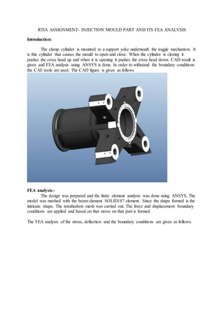
The clamp cylinder is mounted to a support yoke underneath the toggle mechanism. It
is this cylinder that causes the mould to open and close. When the cylinder is closing it
pushes the cross head up and when it is opening it pushes the cross head down. CAD result is
given and FEA analysis using ANSYS is done. In order to withstand the boundary conditions
the CAE tools are used. The CAD figure is given as follows
FEA analysis:-
The design was prepared and the finite element analysis was done using ANSYS. The
model was meshed with the beam element SOLID187 element. Since the shape formed is the
intricate shape. The tetrahedron mesh was carried out. The force and displacement boundary
conditions are applied and based on that stress on that part is formed
The FEA analysis of the stress, deflection and the boundary conditions are given as follows.
2. Fig 2- boundary conditions on the model
Fig 3- total deformation of clamp cylider
3. Fig 4- maximum principal stress distribution in clamp cylinder
Maximum principal stress:-117.90 Mpa.
Maximum deformation:-0.7502mm.
In order to optimize the maximum stress and the deformation in the given space and also
without varying the boundary condition of force and displacement we use the approach of
topology optimization of the clamped cylinder.
Topology Optimization of Clamp Cylinder:-
As observe with the FEA condition there are some places where the stress acting is
quite low that is that particular part is participating the lowest in the clamp design, there is a
possibility to optimize the design within prescribed region.
4. Fig 5- mesh model of clamp cylinder
For the purpose of optimization the material is considered as isotropic, homogeneous,
linear and temperature dependent. For these we use hyper mesh and meshed model of hyper
mesh is shown in figure. Iterations are carried out in order to optimize the density and 14
iterations were carried out in order to optimize the topography of the clamp cylinder.
5. Fig 6- Density distribution in clamp cylinder.(1st iteration)
Fig 7- Density distribution in clamp cylinder (14th iteration)
Fourteen iterations were carried out and based on the figure and the iteration we see
that blue areas which participate very less during load are reduced and density is distributed
and the yellow area which has relatively high density is reduced which reduces the overall
weight but increase the load and the displacement.
Modification BasedOn Optimization Result:-
From the result of topology optimization, geometry modifications have been done to
alter the original geometry.
6. Table 1-modification in original geometry of clamp cylinder
Fig 8- Difference between Existing and Modified model of Clamp Cylinder
The modified design is evaluated again using the FEA analysis. The boundary
conditions are the same as that of the original model. The displacement and force pattern are
as follows
7. Fig 9- total deformation modified
Fig 10-total stress modified
Maximum principal stress:- 119.61 Mpa.
Total deformation:- 0.75887mm.
8. Results And Discussion:-
The result obtained is quite simple by using the topological approach the deformation and the
load limits are increased decreasing the overall mass of the component
Table 2
Conclusion:-
With the conventional approach we are able to attain the permissible value but with
topographical approach we are able to reduce the weight upto 70 kg increasing the maximum
deformation and stress.