1. 1998-99 ENGINES
4.6L V8 - VIN W & 6
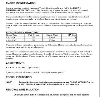
ENGINE IDENTIFICATION
Engine is identified by eighth character of Vehicle Identification Number (VIN). See ENGINE
IDENTIFICATION CODES table. VIN is located on top of instrument panel, near lower left corner of
windshield. VIN is also stamped on Vehicle Certification (VC) label mounted on left door pillar.
Engine code labels are located in engine compartment, in front of radiator and on right valve cover. Label
contains engine calibration number, engine build date, engine plant code and engine code.
Emission calibration number label is located on upper radiator shield. This label identifies engine calibration
number, engine code number and revision level. Numbers from labels are required when ordering replacement
parts.
ENGINE IDENTIFICATION CODES
Windsor and Romeo engine plants are producing the 4.6L engine. There are several differences between these
engines and many parts are not interchangeable.
The best way to determine manufacturer is by the VIN number. VIN W is a Romeo engine. VIN 6 is Windsor
engine. There are a couple external differences. The right valve cover on Windsor engine has 14 bolts, Romeo
engine has 11 bolts. Also on Windsor engine there is a W stamped on each valve cover in area of camshaft
sprocket.
ADJUSTMENTS
VALVE CLEARANCE ADJUSTMENT
Hydraulic valve lash adjusters are used. No valve adjustment is required.
TROUBLE SHOOTING
REMOVAL & INSTALLATION
Engine Type Fuel System Engine Plant VIN Code
4.6L SOHC SFI Romeo W
4.6L SOHC SFI Windsor 6
NOTE: To trouble shoot mechanical engine components, see ENGINE MECHANICAL in
BASIC TROUBLE SHOOTING article in GENERAL INFORMATION.
CAUTION: When battery is disconnected, vehicle computer and memory systems
1999 Ford Pickup F350 Super Duty
1998-99 ENGINES 4.6L V8 - VIN W & 6
1999 Ford Pickup F350 Super Duty
1998-99 ENGINES 4.6L V8 - VIN W & 6
Helpmelearn Repair Manuals
Friday, November 24, 2006 4:21:22 PM Page 1 © 2004 Mitchell Repair Information Company, LLC.
Helpmelearn Repair Manuals
Friday, November 24, 2006 4:21:31 PM Page 1 © 2004 Mitchell Repair Information Company, LLC.
2. FUEL PRESSURE RELEASE & FUEL LINE CONNECTIONS
1. Remove fuel cap to release fuel tank pressure. Connect EFI Pressure Gauge (T80L-9974-B) to relief
valve on right rear corner of fuel rail. Release pressure using valve on pressure gauge.
2. Before disconnecting fuel lines, disconnect negative battery cable. To disconnect fuel lines, remove
retaining clip from outside of fuel line coupling.
3. Install Spring Lock Coupling Remover (D87L-9280-A) for 3/8" line or (D87L-9280-B) for 1/2" line on
fuel line coupling so it enters cage opening. See Fig. 1 .
4. Push spring lock coupling remover into cage opening to release female fitting from garter spring. Pull
couplings apart. Remove spring lock coupling remover.
5. When installing fuel lines, fit NEW fuel resistant "O" rings (Brown) on fuel lines. Before installing,
lightly coat "O" rings with clean engine oil. Clean fittings, and replace garter spring (if necessary).
6. Install female fitting to male fitting and push until garter spring snaps over flared end of female fitting.
Ensure lines lock together and garter spring is over female fitting flared end.
7. Install retaining clip. Install Black retaining clip on fuel supply line and Gray clip on fuel return line.
Ensure horseshoe portion of clip is over coupling. DO NOT install retaining clip over rubber fuel line.
may lose memory data. Driveability problems may exist until computer
systems have completed a relearn cycle. See COMPUTER RELEARN
PROCEDURES article in GENERAL INFORMATION before disconnecting
battery.
NOTE: For reassembly reference, label all electrical connectors, vacuum hoses and
fuel lines before removal. Place mating marks on engine hood and other major
assemblies before removal.
WARNING: Fuel system is under pressure. Release pressure before servicing fuel
system components.
1999 Ford Pickup F350 Super Duty
1998-99 ENGINES 4.6L V8 - VIN W & 6
Helpmelearn Repair Manuals
Friday, November 24, 2006 4:21:22 PM Page 2 © 2004 Mitchell Repair Information Company, LLC.
3. Fig. 1: Disconnecting Fuel Lines
Courtesy of FORD MOTOR CO.
ENGINE
Removal (Expedition, Navigator & F150/250 Pickup)
1. Disconnect negative battery cable. Remove hood. Drain cooling system. Remove radiator. Discharge A/C
system using approved refrigerant recovery/recycling equipment. Release fuel pressure and disconnect
fuel lines. See FUEL PRESSURE RELEASE & FUEL LINE CONNECTIONS .
2. On Expedition and Navigator, remove air conditioning condenser and EGR manifold tube. Unclip mega
fuse holders from junction block bracket. Disconnect starter relay cables.
3. On all models, remove upper intake manifold. See INTAKE MANIFOLD . Remove bulkhead connector
cover. Disconnect necessary grounds and harness connectors. Disconnect necessary water and vacuum
connections. Unbolt power steering bracket, and position reservoir and bracket assembly aside. Remove
ignition coils and brackets.
4. Raise and support vehicle. Remove starter. Remove A/C compressor. Remove transmission cooler line
WARNING: Ensure air suspension system is shut off prior to hoisting, jacking or
towing an air suspension vehicle. Air suspension switch is located
behind right kick panel. Failure to do so can result in inflation or deflation
of air springs, which may cause vehicle to shift during servicing.
1999 Ford Pickup F350 Super Duty
1998-99 ENGINES 4.6L V8 - VIN W & 6
Helpmelearn Repair Manuals
Friday, November 24, 2006 4:21:23 PM Page 3 © 2004 Mitchell Repair Information Company, LLC.
4. from block mounted clip. Remove transmission inspection cover, torque converter bolts and
transmission-to engine bolts. Remove power steering retaining bolts and position power steering pump
aside.
5. Disconnect dual-converter "Y" pipe from exhaust manifolds, and position aside. Remove right and left
engine mount bolts. Lower vehicle and support transmission. Remove engine from vehicle.
Removal (E150)
1. Disconnect negative battery cable(s). Discharge A/C system using approved refrigerant
recovery/recycling equipment. Release fuel pressure and disconnect fuel lines. See FUEL PRESSURE
RELEASE & FUEL LINE CONNECTIONS .
2. Disconnect necessary harness and ground connections. Remove intake manifold. See INTAKE
MANIFOLD . Remove air deflector, radiator grille, radiator grille open panel and upper and lower core
supports. Remove radiator, fan shroud and cooling fan.
3. Remove headlight and side marker assemblies. Remove A/C condenser. Remove accessory drive belt.
Drain power steering fluid by disconnecting reservoir hose at power steering pump. Disconnect high
pressure hose at power steering pump. Remove lower radiator hose. Disconnect suction hose at receiver-
drier.
4. Raise and support vehicle. Disconnect dual-converter "Y" pipe at exhaust manifold. Drain engine oil and
remove oil filter. Remove oil cooler. Remove starter. Remove transmission-to-engine bolts.
5. Remove and discard torque converter nuts. Remove engine mount-to-subframe nuts. Lower vehicle.
Remove transmission oil filler tube. Support transmission. Remove engine from vehicle.
Installation (All Models)
1. To install, reverse removal procedure. Tighten all bolts to specification. See TORQUE
SPECIFICATIONS .
2. When installing fuel lines, fit NEW fuel resistant "O" rings (Brown) on fuel lines. Lightly coat "O" rings
with clean engine oil before installing. Clean fittings, and replace garter spring (if necessary).
3. Adjust all control cables and fluid levels. Refill cooling system. Evacuate and recharge A/C system.
INTAKE MANIFOLD
Removal (Upper & Lower)
1. Disconnect negative battery cable(s). Remove engine cover. Release fuel pressure and disconnect fuel
lines. See FUEL PRESSURE RELEASE & FUEL LINE CONNECTIONS . Drain cooling system.
Disconnect upper radiator hose from thermostat housing. Remove air cleaner and outlet tube assembly.
Remove throttle body. Remove EGR manifold tube.
2. Disconnect necessary vacuum and water connections. Disconnect necessary wiring connections. Remove
spark plug wires. Remove accessory drive belt. Remove alternator. Remove upper intake manifold-to-
head retaining bolts in reverse order of tightening sequence. See Fig. 3 .
3. Lift upper and lower intake manifold assembly. Disconnect electrical connector at manifold tuning valve,
and remove intake manifold assembly from vehicle. Remove upper intake manifold-to-lower intake
manifold mounting bolts. Remove pushpin retainer from front of manifold insulator. Separate manifold
1999 Ford Pickup F350 Super Duty
1998-99 ENGINES 4.6L V8 - VIN W & 6
Helpmelearn Repair Manuals
Friday, November 24, 2006 4:21:23 PM Page 4 © 2004 Mitchell Repair Information Company, LLC.
5. insulator from lower intake manifold. See Fig. 2 . Separate upper and lower intake manifolds.
Installation
1. To install, reverse removal procedure. Use NEW gaskets and "O" rings. Lubricate fuel injector "O" rings
with Light Grade Oil (ESE-M2C39-F) before installing.
2.
Ensure alignment tabs on intake manifold gaskets align with holes in cylinder head. Tighten upper intake
manifold to lower intake manifold bolts to specification in sequence. See Fig. 3 . Tighten upper intake
manifold-to-head bolts to specification in sequence. See Fig. 4 . See TORQUE SPECIFICATIONS .
3. When installing fuel lines, fit NEW fuel resistant "O" rings (Brown) on fuel lines. Lightly coat "O" rings
with clean engine oil before installing. Clean fittings, and replace garter spring (if necessary).
4. To install remaining components, reverse removal procedure. Adjust all control cables and fluid levels.
Refill cooling system. When installing spark plug wires, ensure wires are in correct position on coils. See
appropriate SERVICE & ADJUSTMENT SPECIFICATIONS article in ENGINE PERFORMANCE.
CAUTION: Intake manifold bolts must be retightened to specification after
engine has reached normal operating temperature.
1999 Ford Pickup F350 Super Duty
1998-99 ENGINES 4.6L V8 - VIN W & 6
Helpmelearn Repair Manuals
Friday, November 24, 2006 4:21:23 PM Page 5 © 2004 Mitchell Repair Information Company, LLC.
6. Fig. 2: Exploded View Of Upper & Lower Intake Manifold
Courtesy of FORD MOTOR CO.
1999 Ford Pickup F350 Super Duty
1998-99 ENGINES 4.6L V8 - VIN W & 6
Helpmelearn Repair Manuals
Friday, November 24, 2006 4:21:23 PM Page 6 © 2004 Mitchell Repair Information Company, LLC.
7. Fig. 3: Upper Intake Manifold-To-Lower Intake Manifold Bolt Tightening Sequence
Courtesy of FORD MOTOR CO.
1999 Ford Pickup F350 Super Duty
1998-99 ENGINES 4.6L V8 - VIN W & 6
Helpmelearn Repair Manuals
Friday, November 24, 2006 4:21:23 PM Page 7 © 2004 Mitchell Repair Information Company, LLC.
8. Fig. 4: Upper Intake Manifold-To-Head Bolt Tightening Sequence
Courtesy of FORD MOTOR CO.
EXHAUST MANIFOLD
Removal (All Models)
Raise and support vehicle. Remove front fender splash shield. If removing left side, remove EGR manifold tube
and brake vacuum booster hose bracket. On either side, disconnect exhaust manifold flange. Remove exhaust
manifold retaining nuts in reverse order of tightening sequence. See Fig. 5 . Remove exhaust manifold and
WARNING: Ensure air suspension system is shut off prior to hoisting, jacking or
towing an air suspension vehicle. Air suspension switch is located
behind right kick panel. Failure to do so can result in inflation or deflation
of air springs, which may cause vehicle to shift during servicing.
1999 Ford Pickup F350 Super Duty
1998-99 ENGINES 4.6L V8 - VIN W & 6
Helpmelearn Repair Manuals
Friday, November 24, 2006 4:21:23 PM Page 8 © 2004 Mitchell Repair Information Company, LLC.
9. gasket.
Installation
To install, reverse removal procedure. Tighten exhaust manifold nuts to specification in sequence. See Fig. 5 .
See TORQUE SPECIFICATIONS .
Fig. 5: Exhaust Manifold Bolt Tightening Sequence
Courtesy of FORD MOTOR CO.
CYLINDER HEAD
Removal
1. On 1998 models, disconnect negative battery cable(s). Remove intake manifold. See INTAKE
MANIFOLD . On 1999 models, remove engine. See ENGINE . On all models, remove exhaust
manifold. See EXHAUST MANIFOLD .
2. Remove timing chains. See TIMING CHAINS . On 1998 models, disconnect heater hoses. On 1998
Expedition, F150, F250 and Navigator, remove heater pipe-to-engine mounting studs. Remove heater
pipe and discard "O" ring. On all models, remove cylinder head bolts in sequence. See Fig. 6 or Fig. 7 .
Remove cylinder head and gasket.
Inspection
Check cylinder head for warpage, cracks and damage. Maximum warpage information is not available from
manufacturer.
Installation
CAUTION: If cylinder head-to-block surface refinishing is necessary, DO NOT remove
more than .010" (.25 mm) from cylinder head surface.
1999 Ford Pickup F350 Super Duty
1998-99 ENGINES 4.6L V8 - VIN W & 6
Helpmelearn Repair Manuals
Friday, November 24, 2006 4:21:23 PM Page 9 © 2004 Mitchell Repair Information Company, LLC.
10. 1. Ensure proper gaskets are installed. Right and left cylinder head gaskets are not interchangeable. Rotate
crankshaft 90 degrees counterclockwise from vertical position. See STEP 1 in illustration. See Fig. 9 .
Ensure no piston is at TDC.
2.
Coat bolt head-to-cylinder head surfaces with engine oil. DO NOT oil threads of cylinder head bolts.
Ensure rear cylinder head bolts are installed in cylinder head and secured by rubber bands before
installing cylinder head, if necessary. See Fig. 8 . Install cylinder heads.
3. Tighten cylinder head bolts to specification and in sequence. See Fig. 6 or Fig. 7 . See TORQUE
SPECIFICATIONS . On 1998 Expedition, F150, F250 and Navigator, install a new "O" ring on heater
pipe. Lubricate "O" ring with clean coolant and install heater pipe. Tighten heater pipe-to-engine
mounting studs to specification. If camshaft positioner was not used during cylinder head installation,
rotate camshafts using flats matched at center of camshaft until both cams are in time. Install Camshaft
Positioner (T91P-6256-A) on flats of camshaft. This will prevent camshafts from rotating.
4. Rotate crankshaft 45 degrees clockwise. See STEP 2 in illustration. See Fig. 9 . This will position
crankshaft so cylinder No. 1 is at TDC. DO NOT rotate crankshaft past TDC position. Timing chains can
now be installed. See TIMING CHAINS . To install remaining components, reverse removal procedure.
CAUTION: Position camshaft so valves DO NOT extend below cylinder head
surface, or ensure Camshaft Positioner (T93P-6256-A) is installed
before installing cylinder head. See Fig. 10 . Install NEW cylinder
head bolts. DO NOT reuse bolts.
1999 Ford Pickup F350 Super Duty
1998-99 ENGINES 4.6L V8 - VIN W & 6
Helpmelearn Repair Manuals
Friday, November 24, 2006 4:21:23 PM Page 10 © 2004 Mitchell Repair Information Company, LLC.
11. 1999 Ford Pickup F350 Super Duty
1998-99 ENGINES 4.6L V8 - VIN W & 6
Helpmelearn Repair Manuals
Friday, November 24, 2006 4:21:23 PM Page 11 © 2004 Mitchell Repair Information Company, LLC.
12. Fig. 6: Cylinder Head Bolt Removal & Installation Sequence (Romeo Engine)
Courtesy of FORD MOTOR CO.
1999 Ford Pickup F350 Super Duty
1998-99 ENGINES 4.6L V8 - VIN W & 6
Helpmelearn Repair Manuals
Friday, November 24, 2006 4:21:23 PM Page 12 © 2004 Mitchell Repair Information Company, LLC.
13. 1999 Ford Pickup F350 Super Duty
1998-99 ENGINES 4.6L V8 - VIN W & 6
Helpmelearn Repair Manuals
Friday, November 24, 2006 4:21:23 PM Page 13 © 2004 Mitchell Repair Information Company, LLC.
14. Fig. 7: Cylinder Head Bolt Removal & Installation Sequence (Windsor Engine)
Courtesy of FORD MOTOR CO.
Fig. 8: Securing Cylinder Head Bolts
Courtesy of FORD MOTOR CO.
1999 Ford Pickup F350 Super Duty
1998-99 ENGINES 4.6L V8 - VIN W & 6
Helpmelearn Repair Manuals
Friday, November 24, 2006 4:21:23 PM Page 14 © 2004 Mitchell Repair Information Company, LLC.
15. Fig. 9: Positioning Crankshaft
Courtesy of FORD MOTOR CO.
1999 Ford Pickup F350 Super Duty
1998-99 ENGINES 4.6L V8 - VIN W & 6
Helpmelearn Repair Manuals
Friday, November 24, 2006 4:21:23 PM Page 15 © 2004 Mitchell Repair Information Company, LLC.
16. Fig. 10: Installing Camshaft Positioner
Courtesy of FORD MOTOR CO.
VALVE COVERS
Removal (Left)
Disconnect negative battery cable(s). Remove air cleaner. On Expedition, Navigator and F150, unbolt power
steering reservoir bracket and position reservoir, and bracket assembly aside. On all models, disconnect PCV
hose from valve cover. Remove EGR manifold tube. Disconnect fuel injection electrical connections. Loosen
valve cover retaining bolts. Retaining bolts are part of valve cover and should not be removed. Remove valve
cover and gasket.
Removal (Right)
On E150, remove air cleaner, oil filler tube and engine cover. On all models, disconnect PCV valve hose from
valve cover. Disconnect electrical connections as necessary. Disconnect heater water hose. Loosen valve cover
1999 Ford Pickup F350 Super Duty
1998-99 ENGINES 4.6L V8 - VIN W & 6
Helpmelearn Repair Manuals
Friday, November 24, 2006 4:21:23 PM Page 16 © 2004 Mitchell Repair Information Company, LLC.
17. retaining bolts. Retaining bolts are part of valve cover and should not be removed. Remove valve cover and
gasket.
Installation (All Models Left & Right)
1. Clean sealing surfaces on valve cover and cylinder head. Using gasket adhesive, glue valve cover gasket
into valve cover. Apply a bead of silicone gasket adhesive to seam where cylinder head and front cover
meet.
2. Install valve cover and valve cover mounting bolts. To complete installation, reverse removal procedure.
Tighten bolts to specification. See Fig. 11 . See TORQUE SPECIFICATIONS .
3. When installing fuel lines, fit NEW fuel resistant "O" rings (Brown) on fuel lines. Lightly coat "O" rings
with clean engine oil before installing. Clean fittings, and replace garter spring (if necessary).
1999 Ford Pickup F350 Super Duty
1998-99 ENGINES 4.6L V8 - VIN W & 6
Helpmelearn Repair Manuals
Friday, November 24, 2006 4:21:23 PM Page 17 © 2004 Mitchell Repair Information Company, LLC.
18. Fig. 11: Valve Cover Bolt Tightening Sequence
Courtesy of FORD MOTOR CO.
FRONT COVER OIL SEAL
1999 Ford Pickup F350 Super Duty
1998-99 ENGINES 4.6L V8 - VIN W & 6
Helpmelearn Repair Manuals
Friday, November 24, 2006 4:21:23 PM Page 18 © 2004 Mitchell Repair Information Company, LLC.
19. Removal
1. Disconnect negative battery cable. Release belt tensioner, and remove accessory drive belt. Remove
cooling fan and fan shroud. On E150, remove air cleaner assembly.
2. Raise and support vehicle. Remove crankshaft damper retaining bolt and washer. Using Puller (T58P-
6316-D), remove crankshaft damper. Using Seal Remover (T74P-6700-A), remove oil seal from front
cover.
Installation
To install, reverse removal procedure. Lubricate oil seal bore and seal lip with engine oil before installing. Use
Seal Installer (T88T-6701-A1 and A2) to install oil seal. Apply silicone sealant to keyway of crankshaft damper
before installing. Tighten bolts to specification. See TORQUE SPECIFICATIONS .
FRONT COVER
Removal
1. Disconnect negative battery cable. Remove cooling fan and shroud. Remove radiator. Remove accessory
drive belt. Remove water pump pulley. Raise and support vehicle. Remove power steering pump, and
secure aside.
2. Drain engine oil. Remove oil pan-to-front cover bolts. Remove crankshaft damper retaining bolt and
washer. Using Puller (T58P-6316-D), remove crankshaft damper. Lower vehicle. Remove A/C refrigerant
line retainer from right coil bracket, if necessary.
3. Remove both valve covers. See VALVE COVERS . Disconnect ignition coils, radio interference
capacitor and camshaft position sensor harness connectors. Remove coil brackets and lay coil brackets
with spark plug wires on top of engine.
4. Remove idler belt pulley. Disconnect crankshaft position sensor and remove sensor. Remove front cover
retaining bolts/studs in reverse order of tightening sequence. See Fig. 12 . Remove front cover and
gasket.
Installation
To install, reverse removal procedure. Apply Sealant (E3AZ-19562-A) at front cover-to-oil pan, cylinder block
and valve cover areas. Apply silicone sealant to keyway of crankshaft damper before installing. Tighten bolts to
specification. See Fig. 12 . See TORQUE SPECIFICATIONS .
WARNING: Ensure air suspension system is shut off prior to hoisting, jacking or
towing an air suspension vehicle. Air suspension switch is located
behind right kick panel. Failure to do so can result in inflation or deflation
of air springs, which may cause vehicle to shift during servicing.
WARNING: Ensure air suspension system is shut off prior to hoisting, jacking or
towing an air suspension vehicle. Air suspension switch is located
behind right kick panel. Failure to do so can result in inflation or deflation
of air springs, which may cause vehicle to shift during servicing.
1999 Ford Pickup F350 Super Duty
1998-99 ENGINES 4.6L V8 - VIN W & 6
Helpmelearn Repair Manuals
Friday, November 24, 2006 4:21:23 PM Page 19 © 2004 Mitchell Repair Information Company, LLC.
20. Fig. 12: Front Cover Tightening Sequence
Courtesy of FORD MOTOR CO.
TIMING CHAINS
Removal
1. Remove valve covers. See VALVE COVERS . Remove front cover. See FRONT COVER . Remove
crankshaft position sensor pulse wheel from crankshaft.
2.
CAUTION: DO NOT rotate engine with timing chain removed. Damage to
valve/piston may result.
1999 Ford Pickup F350 Super Duty
1998-99 ENGINES 4.6L V8 - VIN W & 6
Helpmelearn Repair Manuals
Friday, November 24, 2006 4:21:23 PM Page 20 © 2004 Mitchell Repair Information Company, LLC.
21. Rotate crankshaft until No. 1 piston is at TDC. This positions crankshaft keyway 45 degrees from vertical
position. See Fig. 13 . Camshaft keyways will point toward crankshaft.
3.
Install Camshaft Positioner (T96T-6256-AR) on flat area near rear of camshaft. See Fig. 10 . Remove
retaining bolts, right chain tensioner, right tensioner arm and right chain guide. See Fig. 14 .
4. Remove right timing chain and crankshaft sprocket. Note direction of sprocket for installation reference.
If necessary for clearance, remove retaining bolt, washer, camshaft sprocket and spacer.
5.
Remove retaining bolts, left chain tensioner, left tensioner arm and left chain guide. See Fig. 14 . Remove
left timing chain and crankshaft sprocket. Note direction of sprocket for installation reference. If
necessary for clearance, remove retaining bolt, washer, camshaft sprocket and spacer.
Inspection
Inspect components for damage. Inspect friction surfaces on tensioner arms and chain guides for wear. Replace
components if necessary. If tensioner arms or guides are worn or damaged, remove and clean oil pan. Also,
replace oil pump screen cover and tube.
Installation
1. Install spacers, camshaft sprockets and retaining bolts. Ensure components are installed in original
locations. Tighten bolts to specification. See TORQUE SPECIFICATIONS .
2. Install Camshaft Positioner (T92P-6256-A) on flat areas of camshaft if not previously installed. See Fig.
10 .
3.
Install crankshaft sprocket for left timing chain. If copper links are not visible on timing chain, fold
timing chain in half and mark each end link for timing purposes. See Fig. 15 . These links will be referred
to as copper links when installing.
4. Ensure No. 1 piston is at TDC. This positions crankshaft keyway 45 degrees from vertical position. See
CAUTION: Mark component location for reassembly reference. Components
must be installed in original locations.
CAUTION: DO NOT rotate engine with timing chain(s) removed. Damage to
valve/piston may result.
CAUTION: If components are replaced due to damage, ensure crankshaft is rotated
so pistons are below deck surface (crankshaft keyway at 90 degrees) to
prevent contact with valves. See STEP 1 in Fig. Fig. 9 . Ensure camshaft
positioner is installed on camshaft(s) before installing timing chain(s).
CAUTION: Install crankshaft sprocket halves with hubs facing each other. See
Fig. 15 .
1999 Ford Pickup F350 Super Duty
1998-99 ENGINES 4.6L V8 - VIN W & 6
Helpmelearn Repair Manuals
Friday, November 24, 2006 4:21:23 PM Page 21 © 2004 Mitchell Repair Information Company, LLC.
22. Fig. 9 . Crankshaft keyway will point toward camshaft.
5. Install left timing chain on camshaft and crankshaft sprockets so copper link aligns with timing mark on
sprockets. See Fig. 13 . Install crankshaft sprocket for right timing chain. Ensure sprocket is properly
installed.
6. Install right timing chain on camshaft and crankshaft sprockets so copper link aligns with timing mark on
sprockets. Install Crankshaft Positioner (T93P-6256-A), to prevent crankshaft movement. Lubricate
tensioner arms with engine oil. Install tensioner arms. Install chain guides.
7. Chain tensioners must be bled down so tensioner plunger is compressed in housing before installing.
Place chain tensioner in soft-jaw vise. Using small pick, hold ratchet lock mechanism away from ratchet
stem. See Fig. 16 . Slowly close vise to depress tensioner plunger.
8. When tensioner plunger is compressed in housing, continue to hold ratchet lock mechanism and install
lock pin in hole on tensioner housing. Ensure ratchet stem is even with tensioner housing before installing
lock pin. See Fig. 16 .
9. Using "C" clamp or suitable tool, remove all slack from timing chain by applying pressure to tensioner
arm. While holding pressure on arm, install both chain tensioners and retaining bolts on cylinder block.
Tighten bolts to specification. See TORQUE SPECIFICATIONS .
10. Remove lock pins from both chain tensioners. Ensure all timing marks align. See Fig. 13 . To check
accuracy of valve timing, remove No. 1 spark plug. Using a dial indicator, check for maximum intake
valve lift. Maximum intake valve lift should occur at 114 degrees after TDC.
11. To install remaining components, reverse removal procedure. Before installing valve cover, apply
silicone sealant at front cover-to-cylinder block areas.
12. When installing fuel lines, fit NEW fuel resistant "O" rings (Brown) on fuel lines. Lightly coat "O" rings
with clean engine oil before installing. Clean fittings, and replace garter spring (if necessary).
1999 Ford Pickup F350 Super Duty
1998-99 ENGINES 4.6L V8 - VIN W & 6
Helpmelearn Repair Manuals
Friday, November 24, 2006 4:21:23 PM Page 22 © 2004 Mitchell Repair Information Company, LLC.
23. Fig. 13: Identifying Timing Marks
Courtesy of FORD MOTOR CO.
Fig. 14: Exploded View Of Timing Chain & Components
Courtesy of FORD MOTOR CO.
1999 Ford Pickup F350 Super Duty
1998-99 ENGINES 4.6L V8 - VIN W & 6
Helpmelearn Repair Manuals
Friday, November 24, 2006 4:21:24 PM Page 23 © 2004 Mitchell Repair Information Company, LLC.
24. Fig. 15: Identifying Crankshaft Sprocket & Timing Chain Timing Marks
Courtesy of FORD MOTOR CO.
Fig. 16: Compressing Timing Chain Tensioner Plunger
Courtesy of FORD MOTOR CO.
CAMSHAFT FOLLOWER & LASH ADJUSTER
Removal
1. Remove valve covers. See VALVE COVERS . Rotate crankshaft until piston in cylinder to be serviced
1999 Ford Pickup F350 Super Duty
1998-99 ENGINES 4.6L V8 - VIN W & 6
Helpmelearn Repair Manuals
Friday, November 24, 2006 4:21:24 PM Page 24 © 2004 Mitchell Repair Information Company, LLC.
25. is at bottom of its stroke, and camshaft lobe is at base circle.
2. Install Valve Spring Spacer (T91P-6565-AH) between valve spring coils to prevent valve stem oil seal
damage. Using Valve Spring Compressor (T91P-6565-A), compress valve spring. Remove camshaft
follower and lash adjuster.
Inspection
Inspect components for damage. Measure lash adjuster O.D. and oil clearance. Replace components if damaged
or measurements are not within specification. See VALVE LASH ADJUSTER table under ENGINE
SPECIFICATIONS.
Installation
1. To install, reverse removal procedure. Coat components with engine oil before installing. Before
installing valve cover, apply silicone sealant at front cover-to-cylinder block areas.
2. When installing fuel lines, fit NEW fuel resistant "O" rings (Brown) on fuel lines. Lightly coat "O" rings
with clean engine oil before installing. Clean fittings, and replace garter spring (if necessary).
CAMSHAFT
Removal
Remove camshaft followers and lash adjusters. See CAMSHAFT FOLLOWER & LASH ADJUSTER .
Remove timing chains. See TIMING CHAINS . Remove camshaft cap bolts in reverse order of tightening
sequence. See Fig. 17 . On Romeo engines, tap camshaft caps in designated areas to remove camshaft caps. See
Fig. 18 . On both engines. remove camshaft caps and camshaft.
Inspection
Measure camshaft bore I.D. and journal O.D. to determine oil clearance. Measure lobe lift. Replace camshaft if
measurements are not within specification. See CAMSHAFT table under ENGINE SPECIFICATIONS.
Installation
1.
Coat components with engine oil, and install components. Install all bolts for both camshaft caps, and
tighten them finger tight. Tighten bolts to 72-106 INCH lbs. (8-12 N.m) in sequence. See Fig. 17 .
Loosen all bolts 2 turns. Retighten bolts to 72-106 INCH lbs. (8-12 N.m) in sequence. Repeat procedure
for each camshaft.
CAUTION: Before installing, ensure lash adjuster is full of oil and plunger does not
have more than .059" (1.49 mm) travel. Ensure piston is at bottom of
stroke and camshaft lobe is on base circle.
CAUTION: Ensure proper procedure is used when installing timing chains to
prevent engine damage. See TIMING CHAINS .
1999 Ford Pickup F350 Super Duty
1998-99 ENGINES 4.6L V8 - VIN W & 6
Helpmelearn Repair Manuals
Friday, November 24, 2006 4:21:24 PM Page 25 © 2004 Mitchell Repair Information Company, LLC.
26. 2. Ensure camshaft end play is within specification. See CAMSHAFT table under ENGINE
SPECIFICATIONS. To install remaining components, reverse removal procedure. Tighten all bolts to
specification. See TORQUE SPECIFICATIONS .
Fig. 17: Camshaft Cap Bolt Tightening Sequence
Courtesy of FORD MOTOR CO.
1999 Ford Pickup F350 Super Duty
1998-99 ENGINES 4.6L V8 - VIN W & 6
Helpmelearn Repair Manuals
Friday, November 24, 2006 4:21:24 PM Page 26 © 2004 Mitchell Repair Information Company, LLC.
27. Fig. 18: Removing Camshaft Caps (Romeo Engine)
Courtesy of FORD MOTOR CO.
CRANKSHAFT REAR OIL SEAL
Removal
1. Remove transmission. See TRANSMISSION REMOVAL & INSTALLATION - TRUCKS article in
TRANSMISSION SERVICING. Remove oil pan. See OIL PAN . Remove flywheel. Remove rear oil
seal retainer.
2. Using Rear Crankshaft Slinger Remover (T95P-6701-AH) and Slide Hammer (T50T-100-A), remove oil
slinger. Using Rear Crankshaft Seal Remover (T95P-6701-EH), remove oil seal.
Installation
Clean and inspect all mating surface. Install rear seal retainer. See Fig. 19 . Using Rear Crankshaft Seal
Replacer (T95P-6701-BH) and Rear Crankshaft Seal Adapter (T95P-6701-DH), install rear seal. With rear
crankshaft adapter still installed, use Rear Crankshaft Slinger Replacer (T95P-6701-CH) and seal replacer to
install seal slinger. To complete installation, reverse removal procedure. Tighten bolts to specifications. See
TORQUE SPECIFICATIONS .
1999 Ford Pickup F350 Super Duty
1998-99 ENGINES 4.6L V8 - VIN W & 6
Helpmelearn Repair Manuals
Friday, November 24, 2006 4:21:24 PM Page 27 © 2004 Mitchell Repair Information Company, LLC.
28. Fig. 19: Seal Retainer Bolt Tightening Sequence
Courtesy of FORD MOTOR CO.
WATER PUMP
Removal & Installation
1. Drain cooling system. Remove cooling fan and shroud. Release belt tensioner, and remove accessory
drive belt. Remove water pump pulley. Remove retaining bolts, water pump and "O" ring.
2. To install, reverse removal procedure. Lubricate "O" ring with coolant before installing. Tighten bolts to
specification. See TORQUE SPECIFICATIONS . Fill cooling system.
OIL PAN
Removal (E150)
1. Remove the intake manifold. See INTAKE MANIFOLD . Remove the plastic rivet retainers and the air
deflector. Disconnect the upper radiator hose from the radiator. Disconnect the overflow hose from the
radiator. The large clutch assembly nut has a right-hand thread and must be rotated counterclockwise to
remove it. Remove the fan and fan clutch from the water pump pulley. Remove the bolts and lift the fan
shroud, fan and fan clutch from the vehicle.
WARNING: Ensure air suspension system is shut off prior to hoisting, jacking or
towing an air suspension vehicle. Air suspension switch is located
behind right kick panel. Failure to do so can result in inflation or deflation
of air springs, which may cause vehicle to shift during servicing.
1999 Ford Pickup F350 Super Duty
1998-99 ENGINES 4.6L V8 - VIN W & 6
Helpmelearn Repair Manuals
Friday, November 24, 2006 4:21:24 PM Page 28 © 2004 Mitchell Repair Information Company, LLC.
29. 2. Remove the retainers and the shield between radiator and radiator support. Remove the nut retaining the
transmission filler tube at the rear of the right cylinder head and position the tube aside. Detach the wiring
harness retainer. Remove the stud bolts. See Fig. 20 . Remove the upper 2 transmission-to-engine bolts.
3. Assemble 3-Bar Engine Support, Modular Lifting Bar (303-F047) and Lift Bar Adapter (303-F694).
Install the special tools on engine and support the engine. See Fig. 21 . Raise and support the vehicle.
Drain the engine oil, and remove the oil filter. Remove the nuts retaining the front engine support
insulator to the front engine support bracket.
4. Remove the flywheel inspection plate. Lower the vehicle. Using the 3-Bar Engine Support, raise the
engine 10-1/4 inches from the crankshaft pulley to the lower edge of the No. 1 crossmember. Raise the
vehicle. Remove the bolts and partially lower the oil pan.
5. Remove the bolts retaining the oil pump screen cover and tube and let the bolts drop into the oil pan.
Remove the oil pan at the rear of the engine. Clean the mating surfaces and clean the oil pan thoroughly.
Inspect the oil pan gasket.
Fig. 20: Locating 2 Stud Bolts
Courtesy of FORD MOTOR CO.
1999 Ford Pickup F350 Super Duty
1998-99 ENGINES 4.6L V8 - VIN W & 6
Helpmelearn Repair Manuals
Friday, November 24, 2006 4:21:24 PM Page 29 © 2004 Mitchell Repair Information Company, LLC.
30. Fig. 21: Setting Up 3-Bar Engine Support
Courtesy of FORD MOTOR CO.
Installation
1. Clean and inspect the mating surfaces and install a new "O" ring seal. Lubricate with Motor Oil. To
install, reverse the removal procedure. Tighten the oil pan bolts in three stages, in the sequence shown.
See Fig. 22 . See TORQUE SPECIFICATIONS .
2. Lower the vehicle. Remove the special tools. Raise the vehicle. Install the nuts retaining the front engine
support insulators to the front engine support brackets. Install the flywheel inspection plate. Install the top
2 transmission-to-engine bolts. Tighten bolts to specification. See TORQUE SPECIFICATIONS .
CAUTION: Make sure the oil pump screen cover and tube "O" ring seal is in place and
not damaged. A missing or damaged "O" ring seal can cause foam in the
lubrication system, low oil pressure and severe engine damage.
1999 Ford Pickup F350 Super Duty
1998-99 ENGINES 4.6L V8 - VIN W & 6
Helpmelearn Repair Manuals
Friday, November 24, 2006 4:21:24 PM Page 30 © 2004 Mitchell Repair Information Company, LLC.
31. Fig. 22: Oil Pan Bolt Tightening Sequence (All Models)
Courtesy of FORD MOTOR CO.
Removal (4x2)
1999 Ford Pickup F350 Super Duty
1998-99 ENGINES 4.6L V8 - VIN W & 6
Helpmelearn Repair Manuals
Friday, November 24, 2006 4:21:24 PM Page 31 © 2004 Mitchell Repair Information Company, LLC.
32. 1. Disconnect the battery ground cable. Drain the cooling system. Remove radiator air deflector screws and
remove the radiator air deflector.
2. Remove the accelerator control splash shield. Disconnect the intake air temperature sensor electrical
connector. Disconnect the PCV hose and the idle air control valve inlet tube. Loosen the clamps and
remove the air cleaner outlet tube and resonator.
3. Remove the throttle return spring. To disconnect the accelerator cable from the throttle body cam, roll the
throttle body cam forward and slide the accelerator cable from the throttle body cam. If equipped, to
disconnect the speed control actuator cable from the throttle body, remove the cable bracket bolt and
disconnect the speed control actuator cable from the throttle body cam and position aside.
4. Disconnect PCV hose to throttle body adapter. Disconnect PCV intake manifold. Disconnect PCV hose to
valve cover.
5. Disconnect the following vacuum connections:
EGR Vacuum Connector
Engine Vacuum Supply Port
EVR Vacuum Connector
Fuel Pressure Regulator
6. Remove the nut on EGR valve mounting bolt. Disconnect the EGR valve to exhaust manifold tube upper
fitting. Disconnect the idle air control electrical connector. Disconnect the brake booster vacuum hose.
Remove the throttle body adapter bolts and the throttle body adapter assembly.
7. Remove the fan shroud bolts. Position the fan shroud aside. Remove the drive belt. Remove the generator
bracket bolts. Disconnect the ignition wire from the generator bracket. Remove the generator mounting
bolts. Disconnect the generator electrical connections. Remove the generator.
8. Install the 3-Bar Modular Engine Support Bracket (303-F070) on the engine using the generator
mounting bolts. Raise and support the vehicle. Remove the drain plug and drain the engine oil. Remove
the motor mount thru-bolts.
9. Lower the vehicle. Raise the engine using the three bar engine support. Raise the vehicle on the hoist. Be
careful when removing the oil pan gasket. The oil pan gasket is reusable if it is not damaged. Remove the
oil pan bolts. Position the oil pan aside to gain access to the oil pump screen cover and tube.
10. Remove the bolt securing the rear of the oil pump screen cover and tube. Remove the bolts securing the
front of the oil pump screen cover and tube. Remove the oil pan and the oil pump screen cover and tube
together.
Installation
1.
CAUTION: Do not use metal scrapers, wire brushes, power abrasive discs or other
abrasive means to clean the sealing surfaces. These tools cause
scratches and gouges which make leak paths. Use a plastic scraping tool
to remove all traces of old sealant.
CAUTION: Make sure the oil pump screen cover and tube "O" ring seal is in
place and not damaged. A missing or damaged "O" ring seal can
1999 Ford Pickup F350 Super Duty
1998-99 ENGINES 4.6L V8 - VIN W & 6
Helpmelearn Repair Manuals
Friday, November 24, 2006 4:21:24 PM Page 32 © 2004 Mitchell Repair Information Company, LLC.
33. Clean and inspect the mating surfaces. Clean and inspect the mating surfaces and install a new "O" ring
seal. Lubricate with motor oil. Position the oil pan gasket, the oil pan and the oil pump screen cover and
tube together to the cylinder block. Install the oil pump screen cover and tube bolts.
2.
Apply the silicone at the engine front cover to cylinder block mating surface. See Fig. 23 . Apply the
silicone at the rear oil seal retainer to cylinder block sealing surface. See Fig. 24 .
3. Position the oil pan gasket. Install the bolts and torque in the three stages, in the sequence shown. See
Fig. 22 . See TORQUE SPECIFICATIONS . Lower the vehicle. Lower the engine and remove the 3-
bar engine support.
4. Raise the vehicle on the hoist. Install the motor mount bolts. Install the drain plug. Lower the vehicle.
Remove the 3-bar engine support bracket. Connect the generator electrical connections. Position the
generator and install the bolts. Install the bracket bolts finger tight, then tighten to specification. See
TORQUE SPECIFICATIONS . Attach the ignition wire to the generator bracket. Install the drive belt.
5. Position the fan shroud and install the bolts. Install a new gasket and the throttle body adapter assembly
and tighten in two stages. See TORQUE SPECIFICATIONS . Connect the brake booster vacuum
supply. Connect the IAC electrical connector. Connect the upper EGR valve to exhaust manifold tube
nut. Tighten the fitting in two stages. See TORQUE SPECIFICATIONS .
6. Install the EGR backpressure transducer nut. Connect crankcase ventilation hose to throttle body adapter.
Connect PCV intake manifold. Connect crankcase ventilation hose to valve cover.
7. Connect the following vacuum connections:
EGR Vacuum Connector.
Engine Vacuum Supply Port.
EVR Vacuum Connector.
Fuel Pressure Regulator.
8. Connect the TPS electrical connector. If equipped, install the speed control actuator cable on the throttle
body. To connect the accelerator cable to the throttle body cam, roll the throttle body cam forward and
slide the accelerator cable into the throttle body cam. Install the throttle return spring.
9. Install the air cleaner outlet tube and resonator and tighten the clamps. Connect the PCV hose and the idle
air control valve inlet tube. Connect the intake air temperature sensor electrical connector. Install the
accelerator control splash shield. Install the radiator air deflector. Connect the battery ground cable. Fill
the engine with Premium 5W-30 motor oil. Fill and bleed the cooling system.
cause foam in the lubrication system, low oil pressure and severe
engine damage.
NOTE: If the oil pan is not secured within four minutes, the sealant must be
removed and the sealing area cleaned with Metal Surface Cleaner (F4AZ-
19A536-RA). Allow to dry until there is no sign of wetness, or four minutes,
whichever is longer. Failure to follow this procedure may result in future
oil leakage.
1999 Ford Pickup F350 Super Duty
1998-99 ENGINES 4.6L V8 - VIN W & 6
Helpmelearn Repair Manuals
Friday, November 24, 2006 4:21:24 PM Page 33 © 2004 Mitchell Repair Information Company, LLC.
34. Fig. 23: Locating Silicon Application (Front)
Courtesy of FORD MOTOR CO.
1999 Ford Pickup F350 Super Duty
1998-99 ENGINES 4.6L V8 - VIN W & 6
Helpmelearn Repair Manuals
Friday, November 24, 2006 4:21:24 PM Page 34 © 2004 Mitchell Repair Information Company, LLC.
35. Fig. 24: Locating Silicon Application (Rear)
Courtesy of FORD MOTOR CO.
Removal (4x4)
1. Turn the air suspension switch off. Raise the vehicle on the hoist. Drain the engine oil.
2. Support the front axle housing with a jack stand. To remove front axle housing support, remove the front
axle mount bolt, remove the axle support bolts and remove the axle support. See Fig. 25 .
3.
Remove the right and front axle housing mount bolts and lower the axle to allow clearance for the oil pan
to be removed. See Fig. 26 . Remove the oil pan.
4.
CAUTION: The air suspension switch must be turned off prior to raising the vehicle.
Failure to do so can result in unexpected inflation or deflation of the air
springs, which could result in shifting of the vehicle during the repair
operation.
CAUTION: Use care when lowering the front axle housing, or the vacuum lines
to the axle solenoid may become disconnected or damaged.
1999 Ford Pickup F350 Super Duty
1998-99 ENGINES 4.6L V8 - VIN W & 6
Helpmelearn Repair Manuals
Friday, November 24, 2006 4:21:24 PM Page 35 © 2004 Mitchell Repair Information Company, LLC.
36. Remove and discard the oil pan gasket. Clean the sealing surfaces. Use Metal Surface Cleaner (F4AZ-
19A536-RA). Allow the surfaces to dry for four minutes or until there is no sign of wetness, whichever is
longest. Failure to do so can cause future oil leaks.
Fig. 25: Locating Front Axle Housing Support Bolts
Courtesy of FORD MOTOR CO.
CAUTION: Do not use metal scrapers, wire brushes, power abrasive discs, or
other abrasive means to clean the sealing surfaces. These may cause
scratches and gouges resulting in leak paths. Use a plastic scraper
to clean the sealing surfaces.
1999 Ford Pickup F350 Super Duty
1998-99 ENGINES 4.6L V8 - VIN W & 6
Helpmelearn Repair Manuals
Friday, November 24, 2006 4:21:24 PM Page 36 © 2004 Mitchell Repair Information Company, LLC.
37. Fig. 26: Locating Front Axle Housing Mount Bolts
Courtesy of FORD MOTOR CO.
Installation
1. Apply silicone gasket and sealant in 4 places. See Fig. 23 and Fig. 24 . Position the new oil pan gasket
and the oil pan and loosely install the bolts. Tighten the bolts in three stages in the sequence shown. See
Fig. 22 . See TORQUE SPECIFICATIONS .
2. Position the front axle housing and loosely install the bolts. See Fig. 25 . Position the axle support and
install the bolts. See Fig. 26 . Tighten the bolts. See TORQUE SPECIFICATIONS .
3. Remove the jack stand. Lower the vehicle. Fill the engine with SAE 5W-30 motor oil. Start the engine
and inspect for leaks. Turn on the air suspension switch.
NOTE: If the oil pan and gasket are not secured within four minutes of sealer
application, the sealant must be removed and the sealing surfaces cleaned with
Metal Surface Cleaner (F4AZ-19A536-RA).
1999 Ford Pickup F350 Super Duty
1998-99 ENGINES 4.6L V8 - VIN W & 6
Helpmelearn Repair Manuals
Friday, November 24, 2006 4:21:24 PM Page 37 © 2004 Mitchell Repair Information Company, LLC.
38. OVERHAUL
INTERNAL DIFFERENCES
Camshaft Sprockets
Windsor engine uses an interference fit to secure sprocket to camshaft. Romeo engine use a bolt and spacer to
secure sprocket to camshaft.
Connecting rods
Windsor engine uses a larger connecting rod has a full floating piston pin with 2 retainers. See Fig. 27 . Romeo
engine uses a press fit piston pin without retainers. See Fig. 28 .
Cylinder Head
Windsor engine has no oil feed reservoir in cylinder head and uses single cam caps. Romeo engine has oil feed
reservoir and uses a ladder style cam cap.
Main Bearings
Windsor engine has larger main bearing caps and uses dowels between main bearing caps and block. See Fig.
29 . Romeo engine has smaller main bearing caps and uses jack screws between main bearing caps and block.
See Fig. 30 .
NOTE: There are 2 different manufacturers of the 4.6L SOHC engine (Romeo and
Windsor). There are several differences. See INTERNAL DIFFERENCES . See
ENGINE IDENTIFICATION .
1999 Ford Pickup F350 Super Duty
1998-99 ENGINES 4.6L V8 - VIN W & 6
Helpmelearn Repair Manuals
Friday, November 24, 2006 4:21:24 PM Page 38 © 2004 Mitchell Repair Information Company, LLC.
39. Fig. 27: Identifying Windsor Piston & Rod Assembly
Courtesy of FORD MOTOR CO.
1999 Ford Pickup F350 Super Duty
1998-99 ENGINES 4.6L V8 - VIN W & 6
Helpmelearn Repair Manuals
Friday, November 24, 2006 4:21:24 PM Page 39 © 2004 Mitchell Repair Information Company, LLC.
40. Fig. 28: Identifying Romeo Piston & Rod Assembly
Courtesy of FORD MOTOR CO.
1999 Ford Pickup F350 Super Duty
1998-99 ENGINES 4.6L V8 - VIN W & 6
Helpmelearn Repair Manuals
Friday, November 24, 2006 4:21:24 PM Page 40 © 2004 Mitchell Repair Information Company, LLC.
41. Fig. 29: Exploded View of Windsor Crankshaft & Components
Courtesy of FORD MOTOR CO.
1999 Ford Pickup F350 Super Duty
1998-99 ENGINES 4.6L V8 - VIN W & 6
Helpmelearn Repair Manuals
Friday, November 24, 2006 4:21:24 PM Page 41 © 2004 Mitchell Repair Information Company, LLC.
42. Fig. 30: Exploded View of Romeo Crankshaft & Components
Courtesy of FORD MOTOR CO.
CYLINDER HEAD
Cylinder Head
CAUTION: If cylinder head-to-block surface refinishing is necessary, replace head.
1999 Ford Pickup F350 Super Duty
1998-99 ENGINES 4.6L V8 - VIN W & 6
Helpmelearn Repair Manuals
Friday, November 24, 2006 4:21:24 PM Page 42 © 2004 Mitchell Repair Information Company, LLC.
43. Check cylinder head for cracks or damage. If maximum warpage exceeds .004" (.10 mm), replace cylinder
head.
Valve Springs
Inspect valve spring free length, out-of-square and pressure. Replace valve spring if not as specified. See
VALVES & VALVE SPRINGS table under ENGINE SPECIFICATIONS.
Valve Stem Oil Seals
Use Seal Installer (T91T-6571-A) to install oil seals.
Valve Guides
1. Valve guides may be reamed for oversize valves if stem-to-guide oil clearance exceeds specification. See
CYLINDER HEAD table under ENGINE SPECIFICATIONS. Valves are available in .015" (.38 mm)
and .030" (.76 mm) oversize.
2. Valve guides may also be bored out and replaced with a service guide if oversize valves are not available
or guide is damaged. Ream valve guides until proper stem-to-guide clearance exists.
Valve Seat
Ensure valve seat angle, seat width and seat runout are within specification. See CYLINDER HEAD table
under ENGINE SPECIFICATIONS. Valve seats must be ground when valve guide is reamed or replaced.
Replacement information is not available.
Valves
Ensure head diameter, stem diameter, valve face runout and valve margin are within specification. See
VALVES & VALVE SPRINGS table under ENGINE SPECIFICATIONS.
Valve Seat Correction Angles
If seat width is too wide after grinding seat, use a 60-degree stone to remove stock from bottom of valve seat
(raise seat) or a 30-degree stone to remove stock from top of seat (lower seat).
CYLINDER BLOCK ASSEMBLY
NOTE: DO NOT ream valve guides from standard to maximum oversize in one step.
Ream guides in gradual steps, so guides are reamed in true relation to valve
seat. Valve seats must be ground when valve guide is reamed or replaced.
CAUTION: DO NOT remove more than .010" (.25 mm) from valve stem when
resurfacing tip.
CAUTION: Connecting rod bearing caps are mechanically fractured during
1999 Ford Pickup F350 Super Duty
1998-99 ENGINES 4.6L V8 - VIN W & 6
Helpmelearn Repair Manuals
Friday, November 24, 2006 4:21:24 PM Page 43 © 2004 Mitchell Repair Information Company, LLC.
44. Thank you very much
for your reading.
Please Click Here
Then Get More
Information.