![PHYSICAL CONFIGURATION (Coated Style) - HSR Series
HTR TYPE POWER RATING
D
±1.0
P
±1.0
DIMENSIONS (mm) RESISTANCE RANGE TYPICAL
WEIGHT
PER PC
(gms)
min max
P1
(max)
* Resistance value lower than the above are possible on request
at 70°C at 25°C
TEMP. AT FULL
POWER ON BODY T(a) &
ON INTERFACE WITH
CAPACITOR T(b)
[AMB TEMP 30°C]
SR8 8.25W 10W 9.65 22.30 38.0 260°C 57°C 10K 75K 8.0
SR11 11W 13W 9.65 31.85 49.0 264°C 59°C 10K 110K 8.75
SR20 20W 25W 9.65 48.85 66.0 300°C 65°C 10K 120K 13.00
HTR TYPE POWER RATING RESISTANCE RANGE TYPICAL
WEIGHT
PER PC
(gms)min max
at 70°C at 25°C
TEMPERATURE AT FULL POWER ON BODY T(a) & ON
INTERFACE WITH
CAPACITOR T(b) [AMB TEMP 30°C]
SRC11 11W 13W 258°C 50°C 10K 110K 27
SRC20 20W 22W 264 °C 52°C 10K 110K 27
SRC25 25W 27W 278°C 52°C 10K 110K 27
PHYSICAL CONFIGURATION (Ceramic Encased Style) - HSRC Series
T(b)T(a)
T(b)T(a)
WIRE WOUND
RESISTORS
HSR/
HSRC
e : info@htr-india.com
www.htr-india.com
15.50 MM (MAX)
66.0 MM (MAX)
14.75 MM (MAX)
Rev Date : 22/05/2019](data:image/gif;base64,R0lGODlhAQABAIAAAAAAAP///yH5BAEAAAAALAAAAAABAAEAAAIBRAA7)
Recommended
Recommended
More Related Content
What's hot
What's hot (19)
Similar to Htr india-products-wire-wound-resistors-symmetry-resistors-hsrc-english.pdf
Similar to Htr india-products-wire-wound-resistors-symmetry-resistors-hsrc-english.pdf (20)
Recently uploaded
Recently uploaded (20)
Htr india-products-wire-wound-resistors-symmetry-resistors-hsrc-english.pdf
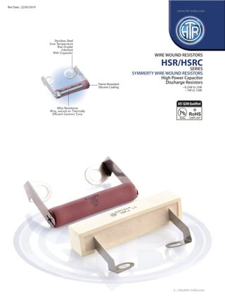
- 1. Stainless Steel (Low Temperature Rise Grade) Interface With Capacitor Alloy Resistance Wire, wound on Thermally Efficient Ceramic Core Flame Retardant Silicone Coating WIRE WOUND RESISTORS HSR/HSRC SERIES SYMMERTY WIRE WOUND RESISTORS High Power Capacitor Discharge Resistors • 8.25W to 25W • 10K to 120K e : info@htr-india.com www.htr-india.com Rev Date : 22/05/2019 AEC-Q200Qualified
- 2. PHYSICAL CONFIGURATION (Coated Style) - HSR Series HTR TYPE POWER RATING D ±1.0 P ±1.0 DIMENSIONS (mm) RESISTANCE RANGE TYPICAL WEIGHT PER PC (gms) min max P1 (max) * Resistance value lower than the above are possible on request at 70°C at 25°C TEMP. AT FULL POWER ON BODY T(a) & ON INTERFACE WITH CAPACITOR T(b) [AMB TEMP 30°C] SR8 8.25W 10W 9.65 22.30 38.0 260°C 57°C 10K 75K 8.0 SR11 11W 13W 9.65 31.85 49.0 264°C 59°C 10K 110K 8.75 SR20 20W 25W 9.65 48.85 66.0 300°C 65°C 10K 120K 13.00 HTR TYPE POWER RATING RESISTANCE RANGE TYPICAL WEIGHT PER PC (gms)min max at 70°C at 25°C TEMPERATURE AT FULL POWER ON BODY T(a) & ON INTERFACE WITH CAPACITOR T(b) [AMB TEMP 30°C] SRC11 11W 13W 258°C 50°C 10K 110K 27 SRC20 20W 22W 264 °C 52°C 10K 110K 27 SRC25 25W 27W 278°C 52°C 10K 110K 27 PHYSICAL CONFIGURATION (Ceramic Encased Style) - HSRC Series T(b)T(a) T(b)T(a) WIRE WOUND RESISTORS HSR/ HSRC e : info@htr-india.com www.htr-india.com 15.50 MM (MAX) 66.0 MM (MAX) 14.75 MM (MAX) Rev Date : 22/05/2019
- 3. ELECTRICAL & ENVIRONMENTAL CHARACTERISTICS / DATA Power Rating (Rated Ambient Temperature) Full Power dissipation at 70°C and linearly derated to zero at 350°C (Refer Derating Curve above) Resistance Tolerances Available ±10% (K); ±5% (J); ±3% (H); ±2% (G); ±1% (F) Temperature Range -55°C to +350°C with suitable derating as per derating curve Voltage Rating / Limiting Voltage / Max. Working Voltage V= PxR Voltage Proof / Dielectric Withstanding Voltage ∆R ± [1% + R05] (based on limiting voltage x 2 or 500V whichever is applicable) Temperature Co-efficient of Resistance ± 90 or ± 30 ppm/°C depending on wire selected Short Time Overload (10 x Rated Power for 5 secs) ∆R ± [2% + R05] Insulation Resistance (Test Method no. 302 of MIL 202F) >1000M (Dry) >100M (Wet) Endurance - Load life ∆R ± [≤5% + R05] (70°C with limiting voltage - 1.5 hours on / 0.5 hours off for 1000 hours) Solvent Resistance (IPA for 60 secs ± 10 secs) No effect on coating / marking or case filling Vibration Test (As per IEC 60571-1) No effect PARAMETER/PERFORMANCE TEST & TEST METHOD PERFORMANCE REQUIREMENTS For RoHS version - SR11* / SRC25* TYPICAL APPLICATIONS • These high power wire wound resistors have low temperature rise stainless steel mounting lugs fitted to them at a pitch which is ideally suitable to mount on capacitors and are used mainly for voltage balancing of aluminium electrolytic capacitors connected in series. • These resistors are also used in safety applications; wherein they have been found suitable for capacitor voltage discharge applications in high voltage circuits. Note: The ceramic cases used may be steatite ceramic or corderite ceramic or high alumina ceramic. Hence, the ceramic cases may be offwhite or variations of brown and variations of grey; colours which are inherent to these ceramic materials. ORDERING INFORMATION Series Type Packing Resistance Value Tolerance HSR / SR8/SR8* Bulk SR8/SR8* HSRC SRC25/SRC25* Bulk SRC25/SRC25* 15K J WIRE WOUND RESISTORS HSR/ HSRC e : info@htr-india.com www.htr-india.com Rev Date : 22/05/2019