Download as PDF, PPTX
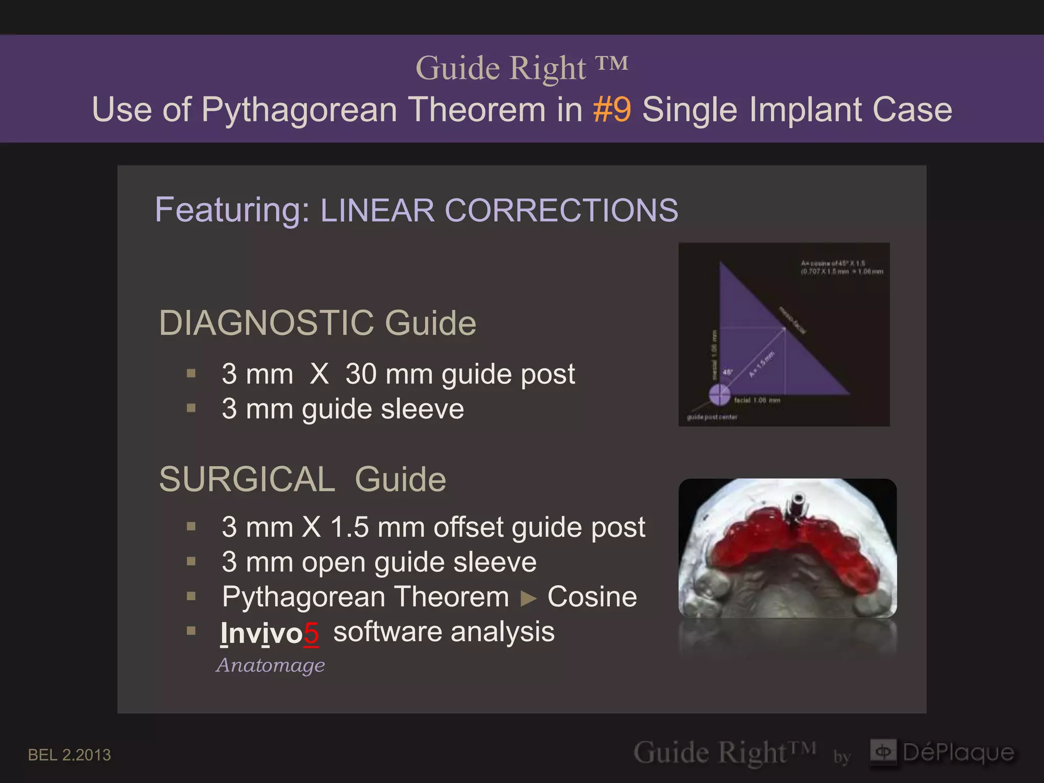
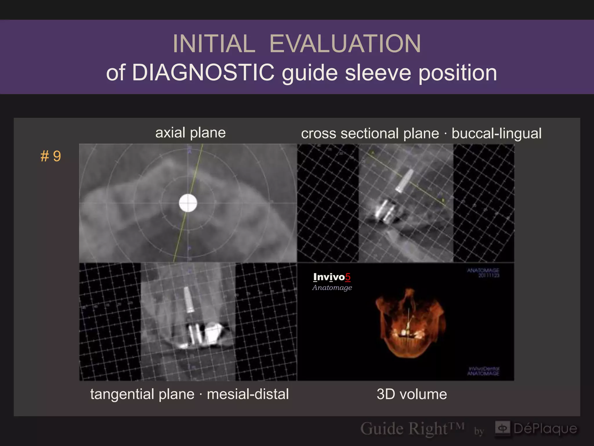
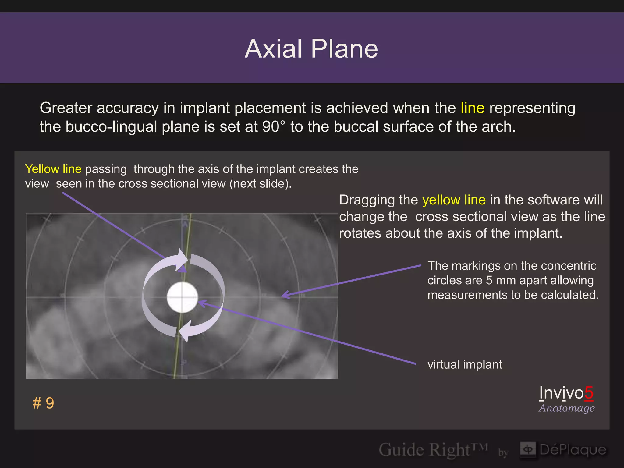
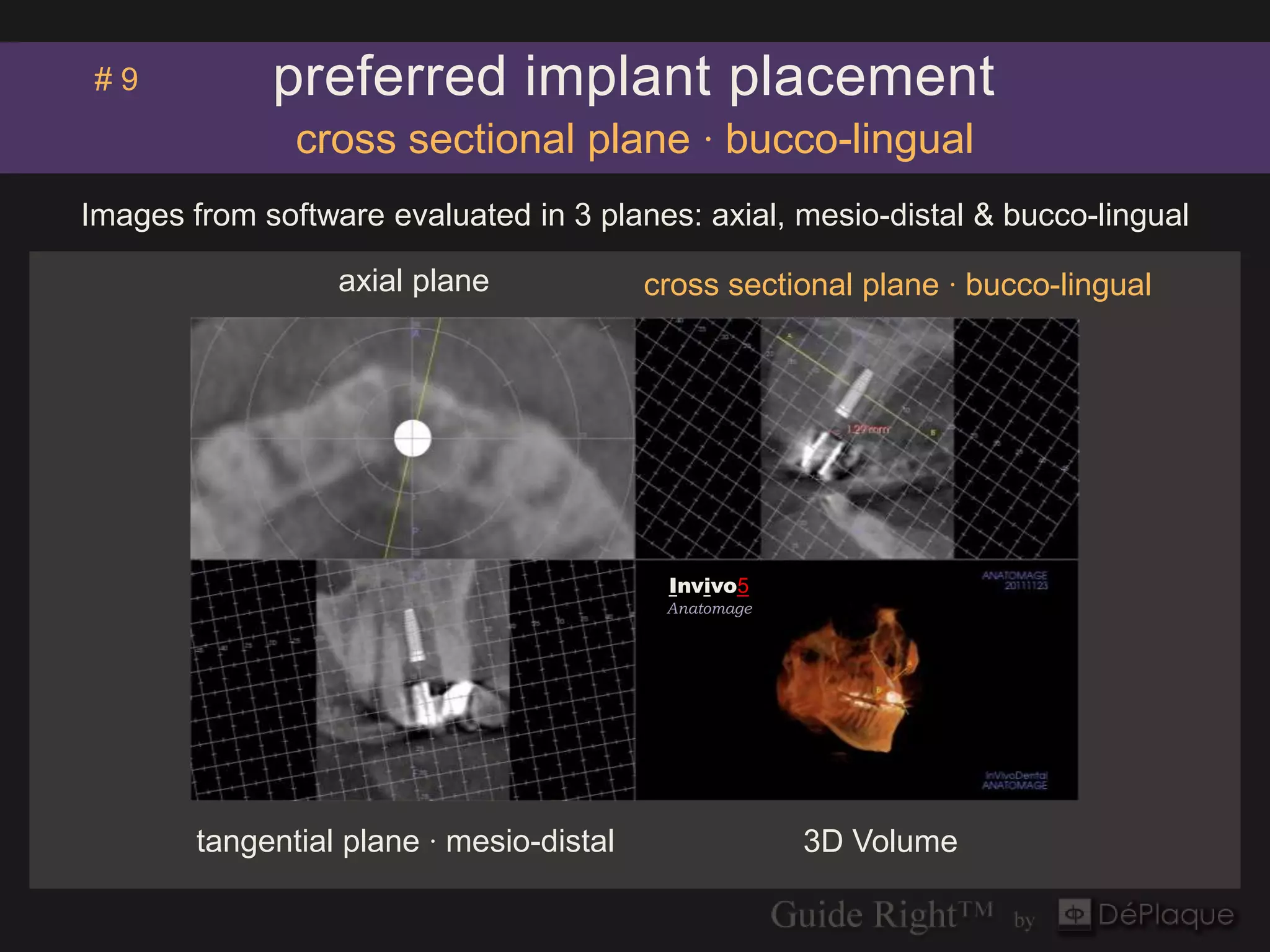
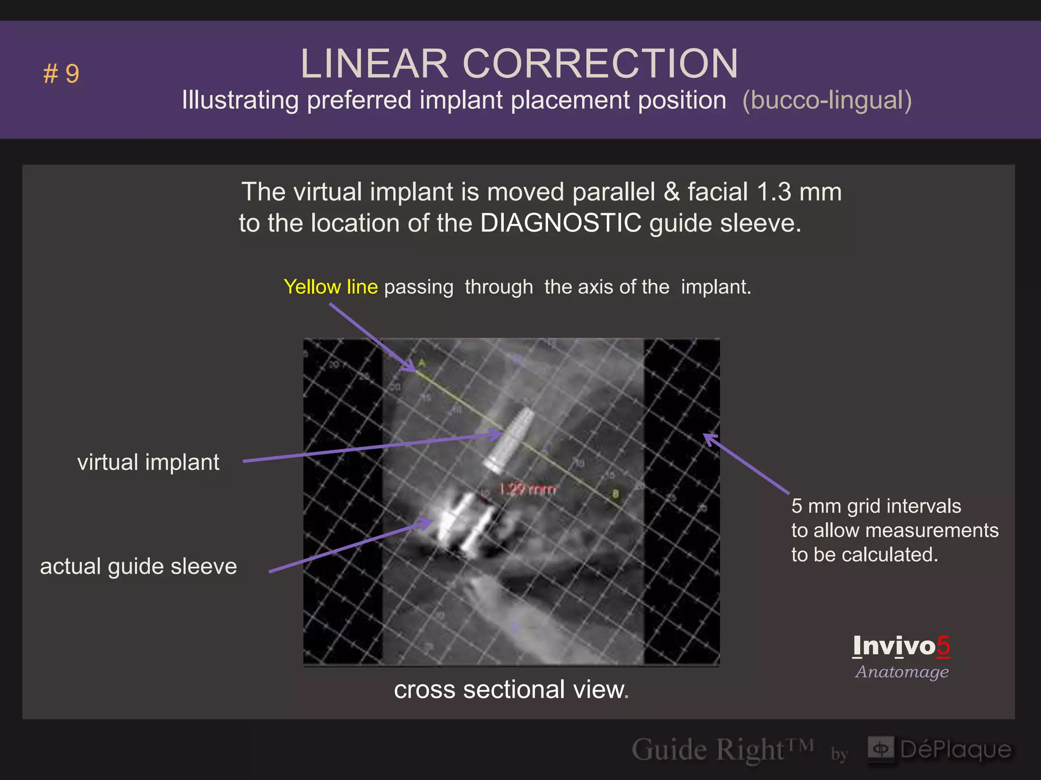
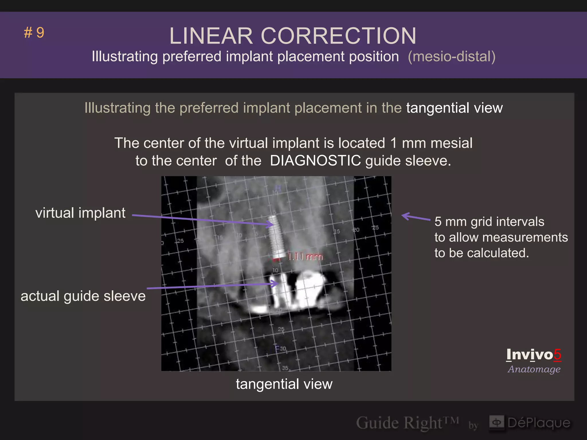
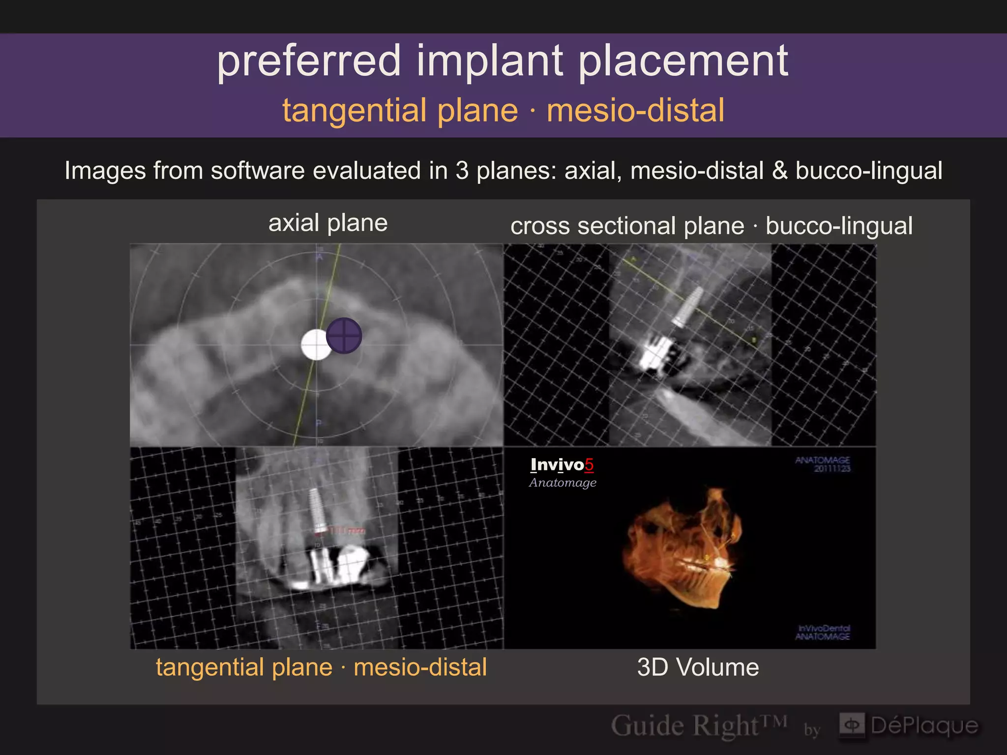
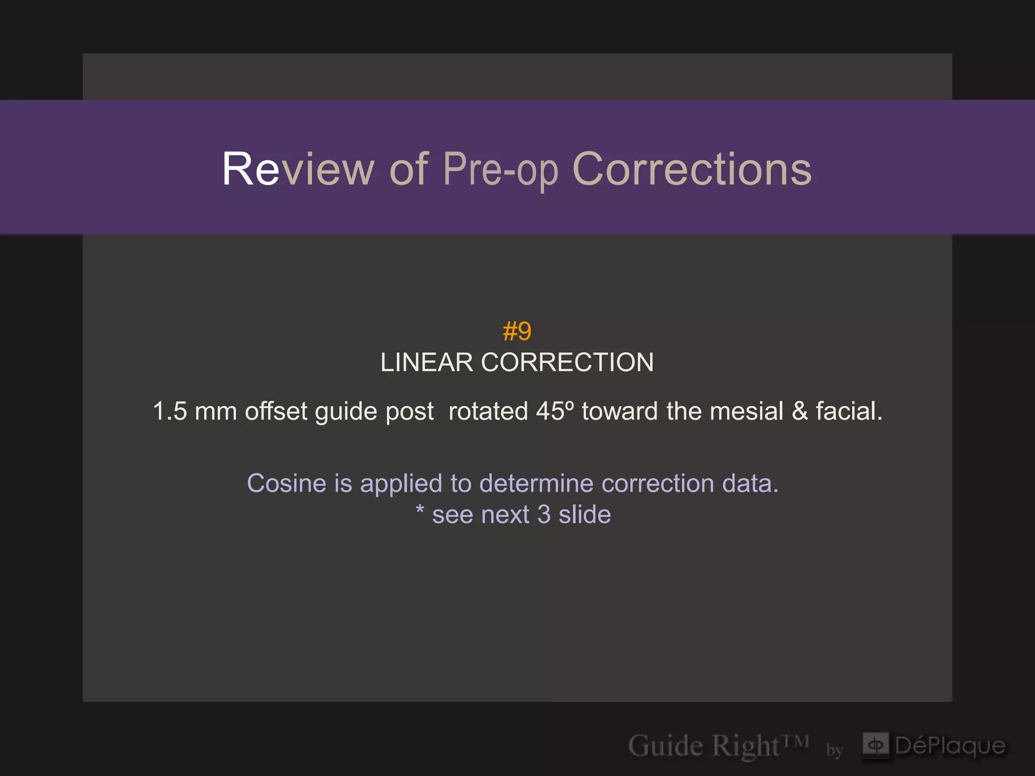

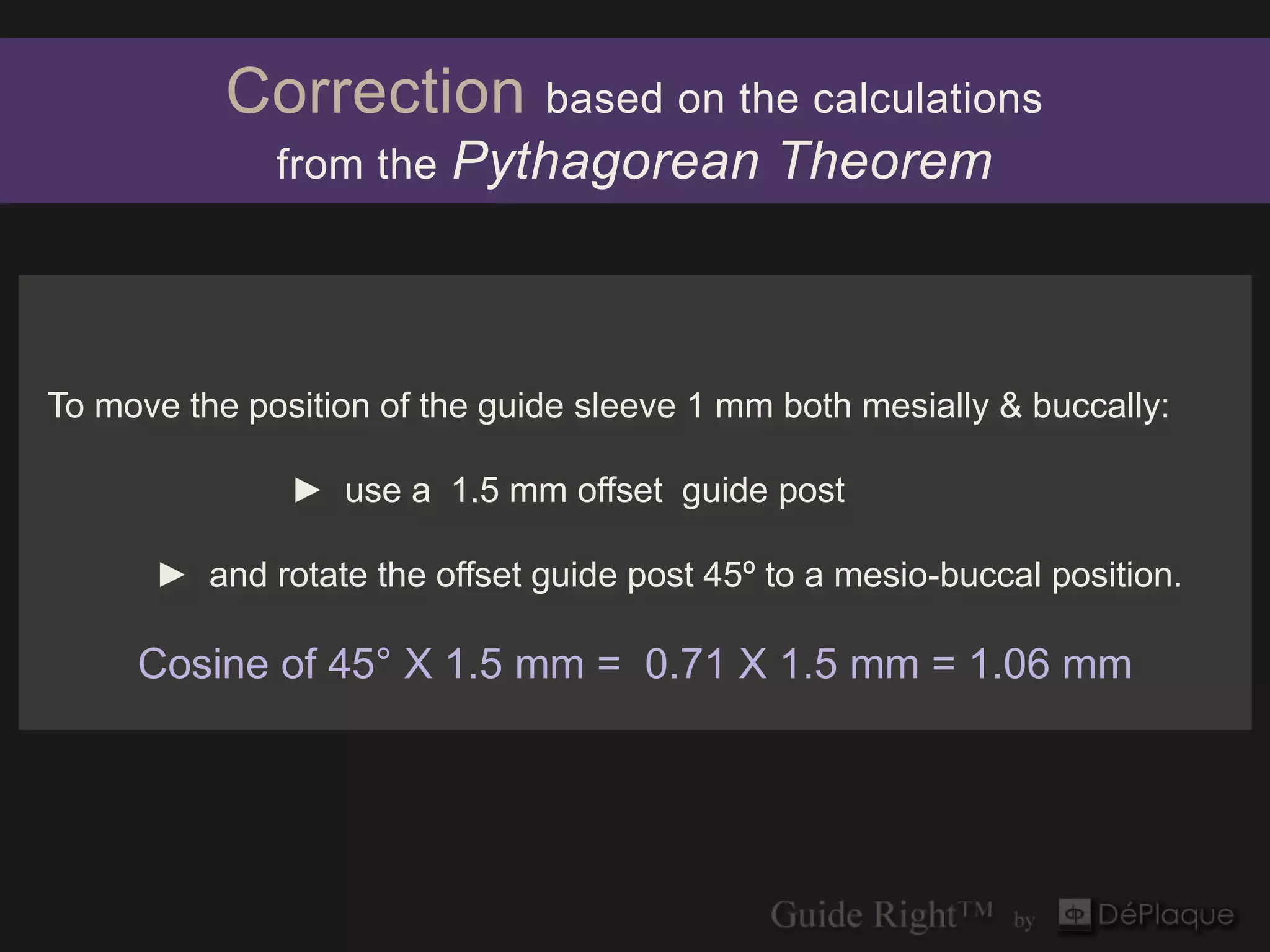
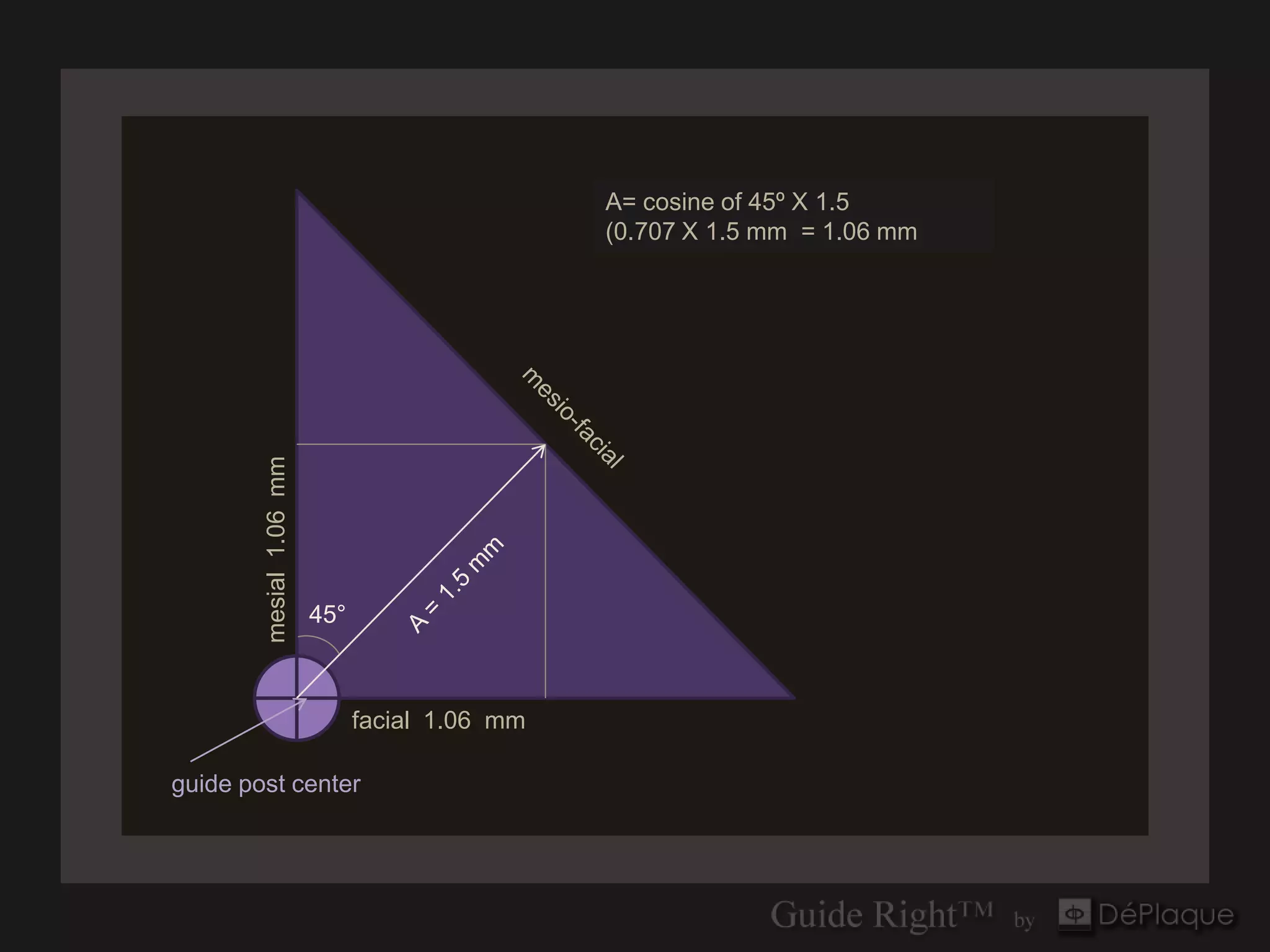
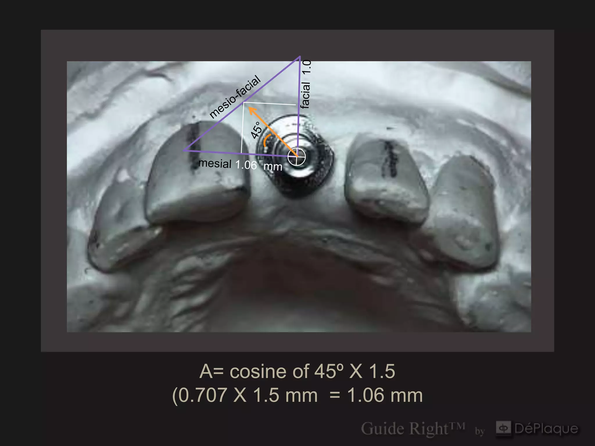


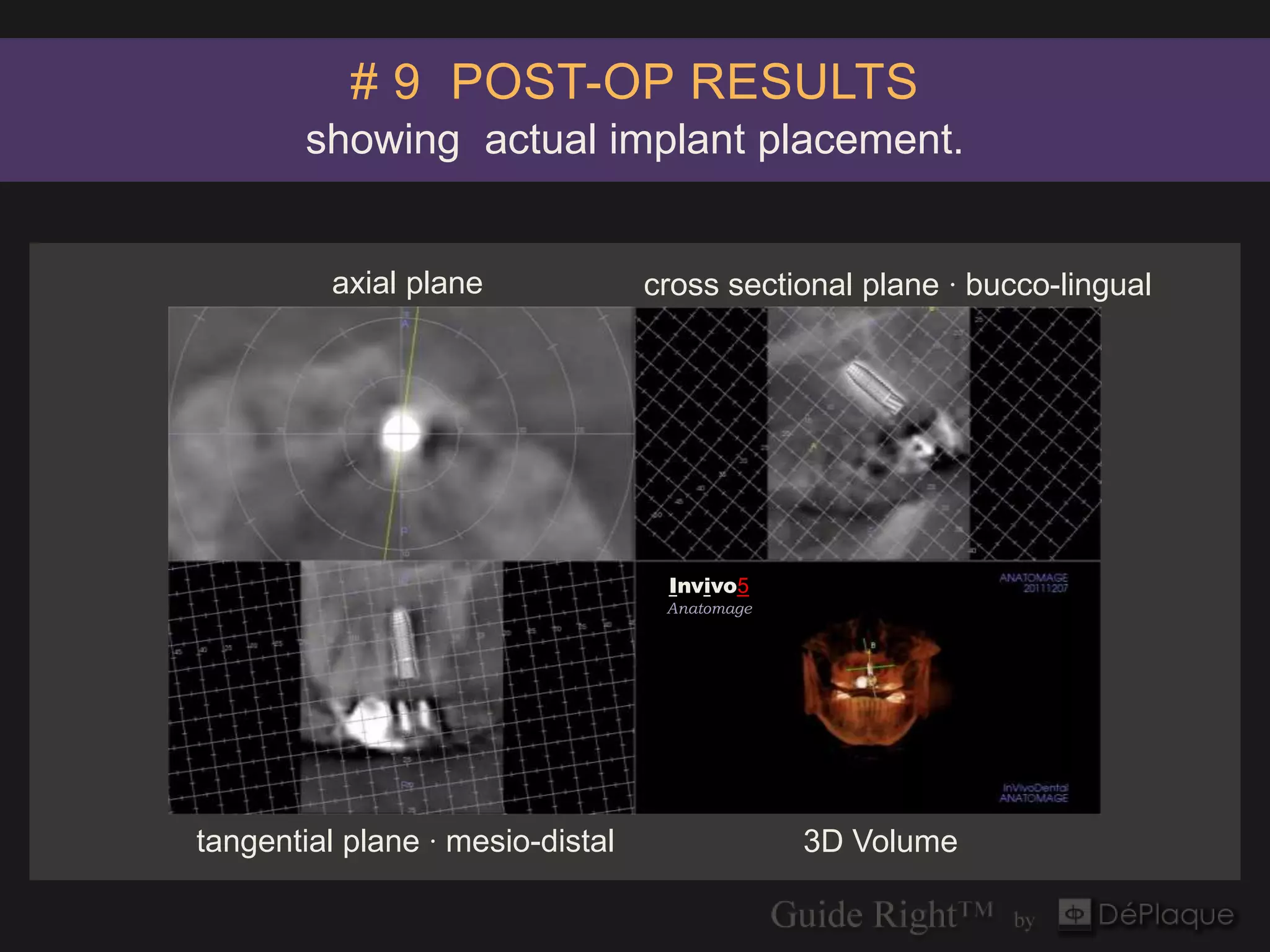
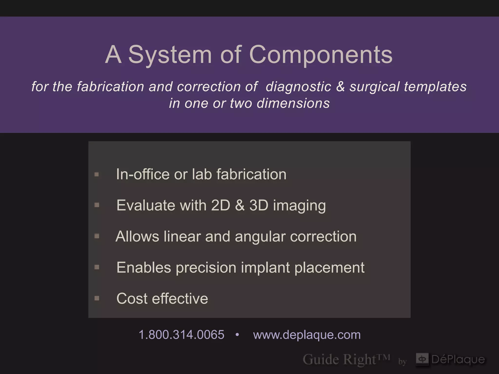

The document outlines the use of the Pythagorean theorem and specific surgical design principles in creating diagnostic and surgical guides for implant placement, particularly focusing on case #9. It details the materials used, the process of guide fabrication, and the importance of accurate positioning using software analysis to enhance the precision of implant placement. Additionally, it emphasizes the application of cosine calculations for corrective measures to ensure optimal outcomes during the surgical procedure.


