Download as PDF, PPTX
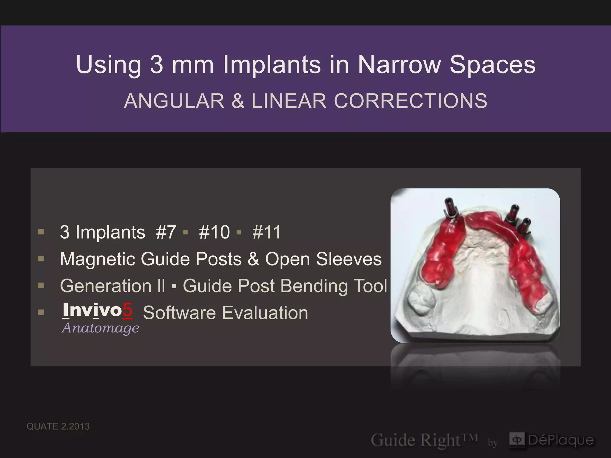
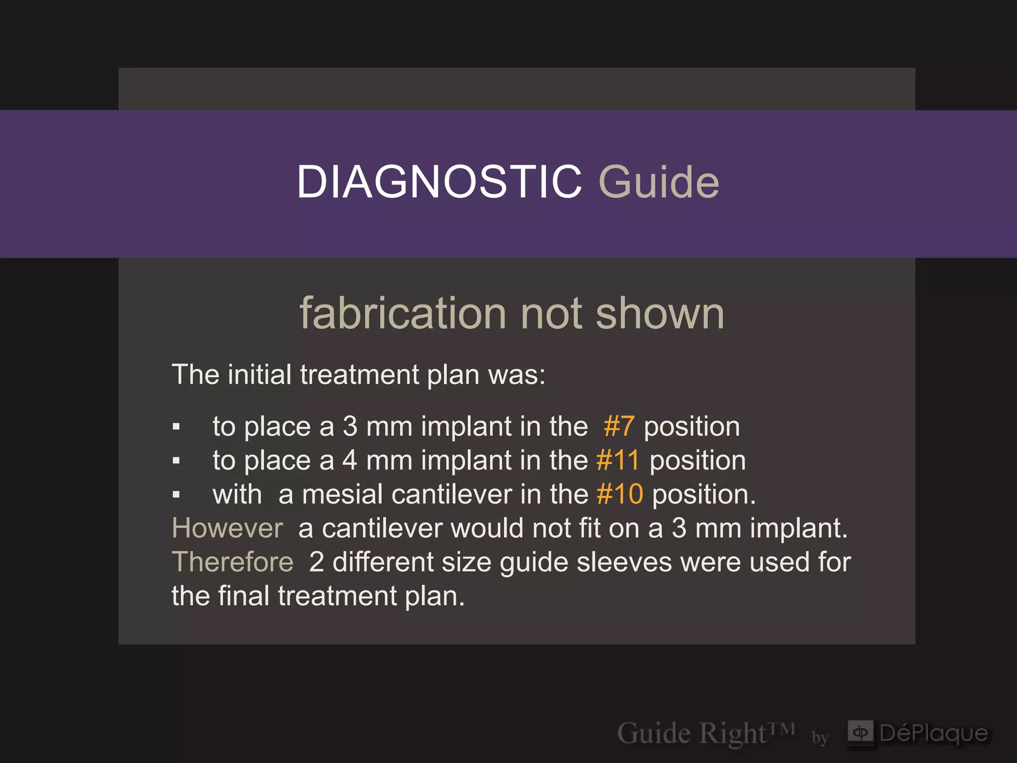
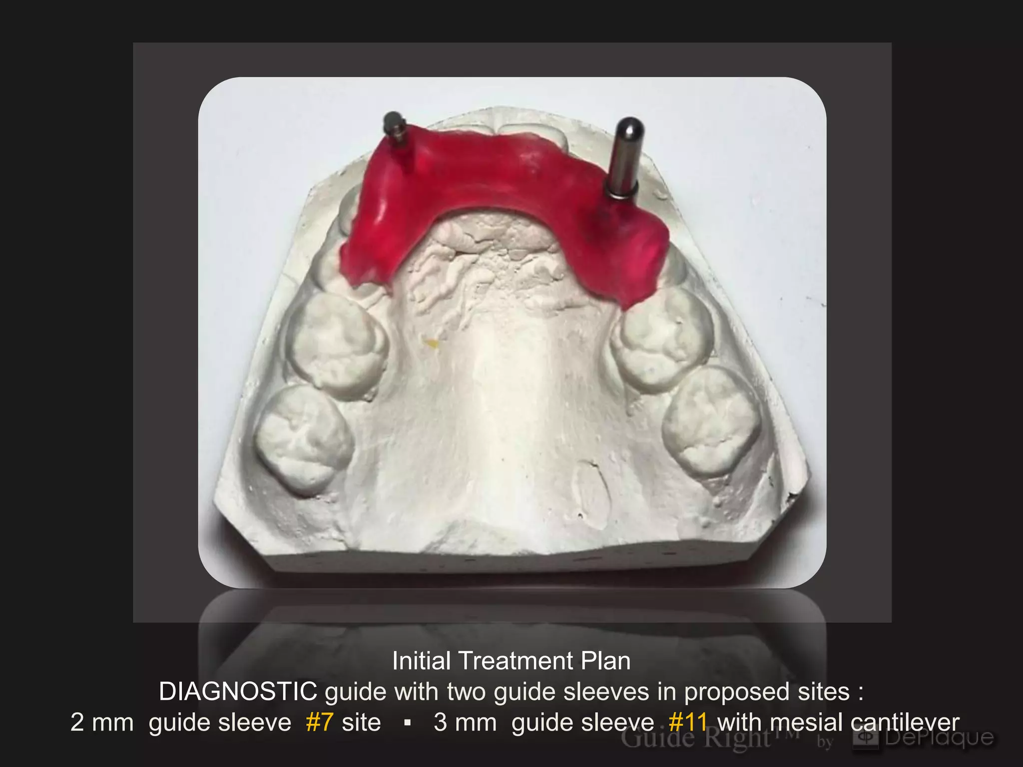
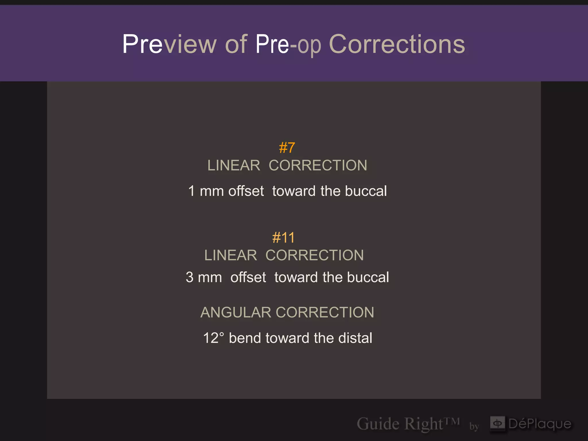
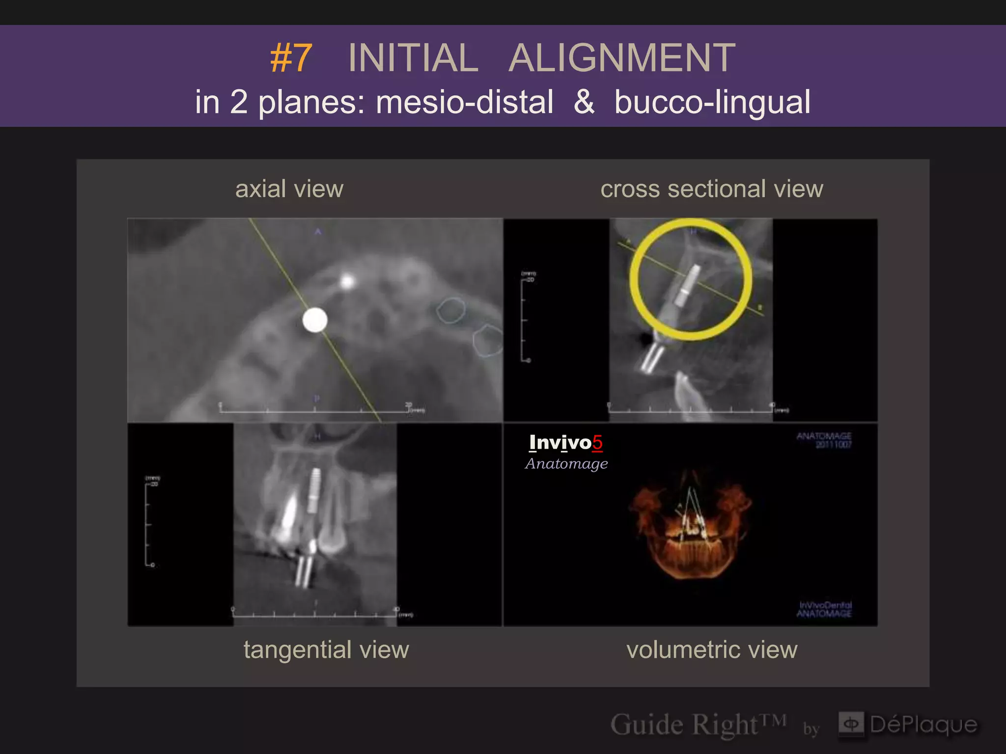
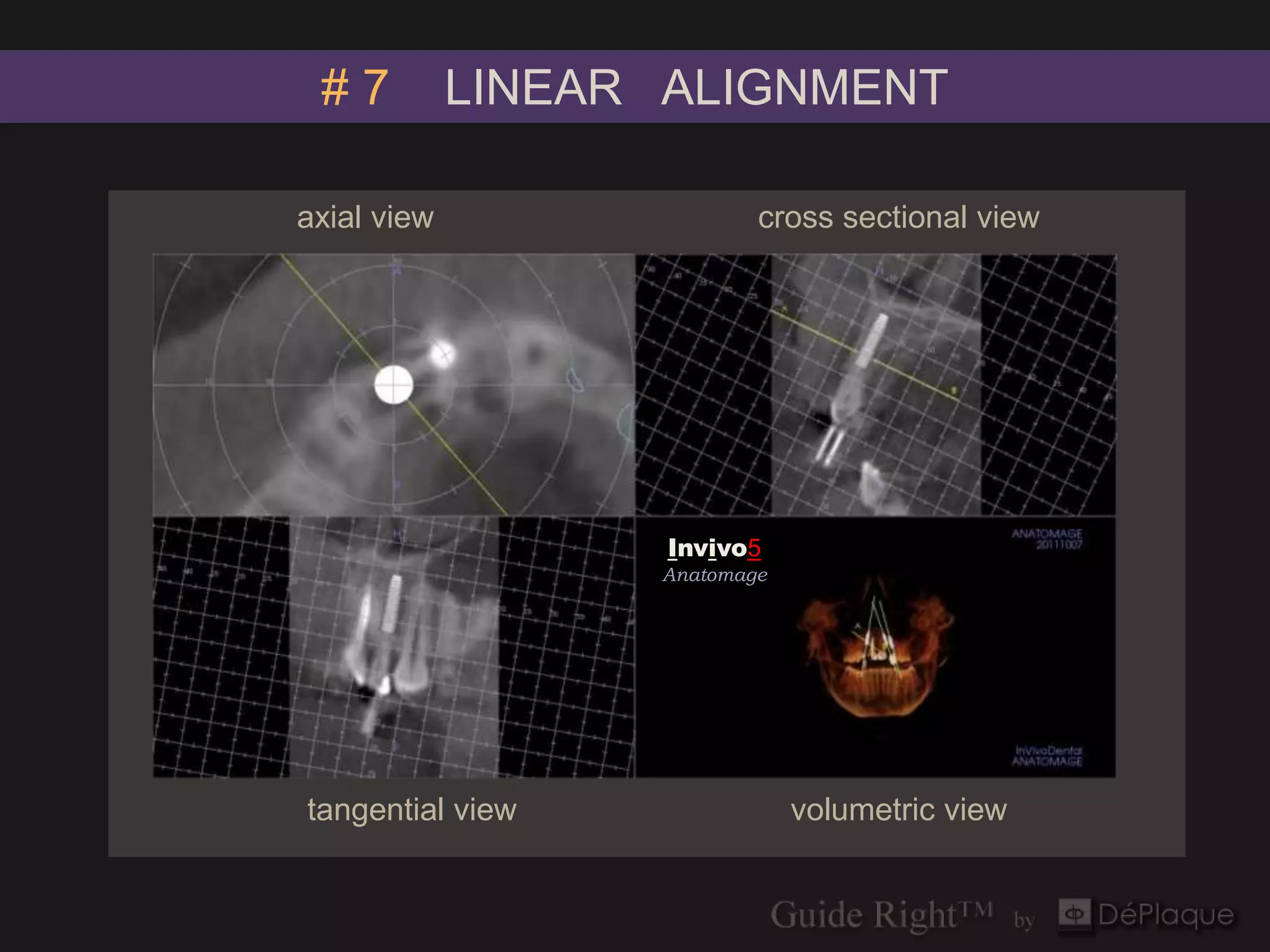
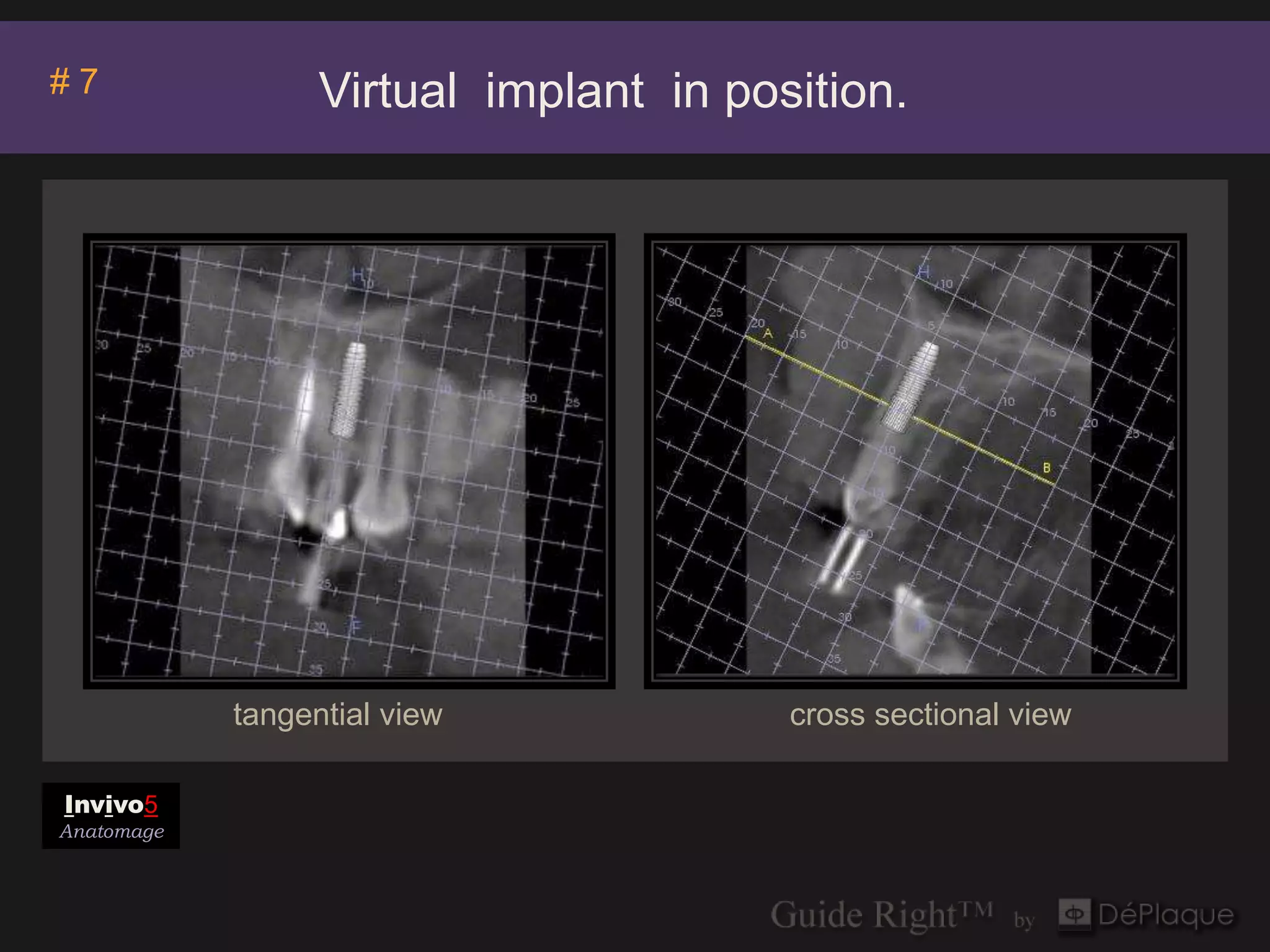
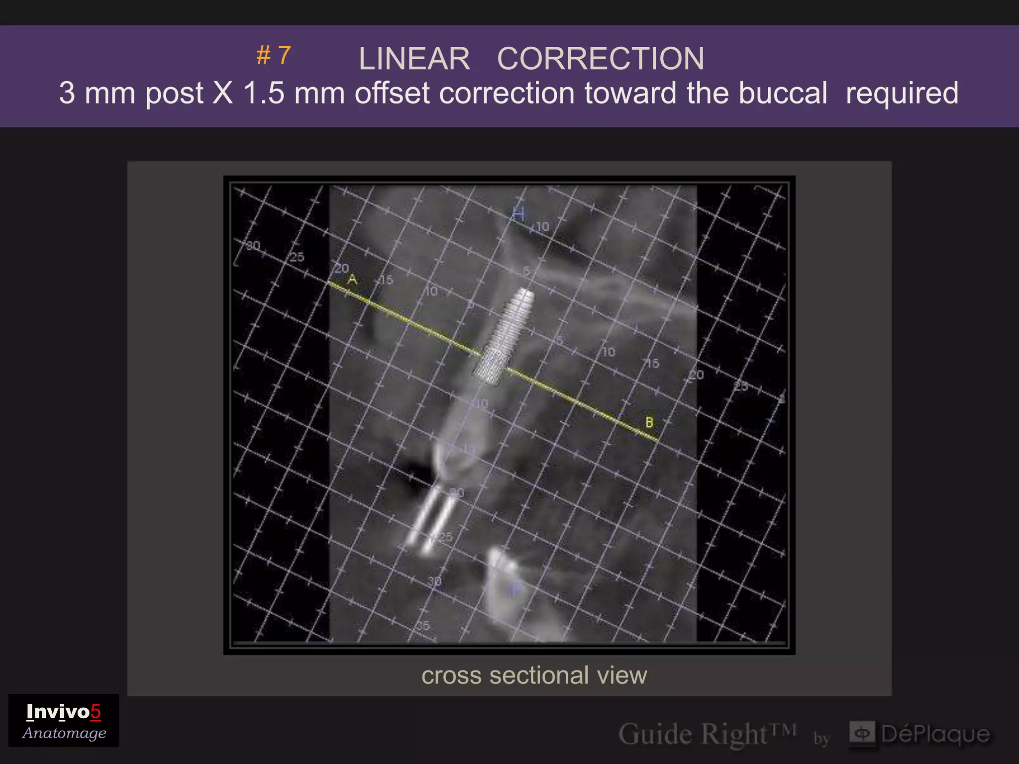
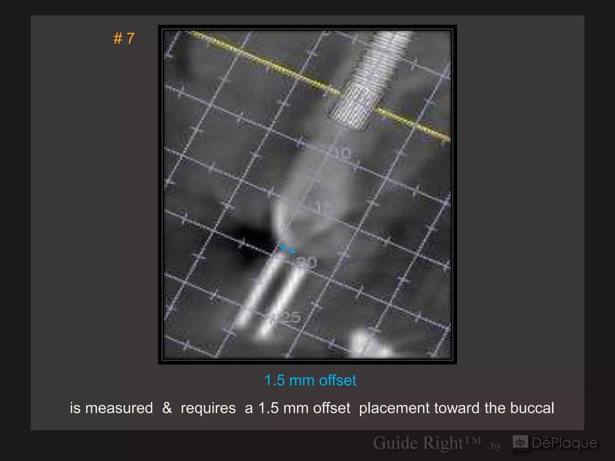
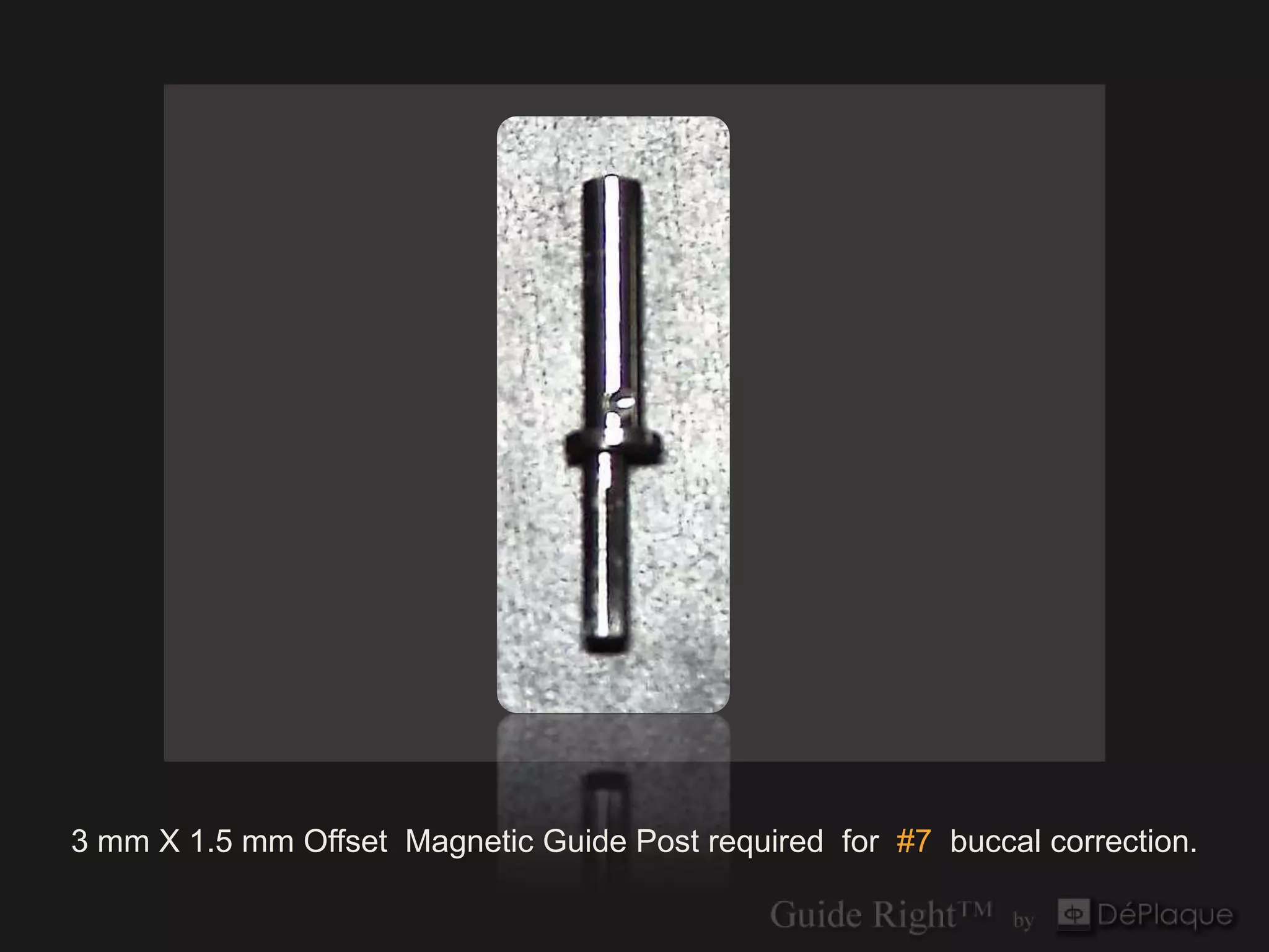
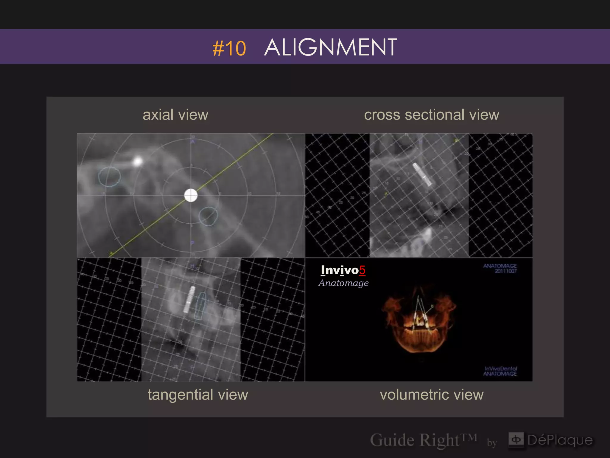
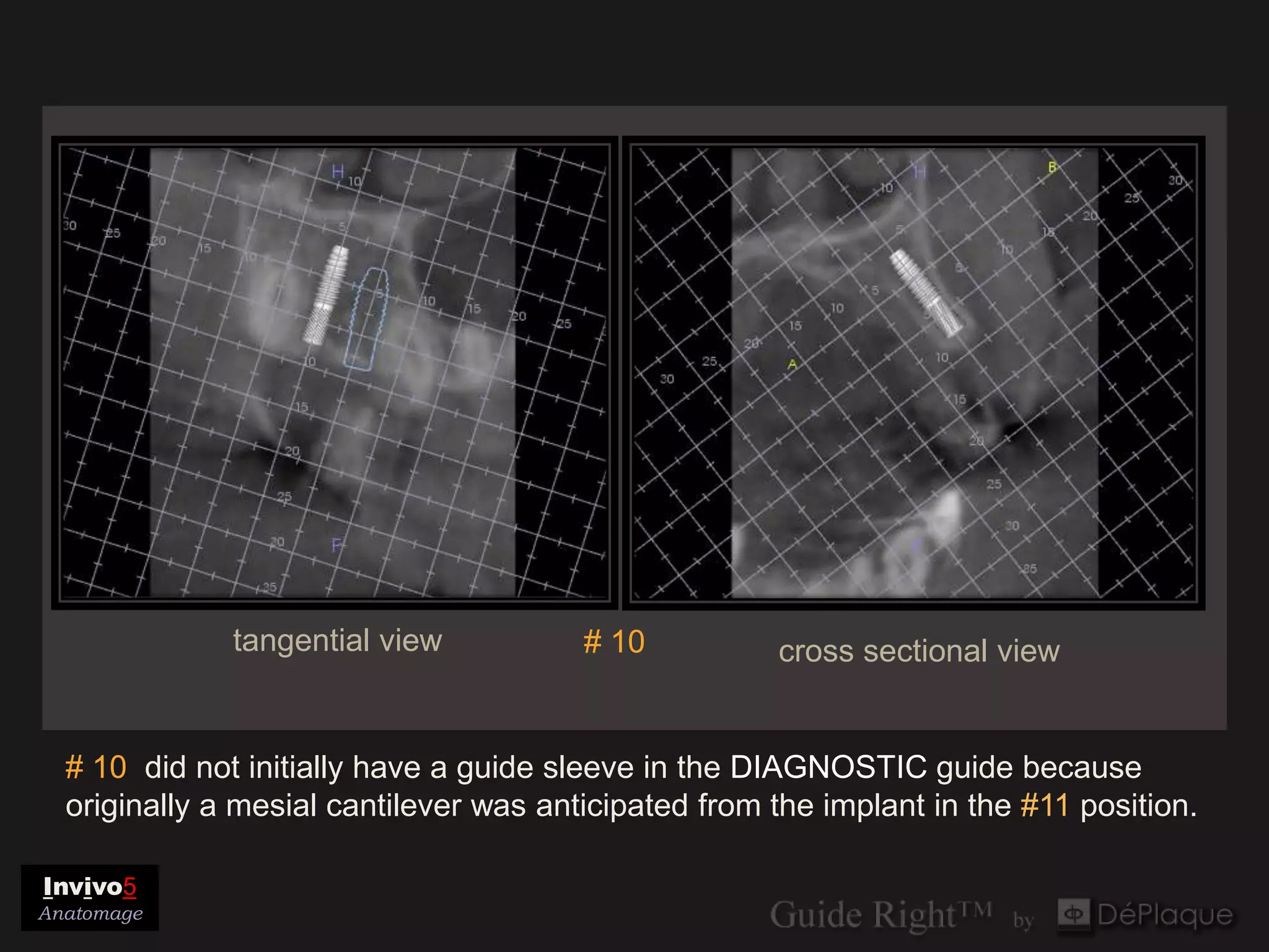
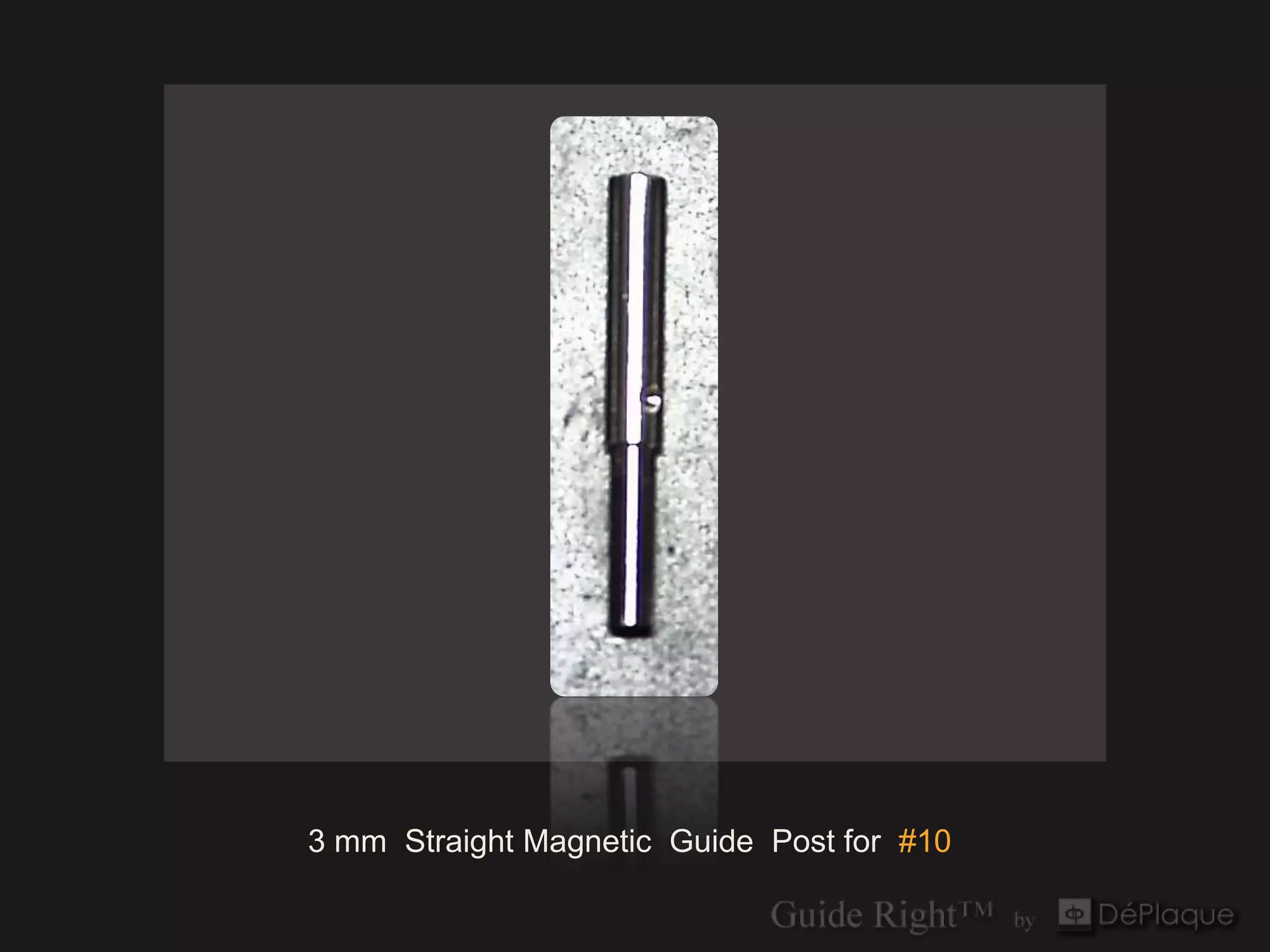
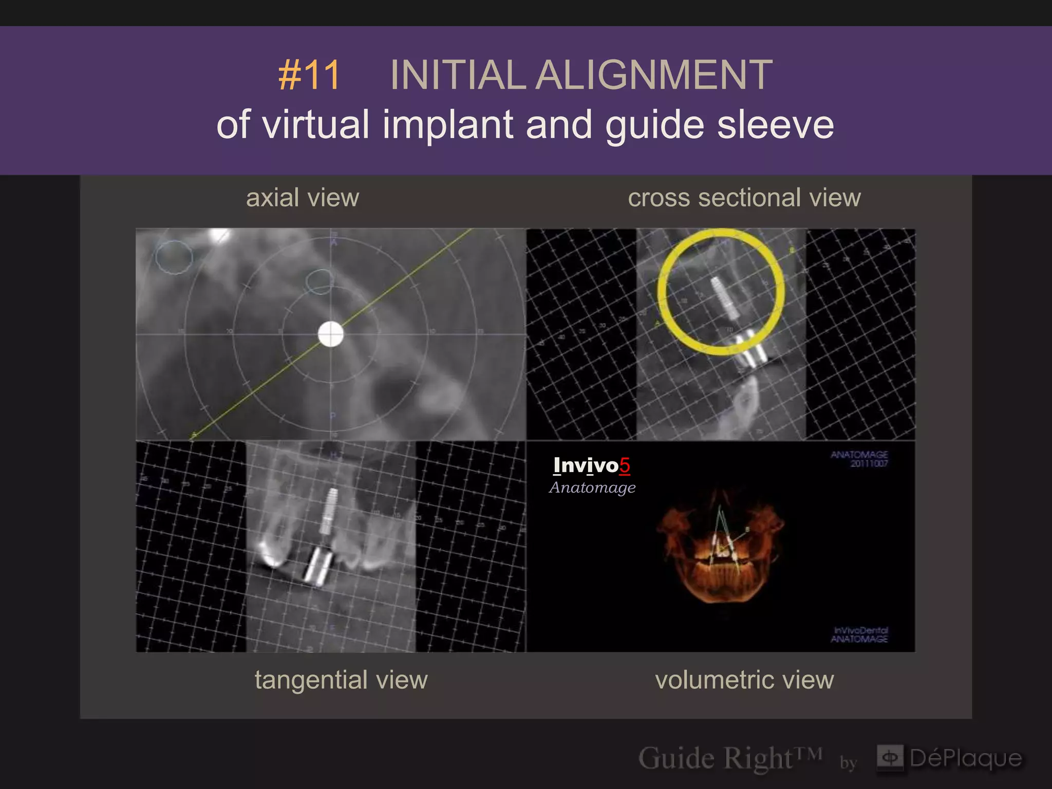
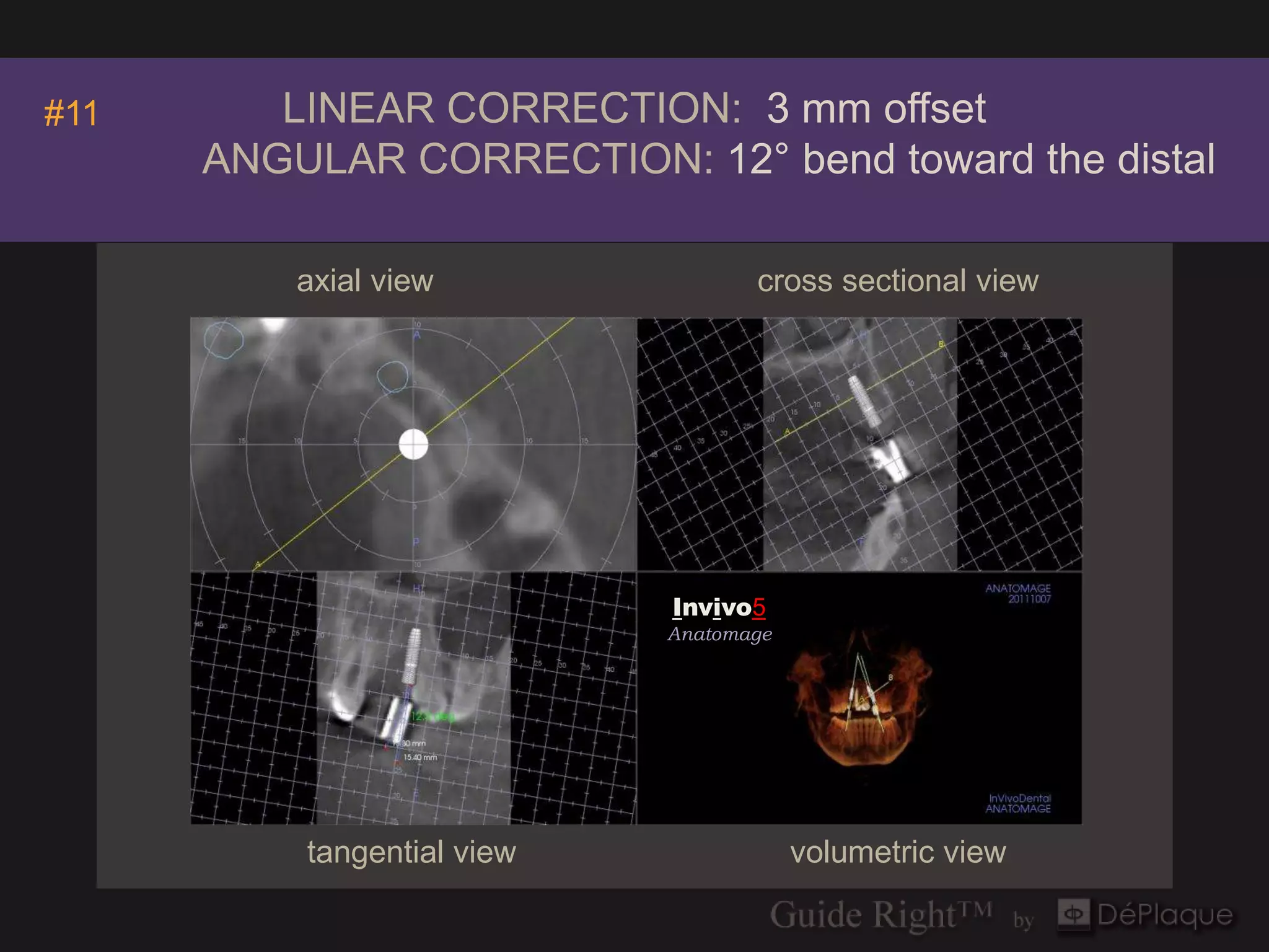
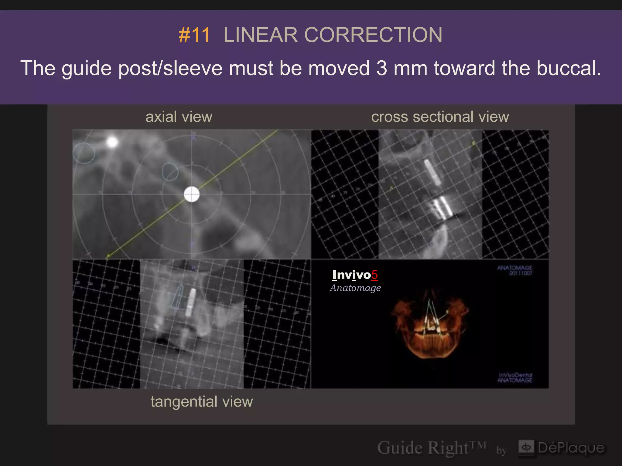
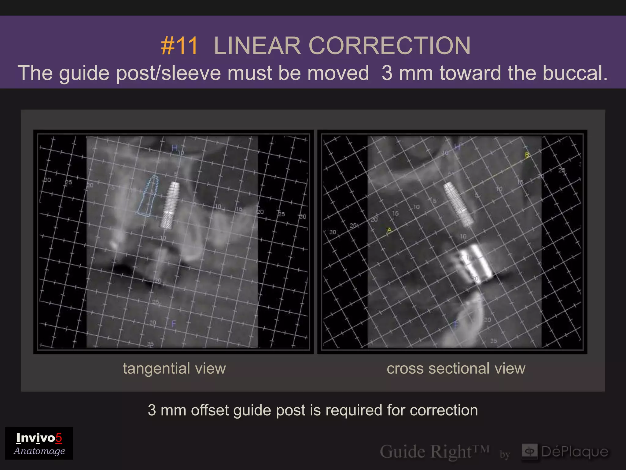
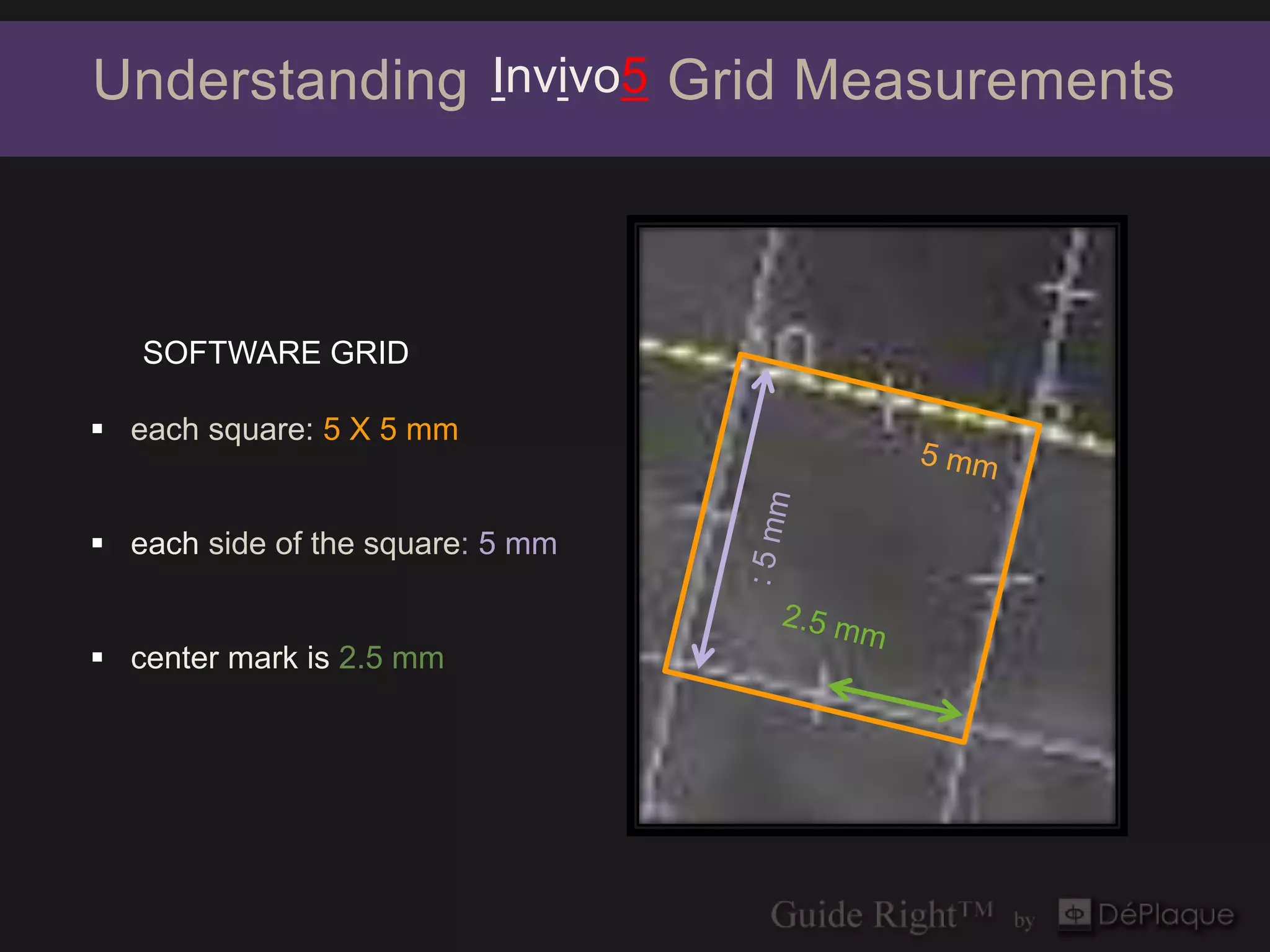
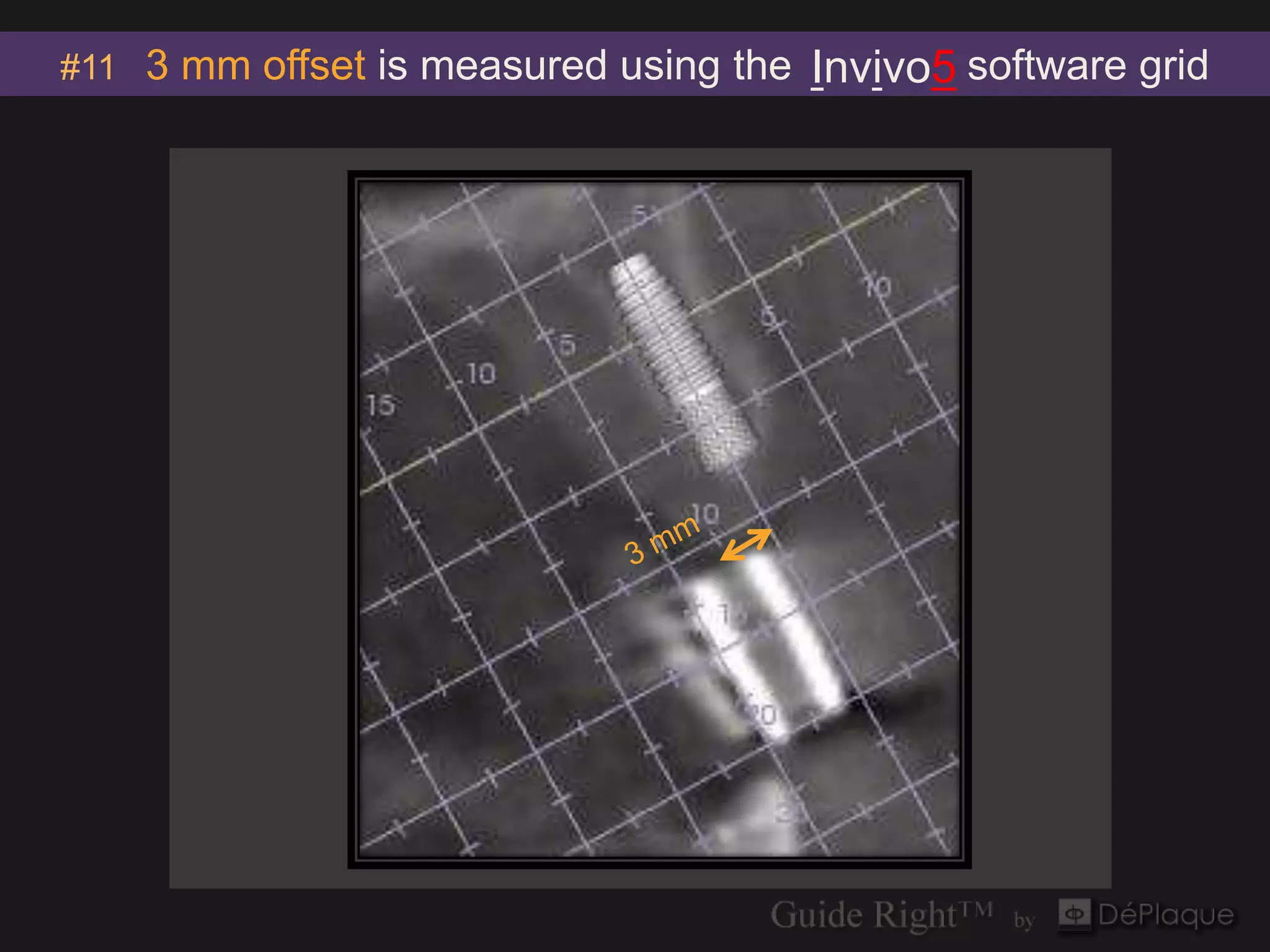
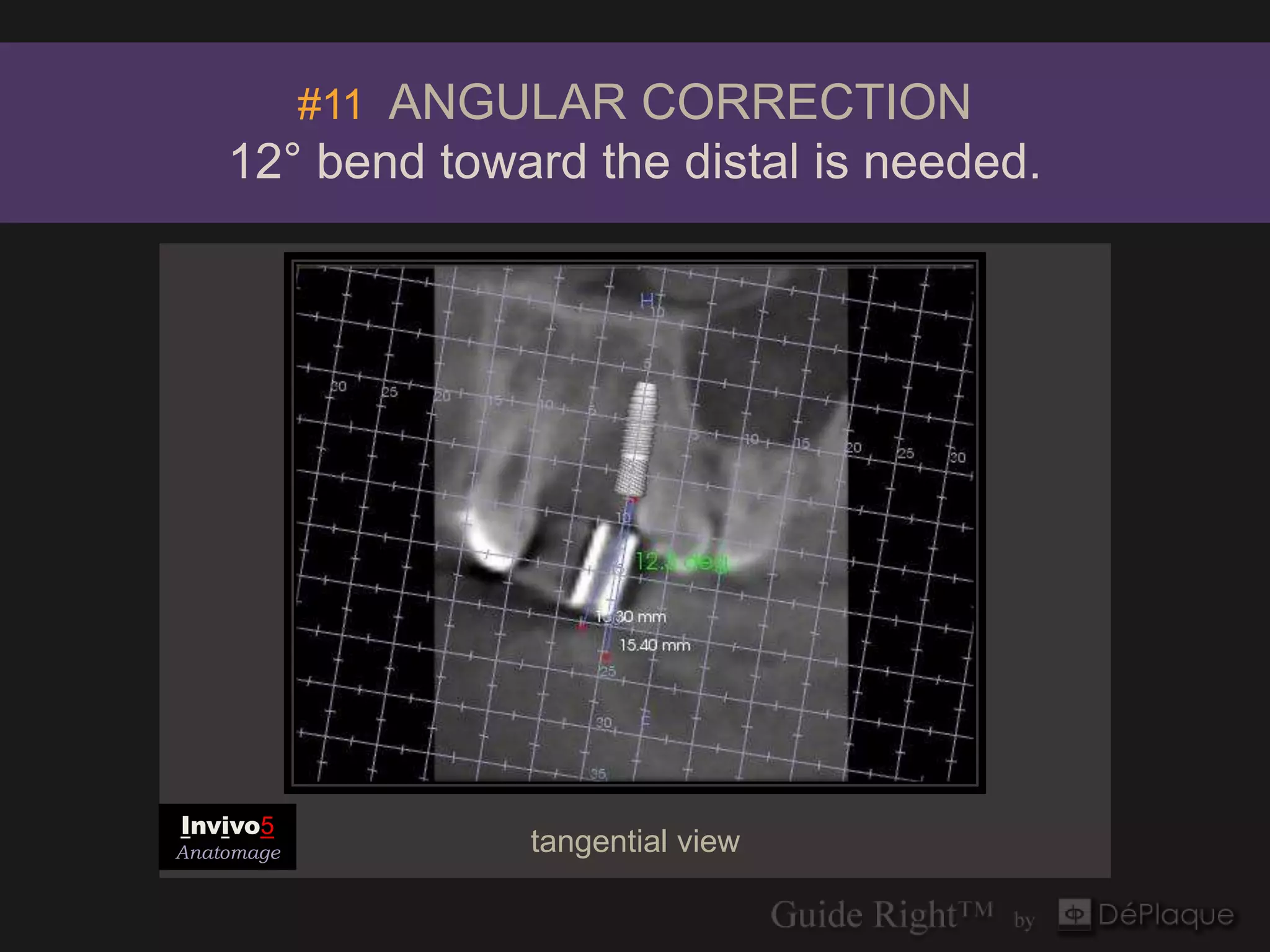
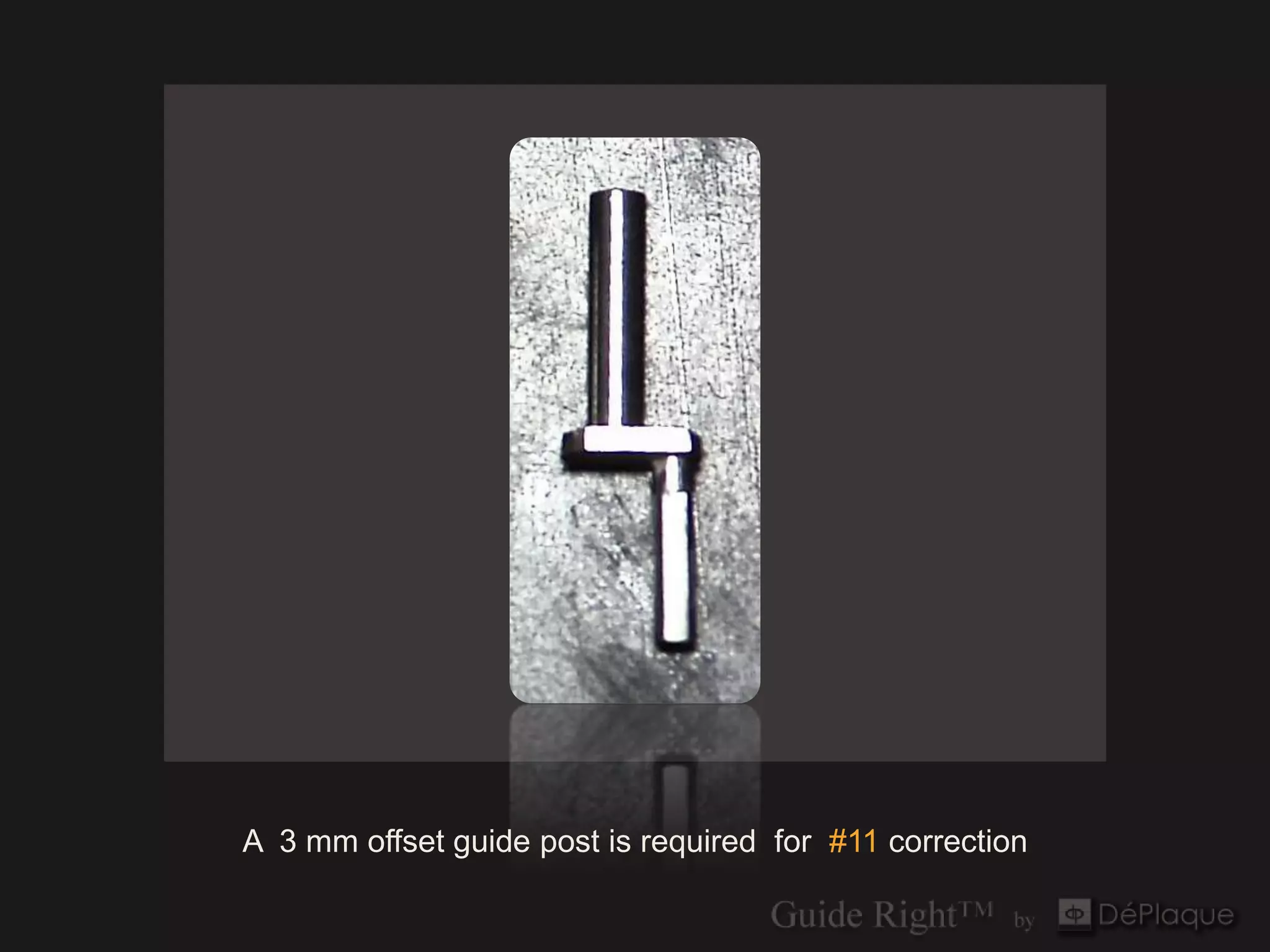
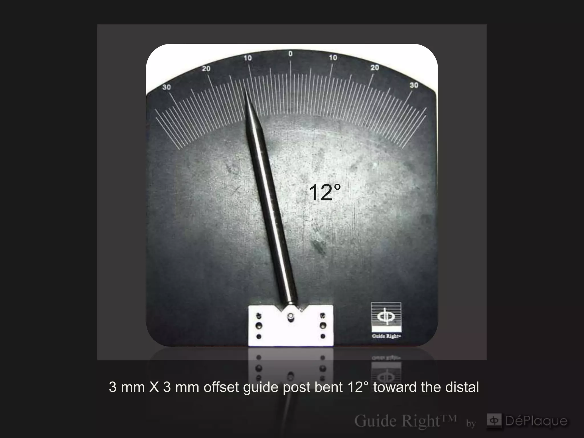
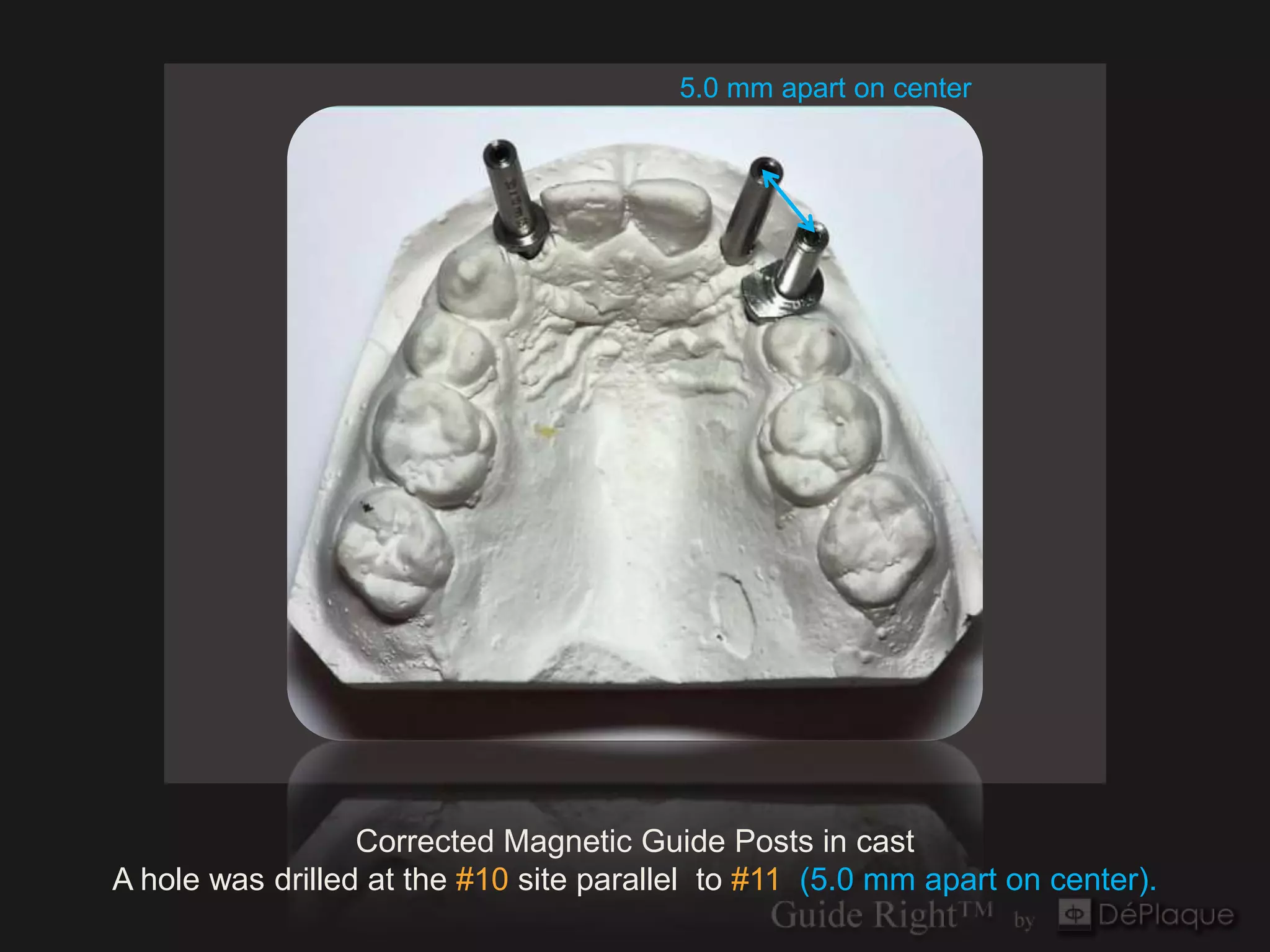
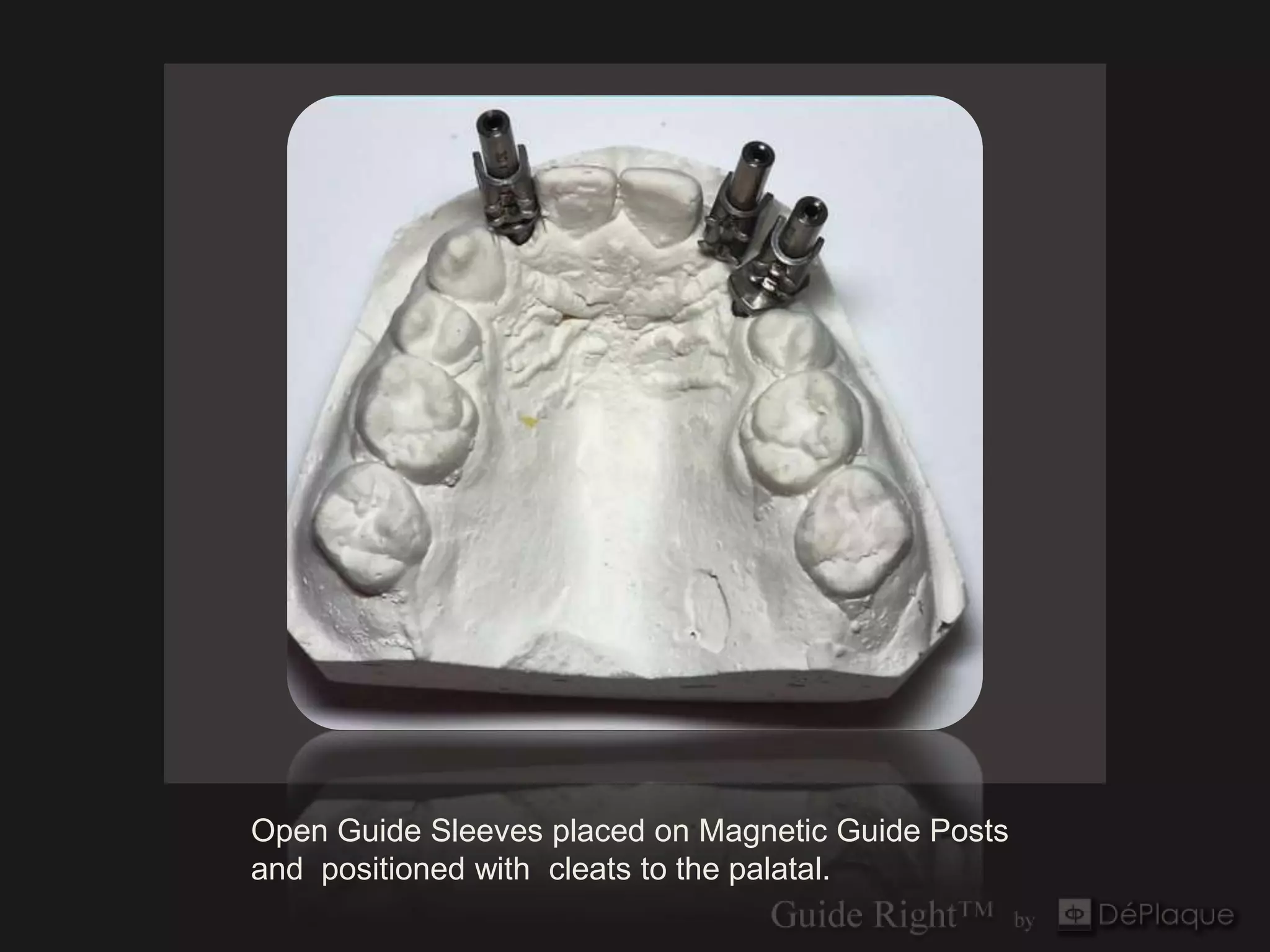
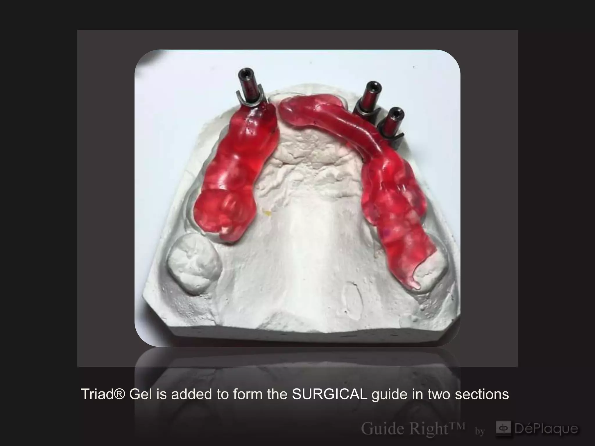
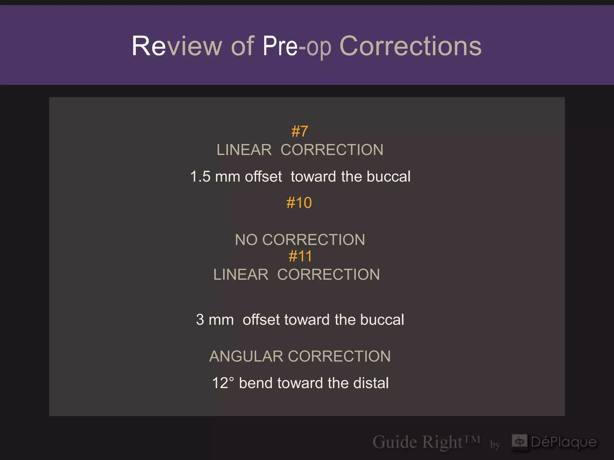
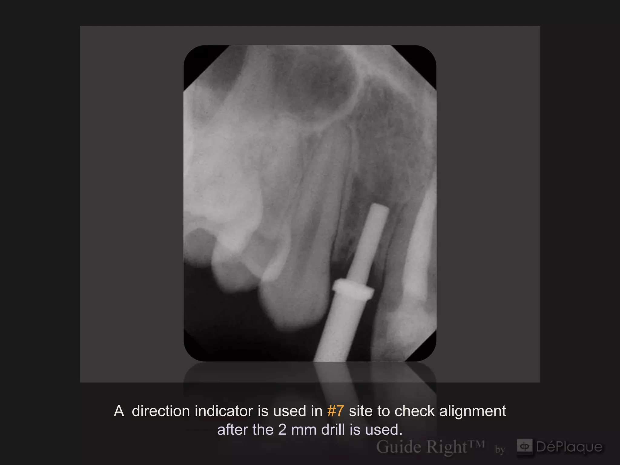
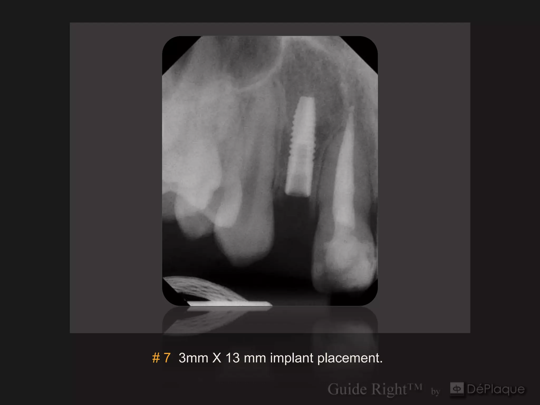
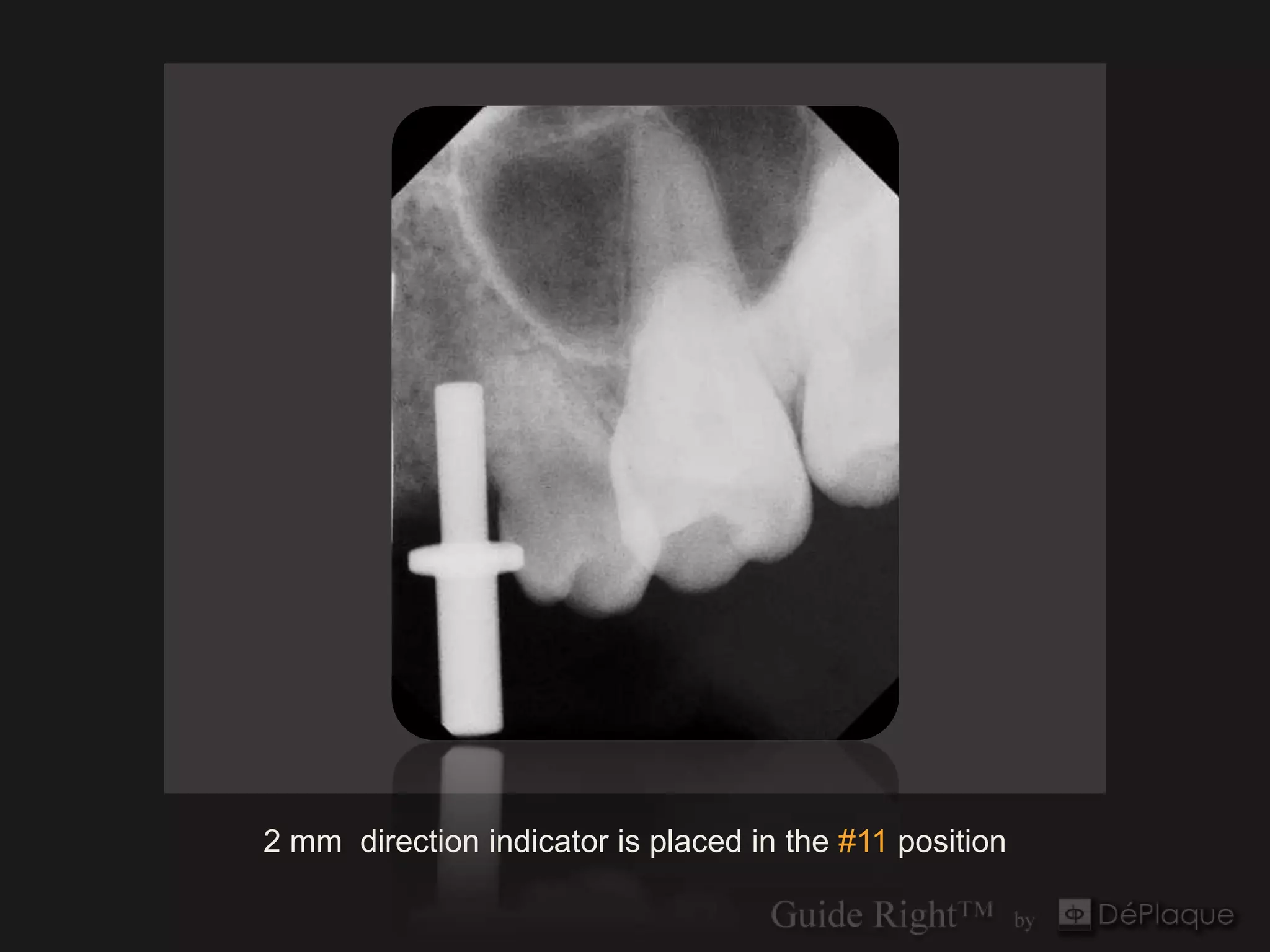
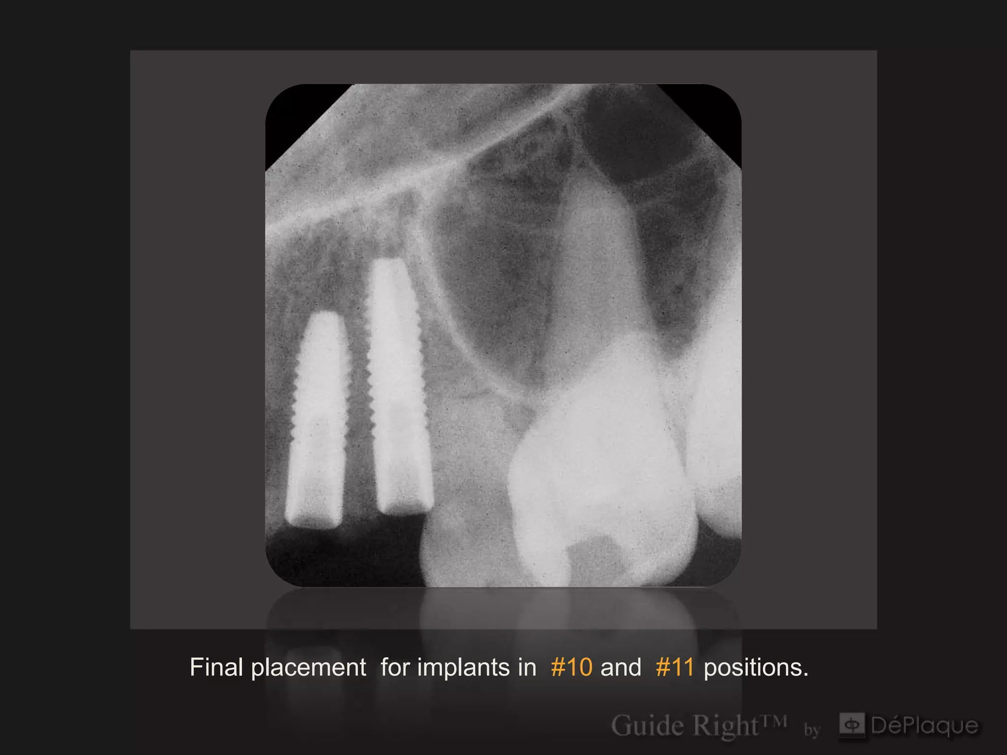
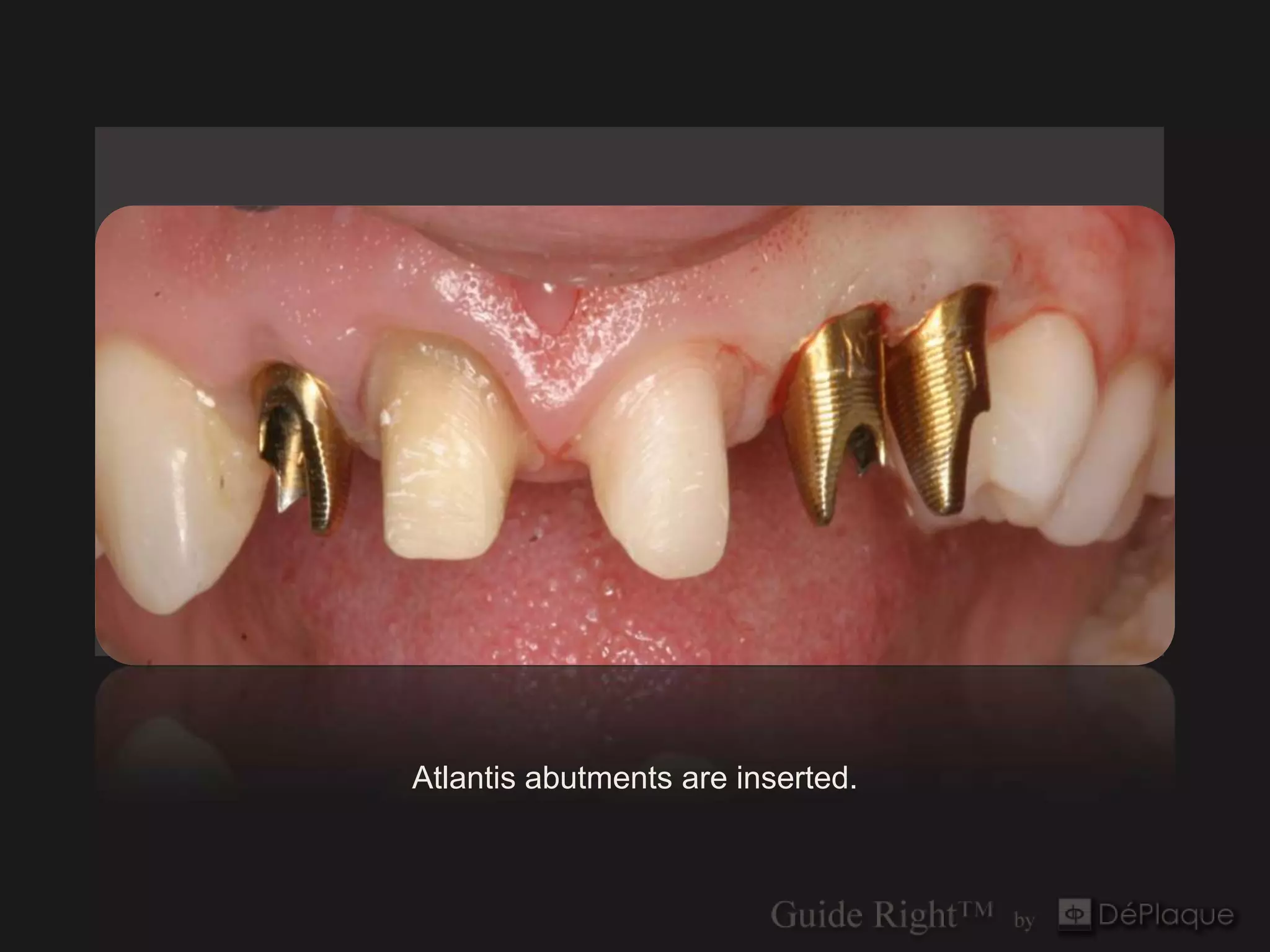
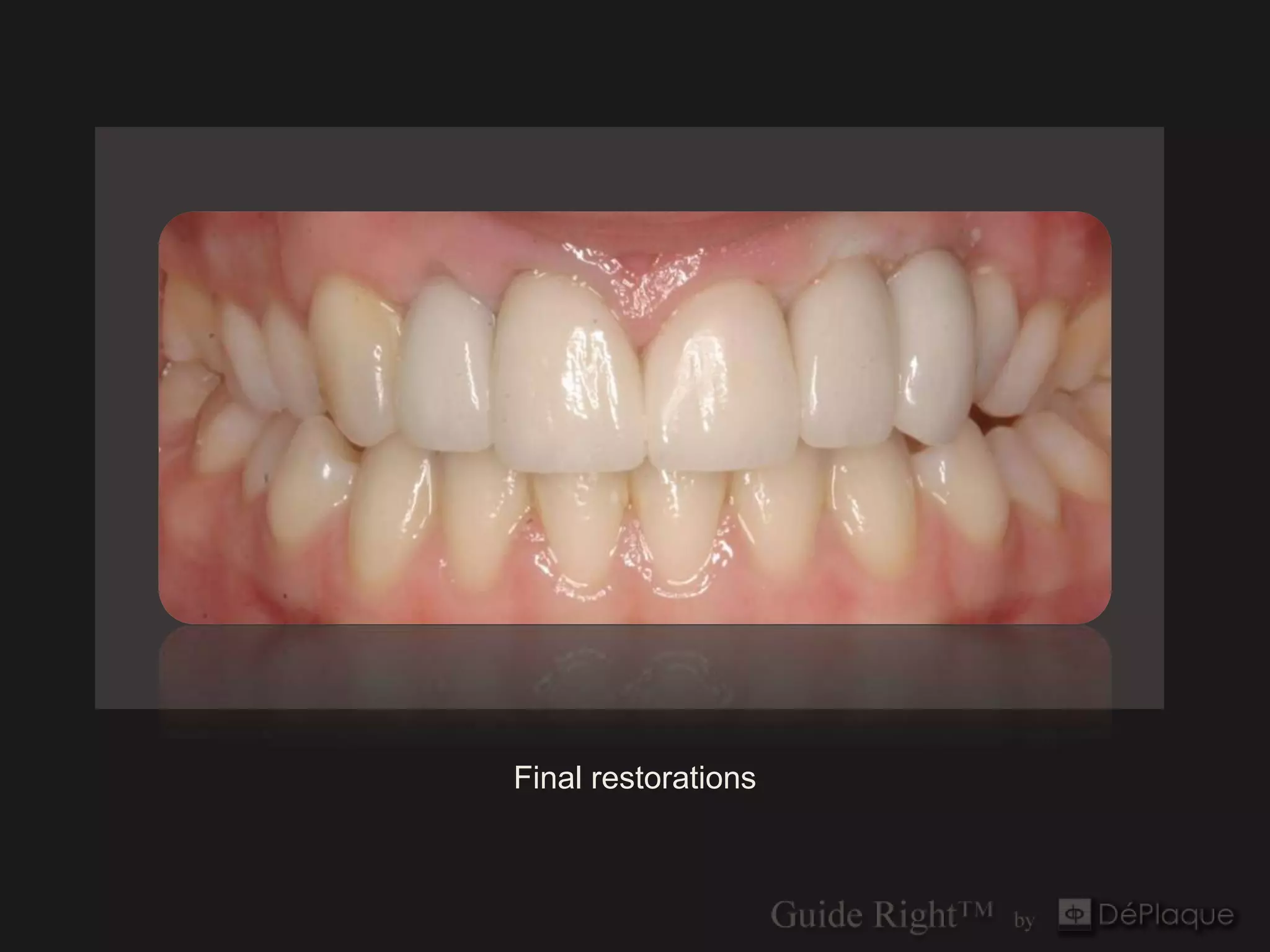
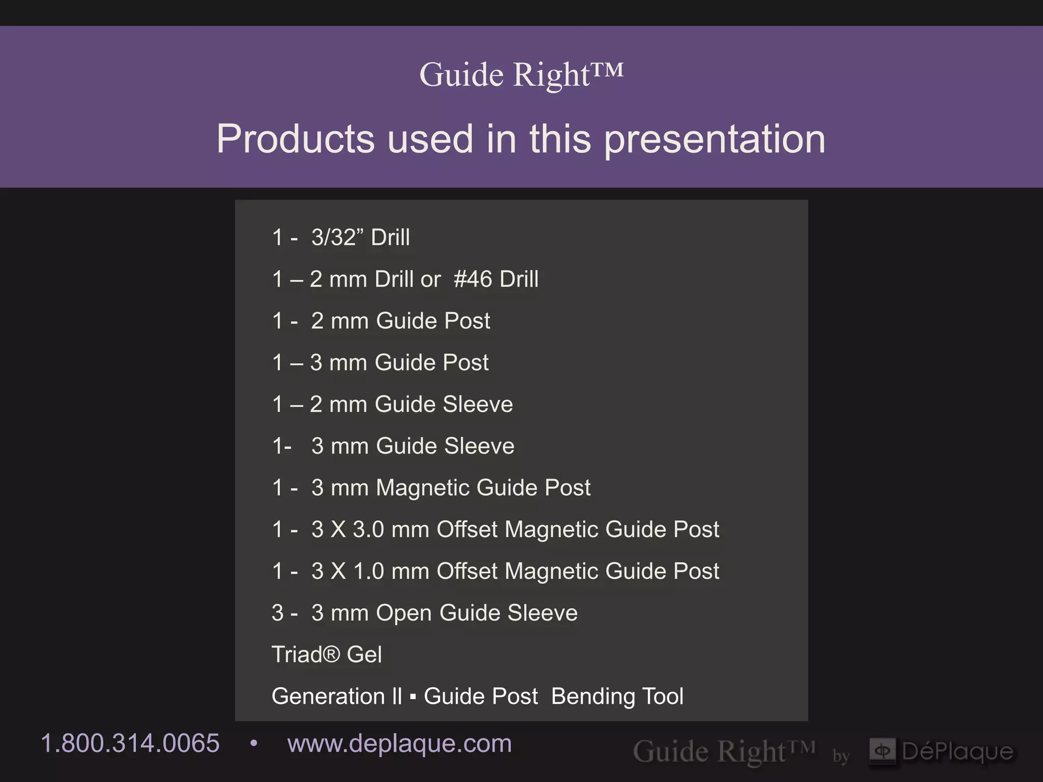
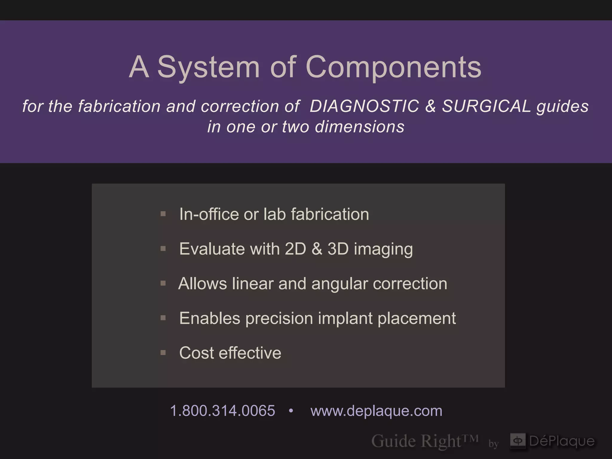

The document outlines a treatment plan using 3 mm implants for dental procedures in narrow spaces, detailing the use of guide posts and sleeves for precision placement. It elaborates on the required corrections for linear and angular adjustments at various implant sites and the fabrication of surgical guides. Additionally, it highlights the evaluation and verification processes using the invivo5 software for accurate implant positioning.


