1. FRICTION AND HEAT IN MACHINING
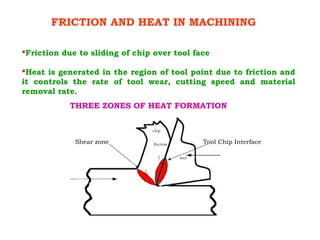
Friction due to sliding of chip over tool face
Heat is generated in the region of tool point due to friction and
it controls the rate of tool wear, cutting speed and material
removal rate.
THREE ZONES OF HEAT FORMATION
Shear zone Tool Chip Interface
2. FRICTION AND HEAT IN MACHINING
Friction due to sliding of chip over tool face
Heat is generated in the region of tool point due to friction and
it controls the rate of tool wear, cutting speed and material
removal rate.
THREE ZONES OF HEAT FORMATION
Shear zone Tool Chip Interface
Tool-work interface
11. TOOL LIFE
Tool life is defined as the effective cutting time
between resharpening.
The Taylor’s equation for tool life is
V Tn
=C
where,
V = cutting velocity in m/min.
T = tool life in minutes
n = a constant based on the tool material
C = a constant based on the tool and work
12. TOOL LIFE
Tool life is defined as the effective cutting time
between resharpening.
The Taylor’s equation for tool life is
V Tn
=C
where,
V = cutting velocity in m/min.
T = tool life in minutes
n = a constant based on the tool material
C = a constant based on the tool and work
13. PPROPERTIES OF CUTTING TOOL MATERIALS
Wear Resistance, necessary to enable the cutting tool
to retain its shape and cutting efficiency
Hot hardness, to retain the cutting ability and
hardness that may be lost due to high temperature
developed at the tool –chip interface
Toughness, to withstand the force due to cutting and
to absorb shocks and to prevent chipping of the fine
cutting edge.
14.
15.
16.
17. Grades of Tungsten Carbides (as per ISO)
ISO
APPLICATION
COLOUR
CODE
APPLICATION
P Blue
For machining long chipping
ferrous materials. – Steel
M Yellow
For machining long or short
chipping ferrous materials-
Stainless steel
K Red
For machining short chipping,
ferrous and non-ferrous
material and non-metals.- Cast
iron
18. MMATERIALS USED FOR COATING
TThe most commonly used materials for coating are
1. Titanium carbide (TiC)
2. Titanium nitride (TiN)
3. Titanium carbonitride (TiCN)
4. Aluminium oxide (Al2
O3
)
5. Aluminium oxynitride (ALON)
20. Advantages
Coating acts as a diffusion barrier
Increased hot hardness of tool
Reduced welding of chip on tool face
Low specific heat and thermal conductivity – low
interface temperature
Reduced built up edges
Reduced tendency to form comb-cracks and plastic
deformation
Wear reducing effect even when the coated layer is
interrupted
21. ISO
application
Group
Color
code
Material Process
P01 Blue Steel, Steel castings
Precision turning and boring requiring high finish and
close tolerance, high cutting speed small chip section,
no vibrations.
P10 Blue Steel, steel castings
Turning, threading and milling high cutting speed,
small or medium chip section.
P20 Blue
Steel, steel castings, malleable
cast iron forming long chips
Turning, milling, medium cutting speed and medium
chip section planning with small chip section.
P30 Blue
Steel, steel castings malleable
cast iron forming long chips
Turning, milling, planning medium or low cutting
speed, medium or large chip section under unfavorable
conditions such as changing hardness or chip section,
intermittent cut.
P40 Blue
Steel and steel casting with
sand inclusions or shrinkage
cavities
Turning, planning, shaping, low cutting speed, large
chip section under unfavorable conditions.
P50 Blue
Steel and steel castings of
medium or low tensile strength
with and large chip section
cavities
Operations requiring high toughness turning, planning,
shaping at low cutting speeds shrinkage under
unfavorable condition.
SELECTION OF CUTTING TOOLS
22. ISO
application
Group
Color
code
Material Process
M10 Yellow
Steel, steel castings, manganese
steel, grey CI., alloyed CI.
Turning, medium or high cutting speed, small or
medium chip section.
M20 Yellow
Steel, steel casting, austenitic
steal, manganese steel, Grey CI.,
spherodized CI., Malleable CI.
Turing, milling, medium cutting speed and medium
chip section.
M30 Yellow
Steel, steel casting, austenitic
steel, grey CI. spherodized C .1.
heat resisting alloys
Turning, milling, planning, medium cutting speed,
medium or large chip section.
M40 Yellow
Free cutting steel, low tensile
strength steel, brass and light
alloys
Turning, profile turning, especially in automatic
machines.
23. ISO
application
Group
Color
code
Material Process
K01 Red
Very hard grey CI. Chilled casting of
hardness up to 60 HRc. Al alloys
with high silicon, hardened steel,
abrasive plastics hard board and
ceramics
Turning, precision turning and boring, milling
scraping.
K10 Red
Grey CI. hardness> 220 HB.
Malleable CI. forming short chips,
tempered steel, Cu alloys, plastics,
glass, hard rubber, hard card board
porcelain, stone
Turning, milling, boring, reaming, broaching,
scraping.
K20 Red
Grey CI. hardness up to 220 HB. Non
ferrous metals such as Cu, Brass, AI,
abrasive laminated wood.
Turning, milling, planning, reaming, broaching,
requiring high toughness of carbide tip.
K30 Red
Soft grey C .1. Low
tensile strength steel, laminated
wood
Turning, reaming, planning, shaping under
unfavorable conditions, like changing chip
thickness, intermittent cut.
K40 Red
Soft or hard natural wood, non-
ferrous metals
Turning, milling, planning, shaping, under
unfavorable conditions like changing chip
section and intermittent cuts.
24. Cutting parameters
Material Properties Tools used Speed
m/min
Feed
mm/rev
Grey cast iron
Low strength
Hardness less than 150 BHN
and up to 300 BHN
Straight cemented carbides
Coated carbides
Ceramics
-60 to 150
-100 to 300
-350 to 700
0.1 to 1
0.1 to 1
0.1 to 0.4
White cast iron
Extremely hard up to
600 BHN
CBN or alumina based ceramics 100 to 180 0.1 to 0.4
Ductile cast iron
(SG)
Strong, tough and ductile
110 to 320 BHN
Carbides M grade
Coated carbides
50 to 120 0.1 to 1
Plain carbon steel Ductile
Cemented carbides
Coated carbides
60 to 200
90 to 400
1.2 to 0.1
0.8 to 0.1
Alloy steel
Tough, high tensile strength,
hardness, ductility and wear
resistant
Coated carbide
CBN
100 to 300 0.1 to 0.8
Tool Steel
High strength, wear resistant
and hardness impact resistant
Coated carbide
CBN
50 to 250
50 to 120
01 to 0.5
0.1 to 0.5
25. Cutting parameters
Material Properties Tools used Speed
m/min
Feed
mm/rev
Stainless steel
Austentic,
ferritic,
martensitic
High corrosion resistant,
resistant to oxidation, highly
ductile
Coated carbides
Cermets
75 to 220
80 to 180
0.8 to 0.1
0.4 to .1
Copper and its
alloys
Brass/Bronze
Ductile nd malleable Straight cemented carbides 200 to 300 0.5 to 0.1
Aluminium and
its alloys
Great strength to weight ratio Straight cemented carbides 400 to 2000 0.5 to 0.1
Nickel and its
alloys
Inconel/Hastelloy
Corrosion resistance, heat
resistance and high strength
Coated carbides
Ceramics
Cermets
CBN
20 to 100
90 to 230
30 to 150
100 to 160
0.3 to 0.1
0.3 to 0.1
0.3 to 0.1
0.2
Titanium and its
alloys
Straight tungsten carbide
K20
10 to 125 0.1 to 0.4
26. ISO CODE FOR INSERT DESIGNATION
1 2 3 4 5 6 7 8 9 10
D C M T 11 T3 O8 -26
S P K N 12 O3 ED R