Vehicle Infrastructure Integration Proof of Concept
•
2 likes•655 views

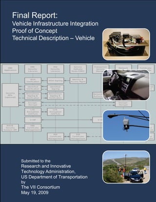
The POC system includes mobile terminals that were typically installed in vehicles. In the POC, these units are known as On-Board Equipment (OBE). OBEs exchange messages with each other for Vehicle-to-Vehicle (V2V) applications and with the stationary roadside terminals known as Road Side Equipment (RSE) for Vehicle to Infrastructure (V2I) applications. The link between OBEs and between OBEs and RSEs is the Dedicated Short Range Communications (DSRC) Radio system.

Recommended
Recommended
More Related Content
Viewers also liked
Similar to Vehicle Infrastructure Integration Proof of Concept
Similar to Vehicle Infrastructure Integration Proof of Concept (20)
Recently uploaded
Recently uploaded (20)
Vehicle Infrastructure Integration Proof of Concept
- 1. i Final Report: Vehicle Infrastructure Integration Proof of Concept Technical Description – Vehicle Submitted to the Research and Innovative Technology Administration, US Department of Transportation by The VII Consortium May 19, 2009
- 2. Notice 1 This material is based upon work supported by the United States Department of Transportation under Cooperative Agreement # DTFH61-05-H-00003. Notice 2 This report includes references to “Vehicle Infrastructure Integration” (VII). This program name was in official use at the inception of and during the execution of the work described in this report. The United States Department of Transportation has initiated a new program entitled “IntelliDriveSM ” which now encompasses all activities that were previously part of VII. Notice 3 This publication is distributed by the United States Department of Transportation in the interest of information exchange. The opinions, findings, and conclusions expressed in this publication are those of the authors and not necessarily those of the Department of Transportation. The United States Government assumes no liability for its contents or use thereof. If trade or manufacturers' names or products are mentioned, it is because they are considered essential to the object of the publication and should not be construed as an endorsement. The United States Government does not endorse products or manufacturers. Notice 4 All photos, charts, graphs, diagrams and other graphics in this document that include attribution are the property of the attributed party and are reproduced in this document with the permission of the owner. All other photos, charts, graphs, diagrams and other graphics in this document are the property of the VIIC.
- 3. Technical Report Documentation Page 1. Report No. FHWA - JPO-09-017 2. Government Accession No. 3. Recipient's Catalog No. EDL 14458 4. Title and Subtitle Final Report: Vehicle Infrastructure Integration Proof of Concept Technical Description -Vehicle 5. Report Date May 19, 2009 6. Performing Organization Code 7. Author(s) Scott Andrews, Michael Cops 8. Performing Organization Report No. 9. Performing Organization Name and Address VII Consortium, Suite 600, 39555 Orchard Hill Place, Novi, MI 48375 10. Work Unit No. (TRAIS) 11. Contract or Grant No. DTFH61-05-H-00003 12. Sponsoring Agency Name and Address U.S. Department Of Transportation Research and Innovative Technology Administration 1200 New Jersey Avenue, SE Washington, DC 20590 13. Type of Report and Period Covered Technical description of implemented VII system. Oct 2005 to Dec 2008 14. Sponsoring Agency Code 15. Supplementary Notes 16. Abstract This report provides the technical description of the VII system developed for the Cooperative Agreement VII Program between the USDOT and the VII Consortium. The basic architectural elements are summarized and detailed descriptions of the hardware and software systems are provided along with the descriptions of the applications used to assess the system performance and operation. 17. Key Words ITS Architecture, IA, Intelligent Transportation Systems, ITS, Vehicle Infrastructure Integration, VII, Architecture, Transportation, Transportation Systems, Infrastructure, Integration, IntelliDriveSM 18. Distribution Statement No restrictions. This document is available to the public. 19. Security Classif. (of this report) Unclassified 20. Security Classif. (of this page) Unclassified 21. No. of Pages 96 22. Price Form DOT F 1700.7 (8-72) Reproduction of completed page authorized
- 4. TABLE OF CONTENTS 1 ABSTRACT ......................................................................................................................................... 1 2 ORGANIZATION OF THE FINAL REPORT ................................................................................ 1 3 VII POC PROGRAM OVERVIEW .................................................................................................. 2 3.1 BACKGROUND ............................................................................................................................... 2 3.2 PROGRAM GOALS AND OBJECTIVES .............................................................................................. 2 3.3 PROJECT ROLES AND RESPONSIBILITIES ........................................................................................ 3 3.4 VII CONSORTIUM FORMATION ...................................................................................................... 3 3.5 COOPERATIVE AGREEMENT BETWEEN VIIC AND USDOT ............................................................ 4 3.6 VIIC ORGANIZATION..................................................................................................................... 5 3.7 VIIC WORK ORDER DESCRIPTION................................................................................................. 6 3.7.1 WO 1: Program Management .................................................................................................. 6 3.7.2 WO 2: Systems Engineering ..................................................................................................... 6 3.7.3 WO 3: Radio............................................................................................................................. 6 3.7.4 WO 4: Policy Support............................................................................................................... 6 3.7.5 WO 5: On Board Equipment Subsystem................................................................................... 6 3.7.6 WO 6: Application Development.............................................................................................. 7 3.7.7 WO 7: Positioning .................................................................................................................... 7 3.7.8 WO 8: Security Framework...................................................................................................... 7 3.7.9 WO 9: Testing Lab and Facilities............................................................................................. 7 3.7.10 WO 10: Field Operational Testing ........................................................................................... 7 3.7.11 WO 11: Alternative Analysis .................................................................................................... 8 3.7.12 WO 12: Private Service Enablers............................................................................................. 8 3.8 VIIC SUPPLIER SELECTION............................................................................................................ 8 3.9 COLLABORATION AGREEMENT BETWEEN VIIC AND SUPPLIERS.................................................... 9 3.10 INFRASTRUCTURE PROGRAM ......................................................................................................... 9 3.11 COMBINED PROGRAM MANAGEMENT PROCESS ............................................................................ 9 4 VII POC TECHNICAL OVERVIEW ..............................................................................................10 4.1 POC SYSTEM ARCHITECTURE DESCRIPTION ................................................................................10 4.2 CONCEPT OF OPERATIONS ............................................................................................................12 4.3 DEDICATED SHORT RANGE COMMUNICATIONS............................................................................13 4.4 SECURITY SUBSYSTEM .................................................................................................................14 4.4.1 Security Subsystem Objectives.................................................................................................15 4.4.2 Security Constraints ................................................................................................................15 4.4.3 POC Security Architecture ......................................................................................................16 4.5 ON-BOARD EQUIPMENT DESCRIPTION..........................................................................................18 4.5.1 OBE Processing Unit...............................................................................................................19 4.5.2 POC OBE Software Architecture ............................................................................................26 4.5.3 OBE Software Services............................................................................................................27 4.5.4 DSRC/GPS Antenna ................................................................................................................50 4.5.5 External Positioning Unit........................................................................................................53 4.5.6 Power Management Unit.........................................................................................................55 4.6 VIIC POC VEHICLE INTEGRATION ...............................................................................................56 4.7 POC APPLICATIONS DESCRIPTION................................................................................................59 4.7.1 POC Applications Overview....................................................................................................59 4.7.2 Tolling Payments Application..................................................................................................60 4.7.3 Parking Payment Application..................................................................................................67 4.7.4 Probe Data Collection Application .........................................................................................67 4.7.5 In-Vehicle Signage Application ...............................................................................................71 4.7.6 Trip-Path Application..............................................................................................................76 4.7.7 Off-Board Navigation Application...........................................................................................79
- 5. 4.7.8 Heartbeat Application .............................................................................................................86 4.8 NETWORK DESCRIPTION...............................................................................................................88 4.9 ROADSIDE EQUIPMENT .................................................................................................................90 4.10 SERVICE DELIVERY NODE ............................................................................................................90 4.11 CERTIFICATE AUTHORITY.............................................................................................................90 4.12 TEST TRACK .................................................................................................................................94 4.13 DEVELOPMENT TEST ENVIRONMENT............................................................................................95 TABLE OF FIGURES FIGURE 3-1 VIIC PROGRAM ORGANIZATION ............................................................................................. 5 FIGURE 4-1 OVERALL SYSTEM STRUCTURE..............................................................................................11 FIGURE 4-2 DSRC CHANNEL MANAGEMENT CONCEPT............................................................................14 FIGURE 4-3 SECURITY SUBSYSTEM TRANSACTIONS..................................................................................17 FIGURE 4-4 OBE SUBSYSTEM INTERFACE DIAGRAM................................................................................18 FIGURE 4-5 OBE SUBSYSTEM BLOCK DIAGRAM ......................................................................................19 FIGURE 4-6 DURACOR PROCESSING UNIT.................................................................................................20 FIGURE 4-7 DURACOR UNIT PHYSICAL ARCHITECTURE..........................................................................21 FIGURE 4-8 DURACOR UNIT MOTHERBOARD ..........................................................................................21 FIGURE 4-9 DSRC/WAVE RADIO POC ARCHITECTURE ..........................................................................22 FIGURE 4-10 DSRC RADIO POC ARCHITECTURE .....................................................................................23 FIGURE 4-11 DSRC RADIO MINI-PCI CARD.............................................................................................24 FIGURE 4-12 WAVE UPPER LAYER SOFTWARE POC ARCHITECTURE .....................................................25 FIGURE 4-13 HPSAM SECURITY ACCELERATOR CARD............................................................................26 FIGURE 4-14 OBE POC SOFTWARE ARCHITECTURE.................................................................................26 FIGURE 4-15 POC NETWORK SERVICES ENABLERS ARCHITECTURE ........................................................28 FIGURE 4-16 OCM....................................................................................................................................29 FIGURE 4-17 COMMUNICATIONS MANAGER SERVICE DISCOVERY SCHEME .............................................30 FIGURE 4-18 TRANSACTION SERVICES MANAGER ....................................................................................32 FIGURE 4-19 SERVICE ORCHESTRATION ...................................................................................................33 FIGURE 4-20 POC HMI MANAGER ARCHITECTURE..................................................................................34 FIGURE 4-21 HMI MANAGER EXAMPLE ...................................................................................................35 FIGURE 4-22 HMI DISPLAY PRIORITIZATION............................................................................................36 FIGURE 4-23 HMI ROAD ADVISORY TEMPLATE .......................................................................................37 FIGURE 4-24 ROAD WORK ADVISORY EXAMPLE ......................................................................................37 FIGURE 4-25 SPEED LIMIT ADVISORY EXAMPLE.......................................................................................37 FIGURE 4-26 NEXT EXIT SERVICES TEMPLATE .........................................................................................38 FIGURE 4-27 NEXT EXIT SERVICES SCREEN EXAMPLE .............................................................................39 FIGURE 4-28 GENERAL T/A TEMPLATE ....................................................................................................39 FIGURE 4-30 DRIVER ADVICE TEMPLATE .................................................................................................39 FIGURE 4-29 GENERAL T/A EXAMPLE ......................................................................................................39 FIGURE 4-31 DRIVER ADVICE EXAMPLE...................................................................................................39 FIGURE 4-32 DESTINATION SET SCREEN...................................................................................................40 FIGURE 4-33 DESTINATION SCREEN (PAGE 2)...........................................................................................40 FIGURE 4-34 OFF-BOARD NAVIGATION TURN LIST SCREEN.....................................................................40 FIGURE 4-35 ROUTE OVERVIEW SCREEN ..................................................................................................40 FIGURE 4-36 TOLL PAYMENT ON/OFF SCREEN.........................................................................................41 FIGURE 4-37 TOLL PAYMENT INFO SCREEN..............................................................................................41 FIGURE 4-38 PARKING ANNOUNCEMENT SCREEN.....................................................................................41 FIGURE 4-39 PARKING PAYMENT SCREEN ................................................................................................41 FIGURE 4-40 PARKING PAYMENT BILLING SELECTION SCREEN................................................................41 FIGURE 4-41 POC SECURITY SERVICES ARCHITECTURE...........................................................................44 FIGURE 4-42 POC POSITIONING SERVICE ARCHITECTURE........................................................................45 FIGURE 4-43 LOGICAL LAYERS OF THE VEHICLE INTERFACE....................................................................48 FIGURE 4-44 POC ARCHITECTURE OF THE LOW LEVEL CAN FRAMEWORK.............................................48 FIGURE 4-45 VAPI ARCHITECTURE ..........................................................................................................49
- 6. FIGURE 4-46 PLANAR DUAL GPS/DSRC ANTENNA ELEMENT .................................................................51 FIGURE 4-47 GPS ANTENNA GAIN............................................................................................................52 FIGURE 4-48 DSRC ANTENNA GAIN.........................................................................................................52 FIGURE 4-49 DUAL DSRC/GPS PLANAR ANTENNA PACKAGE AND CABLING..........................................53 FIGURE 4-50 ANTENNA MOUNTED ON POC VEHICLE...............................................................................53 FIGURE 4-51 OBE POSITIONING SUBSYSTEM............................................................................................54 FIGURE 4-52 SIRFSTAR POSITIONING UNIT..............................................................................................55 FIGURE 4-53 SIRFSTAR II AND U-BLOX POSITIONING UNITS...................................................................55 FIGURE 4-54 CARNETIX POWER MANAGEMENT UNIT ..............................................................................55 FIGURE 4-55 CARNETIX POWER MANAGEMENT CONTROLS.....................................................................56 FIGURE 4-56 OBE SUBSYSTEM ASSEMBLY...............................................................................................57 FIGURE 4-57 OBE CABLING ASSEMBLY ...................................................................................................57 FIGURE 4-58 OBE TRUNK MOUNTING......................................................................................................58 FIGURE 4-59 HMI EXTERNAL DASH MOUNT............................................................................................58 FIGURE 4-60 HMI IN-DASH MOUNT .........................................................................................................59 FIGURE 4-61 OBE ROOF MOUNT DSRC/GPS ANTENNA..........................................................................59 FIGURE 4-62 PAYMENT FOR TOLL APPLICATION SYSTEM OVERLAY DIAGRAM........................................62 FIGURE 4-63 PAYMENT FOR TOLL COMPONENT DIAGRAM .......................................................................63 FIGURE 4-64 IN-VEHICLE COMPONENT OVERVIEW ..................................................................................63 FIGURE 4-65 TOLL PAYMENT SCREEN ......................................................................................................64 FIGURE 4-66 LTP COMPONENT OVERVIEW ..............................................................................................65 FIGURE 4-67 NUC OVERVIEW ..................................................................................................................65 FIGURE 4-68 VEHICLE PROBE DATA GENERATION APPLICATION SYSTEM OVERLAY DIAGRAM ..............68 FIGURE 4-69 PDVC FUNCTIONAL ELEMENTS OVERVIEW.........................................................................69 FIGURE 4-70 IN-VEHICLE SIGNAGE APPLICATION SYSTEM OVERLAY DIAGRAM......................................72 FIGURE 4-71 POC SIGNAGE APPLICATION ARCHITECTURE ......................................................................73 FIGURE 4-72 NETWORK SIGNAGE COMPONENT FUNCTIONAL ELEMENTS OVERVIEW ..............................73 FIGURE 4-73 VEHICLE SIGNAGE COMPONENT FUNCTIONAL ELEMENTS OVERVIEW.................................74 FIGURE 4-74 EXAMPLE ROAD ADVISORY .................................................................................................75 FIGURE 4-75 EXAMPLE NEXT EXIT SERVICES DISPLAY ............................................................................75 FIGURE 4-76 TRIP-PATH APPLICATION SYSTEM OVERLAY DIAGRAM ......................................................77 FIGURE 4-77 VEHICLE TRIP-PATH GENERATION FUNCTIONAL ELEMENTS OVERVIEW .............................77 FIGURE 4-78 OBNA SYSTEM OVERLAY DIAGRAM...................................................................................80 FIGURE 4-79 OBNA FUNCTIONAL COMPONENT DIAGRAM ......................................................................80 FIGURE 4-80 VEHICLE COMPONENT FUNCTIONAL ELEMENTS ..................................................................81 FIGURE 4-81 EXAMPLE DESTINATION LIST...............................................................................................82 FIGURE 4-82 ROUTE OVERVIEW SCREEN ..................................................................................................82 FIGURE 4-83 MANEUVER DIAGRAM DISPLAY...........................................................................................83 FIGURE 4-84 OFF-BOARD NAVIGATION NETWORK COMPONENT FUNCTIONAL ELEMENTS ......................83 FIGURE 4-85 OBNA OVERVIEW MAP.......................................................................................................84 FIGURE 4-86 OBNA MANEUVER MAP......................................................................................................85 FIGURE 4-87 VEHICLE HEARTBEAT GENERATION APPLICATION SYSTEM OVERLAY DIAGRAM................86 FIGURE 4-88 HEARTBEAT VEHICLE COMPONENT FUNCTIONAL ELEMENTS OVERVIEW............................87 FIGURE 4-89 INFRASTRUCTURE SIDE SYSTEM ..........................................................................................88 FIGURE 4-90 CA STRUCTURE....................................................................................................................91 FIGURE 4-91 ANONYMOUS CERTIFICATE MANAGEMENT..........................................................................93 FIGURE 4-92 TEST TRACK FACILITY .........................................................................................................95 FIGURE 4-93 OVERALL VII NETWORK SYSTEM ........................................................................................95 FIGURE 4-94 DEMONSTRATION TEST ENVIRONMENT MAP .......................................................................96 FIGURE 4-95 TYPICAL RSE INSTALLATION...............................................................................................96 TABLE OF TABLES TABLE 1 COOPERATIVE AGREEMENT WORK ORDERS................................................................................ 5 TABLE 2 VIIC SUPPLIER INVOLVEMENTS IN WORK ORDERS ..................................................................... 9 TABLE 3 ROLES AND RESPONSIBILITIES OF BAH TEAM............................................................................. 9
- 7. GLOSSARY OF TERMS AND ACRONYMS 3G Third Generation Cellular (Wireless Data System) AASHTO American Association of State Highway and Transportation Officials AOCA Anonymous OBE Certifying Authority AMDS Advisory Message Delivery Service API Application Programming Interface BAH Booz Allen Hamilton BER Burst Error Rate BMW BMW of North America, LLC BSP Board Support Package CA Certificate Authority CAN Controller Area Network CCL Channel Coordination Layer CCH Control Channel CEP Circular Error Probable CM Certificate Manager COTS Commercial Off-the-Shelf CPU Central Processing Unit CRL Certificate Revocation List DGPS Differential Global Positioning System DSRC Dedicated Short Range Communications DTE Development Test Environment ECC Elliptic Curve Cryptography ENOC Enterprise Network Operations Center ESB Enterprise Service Bus XML Extensible Markup Language FCC Federal Communications Commission FHWA Federal Highway Administration FPGA Field Programmable Gate Array Gbps Gigabit Per Second GHz Giga-Hertz GID Geographic Intersection Description GM General Motors Corporation GPS Global Positioning System HANDGPS High Accuracy National Differential GPS HB Heartbeat HIP Host Identity Protocol HMI Human Machine Interface HPSAM High Performance Security Accelerating Module HTTP Hypertext Transfer Protocol ILS Information Lookup Service IP Internet Protocol IPv4 Internet Protocol Version 4 IPv6 Internet Protocol Version 6 ISO International Standards Organization IVI Intelligent Vehicle Initiative
- 8. I2V Infrastructure to Vehicle IVPS In-Vehicle Payment Service IVTP In-Vehicle Toll Processing ITS Intelligent Transportation Systems JMS Java Message Service JVM Java Virtual Machine LIN Local Interconnect Network LLCF Low Level CAN Framework LTP Local Transaction Processor LTTP LTP Toll Processing MAC Medium Access Control MDOT Michigan Department of Transportation MEDS Map Element Distribution System MEG Map Element Generator MHz Mega-Hertz MINAP Michigan Network Access Point MTU Maximum Transmission Unit NTPDA Network Trip Path Data Accumulator NUC Network User Component NUG Network User Gateway NUPS Network Users Payment Service OAA OBE Authorizing Authority OBE On-Board Equipment OCM OBE Communications Manager OEM Original Equipment Manufacturer OBNA Off-Board Navigation Application OS Operating System OSGi Open Services Gateway Initiative PC Personal Computer PCI Peripheral Component Interconnect PDC Probe Data Collection PDCS Probe Data Collection Service PDDS Probe Data Distribution Service PDSS Probe Data Subscription Service PDM Probe Data Management PDU Protocol Data Units PDS Probe Data Service PDVC Probe Data Vehicle Component PER Packer Error Rate PKI Public Key Infrastructure POC Proof of Concept PSC Provider Service Context PSID Provider Service Identifier PSN Probe Sequence Number RCOC Road Commission for Oakland County RF Radio Frequency RITA Research and Innovative Technology Administration RSE Roadside Equipment SAE Society of Automotive Engineers
- 9. SCH Service Channel SDN Service Delivery Node SDRAM Synchronous Dynamic Random Access Memory SIT (Tunnel) Simple Internet Transition (Tunnel) SOA Service Oriented Architecture SOAP Simple Object Access Protocol SPAT Signal Phase and Timing SRS Software Requirement Specification TCP/IP Transmission Control Protocol/ Internet Protocol TMT Technical Management Team TPGA Trip-Path General Application TPT Trip-Path Transmission TSM Transaction Service Manager UDP Universal Datagram Protocol URL Uniform Resource Locator USDOT United States Department of Transportation V2I Vehicle to Infrastructure V2V Vehicle to Vehicle VAPI Vehicle Application Programming Interface V-DTLS VII-Datagram Transport Layer Security VEG Vehicle Expert Group V-HIP VII-Host Identity Protocol VGA Video Graphics Array VIDMT Vehicle Interface Device Management Tree VII Vehicle Infrastructure Integration VIIC Vehicle Infrastructure Integration Consortium VIN Vehicle Identification Number VIS Vehicle Interface Service VPN Virtual Private Network VSC Vehicle Signage Component VW Volkswagen of America WAAS Wide Area Augmentation System WAVE Wireless Access in Vehicular Environments WME Wave Management Entity WO Work Order WSA WAVE Service Advertisement WSC WAVE Security Context WSMP WAVE Short Message Protocol
- 10. 1 1 Abstract This report provides the technical description of the Vehicle Infrastructure Integration (VII) system developed for the Cooperative Agreement Program between the United States Department of Transportation (USDOT) and Vehicle Infrastructure Integration Consortium (VIIC). The basic architectural elements are summarized and detailed descriptions of the hardware and software systems are provided along with the descriptions of the applications used to assess the system. 2 Organization of the Final Report The VII Cooperative Agreement Program final report is organized into five volumes: Volume 1a -- Final Report: VII Proof of Concept Executive Summary – Vehicle This volume provides an overview of the program goals and objectives, program organization, program technical direction and the key findings and recommendations. The report does not detail test results. This report is recommended for executives and managers of VII communities concerned with the deployment of VII systems. Volume 2a -- Final Report: VII Proof of Concept Technical Description – Vehicle This volume describes the technical approach of the program and specifically describes the VII POC system architecture, the system component design and the sample applications designed to enable some of the system testing. In addition the deployment of the system to the test track and Development Test Environment (DTE) is described. This report is recommended for engineering managers and practicing engineers concerned with the deployment of VII systems. Volume 3a -- Final Report: VII Proof of Concept Results and Findings Summary – Vehicle This volume describes the test objectives and approach and presents a summary of results and findings for both the system testing and the application testing. Detailed results are not presented. This report is recommended for engineering managers and engineers concerned with the deployment of VII systems. It assumes the reader has knowledge of the VII POC system architecture as described in Volume 2a. Volume 4a -- Final Report: VII Proof of Concept System Detailed Test Results – Vehicle This volume describes the system test objectives, the system test approach and details the results of the individual components and the end-to-end system tests. This report is recommended for engineers concerned with the deployment of VII systems. It assumes the reader has knowledge of the VII POC system architecture and components as described in Volume 2a. Volume 5a -- Final Report: VII Proof of Concept Application Detailed Test Results – Vehicle This volume describes application test objectives, the application test approach and details the results of the individual application tests. This report is recommended for engineers concerned with the deployment of VII systems and the design of VII applications. It assumes the reader has knowledge of the VII POC system architecture and applications as described in Volume 2a. Volumes 1a, 2a and 3a have complimentary reports: Volumes 1b, 2b and 3b, which describe the development and testing of the POC Infrastructure written by Booz Allen Hamilton (BAH).
- 11. 2 3 VII POC Program Overview 3.1 Background During the 10th World Congress held in Madrid, Spain (November 2003), the USDOT announced a new initiative, namely, VII. This initiative represents the confluence of three areas of high interest to transportation policy managers: the Intelligent Vehicle Initiative (IVI), an emphasis on improved traffic operations, and the continuing evolution in telecommunication technology. Regarding the latter item, the Federal Communications Commission (FCC) has allocated 75 MHz at 5.9 GHz for the primary purpose of improving transportation safety. In addition to safety of life and public safety applications, the FCC’s Final Report and Order also allows private and non- safety applications to make use of the spectrum on a lower priority basis. Dedicated Short Range Communications (DSRC), the wireless medium, will allow vehicles to communicate with a low- cost roadside infrastructure, as well as with each other, in real time. This communications capability, in combination with a nationwide data collection and processing network, will facilitate improvements to safety, mobility and productivity/convenience. Reducing the number and severity of roadway transportation incidents is a top priority of the USDOT. Development of a system supporting communication between vehicles and between vehicles and a roadway infrastructure has the potential for positively contributing to the government’s goal of improving transportation safety. Such real-time communications would enable a range of crash avoidance and crash mitigation applications with the potential to reduce traffic deaths and injuries, while simultaneously enabling a host of additional applications with secondary benefits, such as optimized traffic and incident management systems. To enable this vision, it was proposed to undertake a project to specify, design, build and test a small-scale instantiation of the envisioned national system to determine if the concept was sound and could support the intended use. Pending the anticipated results of the system’s testing, a nationwide system would be deployed. It was understood that the success of the project required close collaboration between the USDOT, the State Departments of Transportation through the American Association of State Highway and Transportation Officials (AASHTO), and light-duty vehicle manufacturers. These primary stakeholders were brought together by the USDOT in the National Vehicle Infrastructure Integration Coalition. 3.2 Program Goals and Objectives The original program goals included development and testing of a concept system that could be nationally deployed beginning some time around 2010, to provide a mechanism for wirelessly sending and receiving roadway information to and from vehicles, and between vehicles to satisfy the following viability criteria*: Safety − Provides for infrastructure initiated safety applications. − Supports vehicle initiated safety applications. Mobility − Provides for collection of various mobility data from vehicles. − Provides for use of collected mobility data by state and local authorities. − Exhibits sufficient benefit in terms of road and traffic management and transportation efficiency.
- 12. 3 Private Services − Vehicles can access private services through the system. − Private services can access vehicles through the system. − Co-existence of private services with safety and mobility services is economically viable. − Private services can be implemented in a manner that does not interfere with safety and mobility applications. Security − System is resistant to denial of service, replay and intrusion attacks. − Security compromises can be identified and mitigated. − Security credentials can be properly distributed and managed at all levels of deployment. Maintainability − Roadside Equipment (RSE) software can be remotely managed through the network. − VII-related vehicle software can be securely maintained over the vehicle life cycle. Privacy − Cannot track an individual vehicle over any road segment longer than 2 km. − Cannot identify any individual vehicle as violating a traffic law through publicly collected data. − Cannot identify a vehicle or a vehicle occupant or owner from messages sent to, or through, the infrastructure. * Note: These criteria were developed by the VIIC at the start of the program. They were agreed upon between the VIIC members and the USDOT. Other criteria have been proposed, but as of this date, none have been fully agreed upon by all of the VII stakeholders. The other criteria are generally a simplified and less comprehensive set, relative to the criteria presented here. These criteria are used for completeness, and in general, any differences between this set and the others discussed are minor. 3.3 Project Roles and Responsibilities The system concept was understood to consist of a roadside network component and an on-board vehicle equipment component. The responsibility for the network and roadside equipment was assigned to BAH, a USDOT contractor, and the On-Board Equipment (OBE) to light-duty vehicle manufacturers, represented by the VIIC. Additionally, it was anticipated that typical applications would be designed and tested as a part of the project. The responsibility for public applications, i.e. those to be used by the Federal and state governments, was assigned to BAH and those likely to be used by the vehicle manufacturers and providers of the commercial services were assigned to the VIIC and their suppliers for development. The USDOT’s Intelligent Transportation Systems (ITS) Joint Program Office provided oversight and program management. Funding for the program was shared between USDOT and the VIIC, with the USDOT providing the majority share. 3.4 VII Consortium Formation The VIIC was formed in February 2005 by three manufacturers of light-duty vehicles for the specific purpose of actively engaging in the design, testing and evaluation of a deployable VII system for the United States. The Consortium was also formed to provide a contracting
- 13. 4 mechanism for the Cooperative Agreement that was later established with the USDOT Federal Highway Administration (FHWA). Initial membership included Daimler-Chrysler, Ford Motor Company and Nissan Technical Center North America, Inc. Subsequently, the membership increased to include BMW of North America, LLC, General Motors Corporation, Honda R&D Americas, Inc, Toyota Motor Engineering and Manufacturing North America, Inc. and Volkswagen of America, Inc.(VW). Since the split of the Daimler-Chrysler organization, both Mercedes-Benz Research and Development North America, Inc. and Chrysler LLC have retained memberships resulting in the VIIC membership totaling nine light-duty vehicle manufacturers at the time of this report publication. The Consortium is a Michigan 501(c)(6) non-profit organization. 3.5 Cooperative Agreement between VIIC and USDOT A Cooperative Agreement between the USDOT FHWA and the VIIC was executed on December 7, 2005. The objectives of this agreement are: − Analysis of the requirements to permit the auto industry to provide a coordinated input to the Vehicle Infrastructure Integration Coalition − Analysis of the requirements and definition of specific design elements of the VII architecture − Design of specific hardware to facilitate the implementation of the VII system − Develop software that could be employed either on the vehicle or in the infrastructure − Fabrication or procurement of equipment to be used in the test and evaluation of the VII program − Testing of specific elements and /or combinations of elements of the VII architecture − Integration of elements of the VII architecture to permit evaluation of the design − Evaluation of the effectiveness of specific designs with respect to the stated objectives of VII − Analysis of data and results of the VII program. The period of performance of the Cooperative Agreement is 60 months.
- 14. 5 3.6 VIIC Organization The VIIC organization is detailed in Figure 3-1. Figure 3-1 VIIC Program Organization The VIIC Management Committee consisting of members from each of the VIIC participating vehicle manufacturers report to the VIIC Board of Directors, which is responsible for carrying out the charter outlined in the Articles of Incorporation. The Management Committee manages the daily operations of the VIIC through three committees: the Technical Oversight Committee, the Policy Committee and the Outreach Committee. The program is subdivided into a series of twelve (12) Work Orders detailed in Table 1 for executing the technical work policy and outreach programs. The Policy and Outreach Committees have jurisdiction over the Policy Work Order (WO) and the Technical Oversight Committee has jurisdiction over the remaining WOs dealing with technical content of the program through the office of the Program Manager. Each WO is managed by a Technical Management Team (TMT) leader who is responsible for the technical direction, delivering the work products and maintaining the schedule for the deliverables. Work Order # Work Order Title Work Order # Work Order Title 1 Program Management 7 Positioning 2 Systems Engineering 8 Security Framework 3 Radio 9 Testing Lab and Facilities 4 Policy Support 10 Field Operational Test* 5 OBE Subsystem 11 Alternative Analyses* 6 Application Development 12 Private Service Enablers * Not initiated Table 1 Cooperative Agreement Work Orders
- 15. 6 3.7 VIIC Work Order Description As mentioned previously, the POC program portion of the Cooperative Agreement work was broken down into twelve (12) WOs. The following is a description of each WO as they pertain to the POC. The suppliers in each WO are shown in Table 2. 3.7.1 WO 1: Program Management Tasks included program management of the overall project including the delivery of all work products on time and within budget. Tasks also included the oversight of the Technical, Policy and Outreach Committees by the Management Committee. Other tasks not included in other WOs were included in this WO. Deliverables included weekly and quarterly reports detailing progress and expenditure, and quarterly Program Management Reviews. 3.7.2 WO 2: Systems Engineering Tasks included development of system requirements, allocation of requirements to system components and interface specifications, oversight of interface documentation between WO initiatives, development of test plans and procedures, system and application testing, reports analysis and reporting. Deliverables included systems engineering and test master plans, VII POC architecture documentation, requirement specifications, requirements allocation documentation, test plans and procedures, test results and final test reports. 3.7.3 WO 3: Radio Tasks included designing a compatible radio, based on the IEEE 802.11(p) and IEEE P1609.2, P1609.3 and P1609.4 specifications. Also included are the development of specifications and development of all software and testing of the completed work product. The tasks also included feedback to the standards committees and conducting a scalability study. Deliverables included radio design specifications, source code for all layers, physical delivery of dual antennas, test plans and results and feedback to the standards committees. 3.7.4 WO 4: Policy Support POC tasks included guidance on Human Machine Interface (HMI) implementation and analysis of testing implications, antitrust issues, patent analysis and patent guidance. Deliverables included HMI guidelines, guidance to WO teams concerning federal, state and local law compliance, antitrust guidelines, patent infringement and patent defense analysis, deployment plan and business case recommendations and legal obligations. 3.7.5 WO 5: On-Board Equipment Subsystem Tasks included the development of various design specifications, selection and procurement of a hardware platform, selection of various operating systems and the development of some of the base services including the HMI, power management and vehicle interface. Also included was the
- 16. 7 responsibility for integration of all service components resident on the platform, but designed in other work orders. Deliverables included OBE hardware and HMI specifications, production of a number of dual- purpose antennas, vehicle interface specifications, protocol documentations, interface and final test procedures. 3.7.6 WO 6: Application Development Tasks included the development of requirements, design specification and the development and testing of on-board and off-board network components for various applications. The applications developed were In-Vehicle Signage, Probe Data Collection (PDC), Off-Board Navigation, Tolling and Parking Payments and Trip-Path Data Collection. Deliverables included updated use cases, Software Requirements Specifications (SRS), executable code, unit level and integration test reports. 3.7.7 WO 7: Positioning Tasks included the development of requirements for a Commercial Off-the-Shelf (COTS) positioning system, procurement and testing of same, and the development of a Positioning service and system clock for integration into the OBE. Deliverables included positioning requirements, Application Programming Interfaces (APIs), executable software, physical hardware, High Accuracy National Differential GPS (HANDGPS) reference station and final test and qualifications plans and reports. 3.7.8 WO 8: Security Framework Tasks included the development of a security system in accordance with IEEE P1609.2. This included the development of requirements and design specifications for the framework and the development and integration testing of the system components for both the OBE and RSE. The system components included the Certificate Authority (CA), Certificate Manager (CM), Security Cryptographic libraries and a hardware accelerator to support the libraries. Also included was a study of security system vulnerability. Deliverables included security concept of operations, scalability and threat analysis white papers, CM process specification, POC software architecture and SRS, executable code, software libraries, hardware accelerator boards and probe data encoder. 3.7.9 WO 9: Testing Lab and Facilities Tasks included the completion of all test plans and procedures, the testing of Communication, Positioning, Vehicle Interface and Security services, integration testing and final testing of applications as part of system end-to-end testing. Also included in the WO were tasks to analyze all results and develop associated reports. Deliverables included critique of all test plans prepared by others, subsystem component and test equipment supply, test plans and procedures for all services and applications integration test plans, test results for all services testing and final test reports. 3.7.10 WO 10: Field Operational Testing This WO has not been developed or funded.
- 17. 8 3.7.11 WO 11: Alternative Analysis This WO has not been developed or funded. 3.7.12 WO 12: Private Service Enablers Tasks included the development of requirements for methods to connect private services to the network in order to conduct point-to-point transactions across multiple RSEs. Included in the work order were the development of OBE and network components and associated protocols to facilitate point-to-point transactions. Deliverables included requirements specifications, VII POC architecture design, component analysis and selection, software specifications, executable code and acceptance test plans and results. 3.8 VIIC Supplier Selection The design of a complex system required the expertise of companies with a wide range of diverse skills ranging from automotive electronics to networking systems. It was also recognized that the inclusion of a significant number of suppliers in the program would involve related industries and help to accelerate industry involvement. Invitations to submit proposals were sent to approximately 100 suppliers known to have an interest and the capabilities to develop the VII system. Proposals were reviewed and selections of the final supplier candidates were made by the program team including the VIIC membership. Table 2 details the supplier involvement for each WO. Supplier WO Number* 1 2 3 4 5 6 7 8 9 12 ABSS Inc. X ARINC Inc. X Battelle Institute X X BMW X X X X Chrysler LLC. X X X X X X Cogenia Partners LLC. X X X X Delphi Automotive Systems Inc X X Denso International America, X X Dykema Gossett X Ford Motor Company X X X X Honda R&D Americas Inc. X X X Intel Americas Inc. X Mark IV IVHS Inc. X Mercedes-Benz X X X X Moser Racing LLC. X MTS LLC. X Navteq North America LLC. X Nissan Technical Center NA X X X Ntru Cryptosystems Inc. X Parvus Corporation X Prosyst Software Gmbh. X Raytheon Company X X Roush Industries X Sirit Technology Inc. X Technocom (now Kapsch TrafficCom) X X X Telcordia Technologies X X Toyota Motor Engineering and X X X
- 18. 9 Manufacturing NA Inc. Transcore LP. X Volkswagen X X X WFET Group X X Wind River Systems Inc. X *WOs 10 and 11 not initiated Table 2 VIIC Supplier Involvement in Work Orders 3.9 Collaboration Agreement between VIIC and Suppliers The Collaboration Agreement was developed to protect the intellectual property right of the WO Participants. The Collaboration Agreement was used in WOs where intellectual property was likely to be used or developed. Each WO was supported by a number of suppliers as detailed in Table 2. As a result of the Collaboration Agreement, these teams of suppliers were able to work collaboratively in a pre-competitive environment. 3.10 Infrastructure Program BAH acted as the system integrator for the infrastructure and public applications, while the VIIC led the development and testing of the OBE and private applications including test applications to determine the systems capability to support safety applications. The BAH team consisted of Iteris, Raytheon, Sirit, Technocom and Telcordia. Local support in Michigan was provided by the Michigan Department of Transportation (MDOT) and Road Commission for Oakland County (RCOC). Prgram Mgmt System Eng SDN ENOC &CA RSE DTE SIT Public Apps POC Testing O&M Stds Booz Allen Hamilton X X X X X X X X X X X Iteris X X X MDOT/RCOC X X X Raytheon X X X X X Sirit X X Technocom/Kapsch X X Telcordia X X X X Table 3 Roles and Responsibilities of BAH Team 3.11 Combined Program Management Process Formal program management processes were applied as appropriate for the size and complexity of the program. The need for this was accentuated by the number of WOs, (the relatively large number of suppliers spread across two continents) and the assignment of responsibilities between VIIC and BAH as described in Section 3.3. To achieve this goal, the program was broken down into the following tasks: 1. Collect stakeholder requirements. 2. Develop a concept of operations for the system, based on stakeholder requirements. 3. Develop requirements for the system concept and its components. 4. Develop or procure the components according to the requirements. 5. Assemble and deploy a small scale version of the system. 6. Perform integration testing. 7. Perform system testing against performance specifications.
- 19. 10 8. Analyze results and determine if the viability criteria for the system had been met. 9. Report on the findings of the program. The formal processes employed to manage the program included: − Weekly WO program progress meetings with the TMT leaders chaired by the Program Manager. − Weekly WO supplier progress and technical meetings chaired by TMT leaders. − Weekly coordination meetings between VIIC and BAH. − Weekly reporting to the USDOT. − Quarterly Program Management Reviews with the USDOT and supply community. − Engineering Review Board Meetings (VIIC only). − Configuration Control Board Meetings. − System Integration Team meetings to review and discuss component interfaces and operation. These meetings were, on occasion, held on a daily basis to resolve difficult and urgent technical issues. Tools used for program management included Microsoft Project for project scheduling and task completion assessment and QuickBooks for project accounting. 4 VII POC Technical Overview 4.1 POC System Architecture Description The POC system includes mobile terminals that were typically installed in vehicles. In the POC, these units are known as On-Board Equipment (OBE). OBEs exchange messages with each other for Vehicle-to-Vehicle (V2V) applications and with the stationary roadside terminals known as Road Side Equipment (RSE) for Vehicle to Infrastructure (V2I) applications. The link between OBEs and between OBEs and RSEs is the Dedicated Short Range Communications (DSRC) Radio system. The RSEs are connected to, and are remotely managed from a Service Delivery Node (SDN) and an Enterprise Network Operations Center (ENOC). The SDN provides a variety of services that are described in more detail in subsequent sections. A critical aspect of the VII architecture is the management of scale. The system needs to be designed to support 100% vehicle deployment, which translates to just over 200 million vehicles. In operation, this means that applications such as PDC may be handling tens of millions of messages per second, across the entire network. The system must allow a single user to post, for example, a warning sign in the vicinity of a particular hazard. To manage these large-scale extremes, the system uses a tiered tree-like architecture (See Figure 4-1). As can be seen in the figure, any given RSE needs to be capable of interacting with up to 250 vehicles at any given time. This is determined primarily by the number of vehicles that can fit inside a typical Radio Frequency (RF) footprint, which provides a range of approximately 250 m.
- 20. 11 Figure 4-1 Overall System Structure Each RSE is connected to a regional SDN via a backhaul link, and each SDN is connected to all other SDNs via a wide band backbone network. Using this architecture, any RSE is accessible from any SDN, and this is a key feature of the scalability of the system, since any user connecting to the local SDN can interact with any RSE. A typical SDN is expected to support between 1000 to 2000 RSEs, so, for a nationwide deployment there might be between 100 and 200 SDNs. The SDN provides a variety of services, but key to the discussion of scaling are the Advisory Message Delivery Service (AMDS), the Probe Data Collection Service (PDCS) and the Network User Gateway (NUG). The AMDS serves as a link between network users who have advisory messages to distribute and the entire installed base of RSEs (and therefore the entire OBE population). In one possible deployment scenario, it is expected that the number of signage providers will be less than about 10,000, so for signage, the system allows 10,000 providers to efficiently interact with 200,000 RSEs and deliver signage messages to 200 million OBEs. In the reverse direction, the PDC collects probe data from all of the RSEs attached to the SDN. This data is parsed into data “topics,” and then data for any given topic is distributed to network users who have subscribed to that particular topic. A typical topic might be instantaneous road speed at a particular location on a particular road. This scheme allows the system to collect vast amounts of data from vehicles on the road, and sub-divide the data passing only those parts of interest to any given subscriber. It is expected that there may be about 10,000 to 100,000 probe data subscribers, and as with AMDS, the system effectively scales from over 200 million vehicles (generating roughly 50 Gbps) to about 50,000 users of this data. The SDN also provides a simple routing system that links vehicle users with private service providers in either one-to-one or one-to-many relationships. In this role,
- 21. 12 the SDN is effectively like a mobile Internet system linking users to web service centers such as navigation providers. The POC implementation of the system includes 55 RSEs placed at various locations in the northwestern Detroit suburbs. These RSEs are linked to two different SDNs using a variety of different backhaul technologies. One SDN is located in Novi, Michigan, and the other is located in Herndon, Virginia. The Herndon facility also includes an ENOC and the CA required to support security functions. The POC implementation is thus a minimalist version of the national system architecture allowing the program to assess the operational behavior of the system as if it were a full-scaled deployment. 4.2 Concept of Operations Conceptually, the system provides several core functions from which a suite of applications may be created. The POC system: − Delivers broadcast messages from network providers to OBEs at specified geographic locations − Delivers broadcast messages from local systems such as traffic signals or toll stations to OBEs at specified geographic locations − Delivers broadcast messages between OBEs − Collects data from OBEs and distributes topical information extracted from the data to network subscribers − Provides OBEs access to remote private service providers, and this access can be carried over from one RSE to the next without disrupting the service − Provides security functions to protect against attacks and to protect the privacy of the individual users. As part of the overall VII program, a set of approximately 100 use cases or applications were developed by various stakeholder groups. In general, these descriptions did not fully articulate the use cases in the context of the system, but they did provide insight into the needs and priorities of the various stakeholders. From this initial set, 20 use cases were expected to be available at the system’s initial deployment and were identified and articulated in more detail. This group is known as the “Day-1 Use Cases.” Because developing and testing all 20 Day-1 Use Cases would have been impracticable, the POC program identified a subset of use cases that exercised the core functions described above. These were then implemented and tested in ways to assess both the functionality of the system and the baseline performance, under the assumption that the system would provide these core functions in the same way regardless of the specific details of the application. In several of the safety applications, the use cases were scaled back to allow the assessment of key architectural and system aspects without requiring development of a full-blown application. This report focuses on the VIIC’s developed and tested POC applications described in the following sections.
- 22. 13 4.3 Dedicated Short Range Communications The 75 MHz band in the 5.9 GHz frequency range allocated by the FCC offers significant data transfer capacity. However, to make use of this spectrum in a mobile environment required development of new communications protocols. The core radio protocol used is based on the well-known IEEE 802.11a/b/g wireless Ethernet standard, often referred to as WiFi. Because of the unique mobile environment, the IEEE 802.11a standard was modified to allow what is known as an “association-less” protocol, identified as IEEE 802.11p. This means that the system does not establish a conventional network with all of the mobile terminals as nodes, all of which know about each other. The reason this is not done is that the mobile terminals (OBEs in the POC) are entering and leaving the hot spot rapidly, and there is insufficient time available to set up a new network identity for each new arrival, and inform all other nodes in the network before the network changes again because a terminal has left the footprint of the RSE, or a new one has arrived. On the surface, this approach may seem to limit the functionality of the system since it means that any given mobile terminal cannot interact uniquely with another terminal (the way computers on an office network might), but this is not the case. Because the system is radio based, all terminals can hear all messages sent. Since, under most circumstances one can simply broadcast a message in the local area, and all terminals (OBEs and RSEs) can receive it, there is no need to establish a unique low-level network identity for each communicating device. The higher levels of the protocol are defined in a suite of standards known as IEEE 1609 Wireless Access in Vehicular Environments (WAVE). This suite addresses security (IEEE P1609.2), networking and messaging (IEEE P1609.3) and channel management (IEEE P1609.4). In particular, IEEE P1609.3 defines a WAVE Short Message Protocol (WSMP) that allows a simple way for a terminal to send messages in the local vicinity of other terminals within local radio range. WSMP allows for direct message addressing based on the Medium Access Control (MAC) address of the intended recipient, but in practice most WAVE Short Messages (WSMs) are broadcast and therefore, are not addressed to any specific recipient. The current DSRC standards divide up the 75 MHz spectrum into 10 MHz channels. This allows RSEs in local proximity of each other to provide services without causing interference. Also, because the physical layer protocols are based on IEEE 802.11a, the DSRC standard allows for use of existing commercial IEEE 802.11a radio components. Since it is critical for safety reasons to ensure that all terminals can hear each other, and the standards developers did not want to assume the use of multiple radio receiver systems (or very wide band receiver systems), a method for channel management was developed and described in IEEE P1609.3 and P1609.4. The approach separates terminal operations into two modes: “Provider” mode and “User” mode, and splits the use of channels into two time intervals (of 50 ms each). The Control Channel (CCH) interval and the Service Channel (SCH) interval are illustrated in Figure 4-2. All terminals are required to monitor the CCH during the CCH interval. In Provider mode, the terminal transmits a WAVE Service Advertisement (WSA) on the CCH during the CCH interval, and since all terminals are monitoring this channel at that time, they all receive the WSA. The WSA contains a list of the services that the provider (typically an RSE) will provide during the SCH interval along with the SCH channel number they will be using. The services are identified by a code number known as a Provider Service Identifier (PSID). If a terminal in User mode (typically an OBE) receives a WSA that contains a PSID of interest (for example, a message associated with an application that is active on that terminal), the terminal will switch to the appropriate SCH during the SCH interval, and make use of that service. .
- 23. 14 Figure 4-2 DSRC Channel Management Concept Because all terminals are required to monitor the CCH during the CCH interval, all high priority safety messages are sent on the CCH during the CCH interval. All low priority services and other services using Internet Protocol (IP) are restricted to use the SCH during the SCH interval. The result of this method is that all terminals have a high probability of receiving important messages, and less important message traffic is distributed across the other channels, thereby reducing congestion. IP transactions typically require some form of network setup, and, as described previously, the DSRC protocol does not establish this. To support this type of traffic, the WSA also contains the IP address of the provider. In general, the standard does not describe the use of IP between OBEs because OBE-to-OBE messaging is safety-related and will use WSMP on the CCH. This avoids any issues with OBEs needing to route packets (although this sort of usage is not prohibited, it is just not defined in the standards). Once a user terminal has acquired the RSE IP address, it can then create its own IP address using Internet Protocol version 6 (IPv6) rules and can then send IP packets to remote service providers. These packets are routed by the RSE through the backhaul network to the SDN and from there, through the network gateway to the Internet (and then to the service provider). While somewhat more complex than typical protocols, DSRC achieves the unusual feat of administering communications resources in real time to assure that critical safety messages will have top priority, also allowing lower priority messages, both local messages and messages bound for distant servers, to simultaneously use the system. 4.4 Security Subsystem The VII Security subsystem is a complex set of functions and services that operate in parallel with the other elements of the system to ensure safe and verifiable system behavior and to prevent misuse of, and attacks on the system.
- 24. 15 4.4.1 Security Subsystem Objectives The VII Security subsystem is aimed at ensuring three basic objectives: privacy, authenticity and robustness. The basic structure of the Security system is also designed to provide assurance, relative to the confidentiality of private message traffic, the authenticity of public message traffic and the anonymity of private generators of public messages. Privacy Privacy is addressed in two ways in the VII Security subsystem. Fundamental to the system operation is the assurance of anonymity and confidentiality. While service providers outside the system may need to know the identity of a specific OBE, the VII system itself has no reason to know this information. The system has been specifically designed to avoid requiring any form of traceable or persistent identification of any OBE. In addition, when identifying information is passed through the system to trusted service providers, the system provides mechanisms to encrypt this information so that none of the system elements or operators can access it. Finally, these encryption schemes are also used to suppress the opportunity for observers to correlate operational information (e.g. vehicle speed information) with physical observation, and thus the system also protects against misuse by external attackers. Authenticity In any system, it is desirable to require users to prove their authorization to access and/or use the system’s resources. The VII system is unique since, for the OBE, this authentication must be accomplished without violating the user’s privacy. The VII Security system provides a sophisticated means for validating an OBE’s legitimacy without identifying the OBE. This approach allows users to be assured that information provided by the system is legitimate and truthful, and it allows the system to prevent access to the system by users with no authorization, or OBEs that appear to have been tampered with. Robustness It is inevitable that the system will be attacked. These attacks may be full-scale sophisticated attempts to disrupt the system, or they may be small-scale pranks. In any case, the system must make it very difficult to mount an attack; it must be capable of identifying and terminating a severe attack in progress, and it must provide a means for rapid recovery of full capability following any actions to terminate the attack. 4.4.2 Security Constraints The system must perform all of the functions summarized in Section 4.2 while subject to the following operational constraints: Anonymity Anonymity was discussed briefly as an element of privacy in Section 4.4.1. The system must perform all of its required functions without identifying the OBE and without disclosing any private information being passed through the system between trusted users and providers. Inability to Track The system is designed to assure anonymity and to protect private information while inside the system. However, this is not sufficient to assure that the system cannot be used for improper purposes. Since the system will be used by vehicle users as they move about geographically, it must be impossible to use anonymous and encrypted vehicle messages to track a vehicle from place to place. This means that the messages must not only be non-identifying, but they must also
- 25. 16 have limited and controllable relationships to each other, so that they cannot be linked together to form a trace of the movements of the vehicle. In other words, message transactions occurring at different geographic locations in the system must not contain any information that allows an observer (legitimate or not) to know the path of the vehicle they are associated beyond a certain distance. Scalability Since the deployed system will include hundreds of millions of vehicles, the security solutions used must be scalable to these large volumes without incurring excessive costs or performance degradations. The increases in hardware and processing should scale at worst, linearly and preferably sub-linearly with the number of users. Similarly, the impact of low levels of misbehavior should not result in increasing disruption of the system as the user population increases. Lifecycle Management The system must be manageable without imposing any special or unusual service requirements over this vehicle life span. Security updates and re-authorizations should, under normal conditions, occur transparently to ordinary users, or at worst, occur concurrently with other service and maintenance activities. 4.4.3 POC Security Architecture The VII Security system is based on the well-known asymmetric cryptography system. This approach uses pairs of public and private keys to encrypt and decrypt information. The keys are mathematically designed so that each key will decrypt what the other key encrypts (a so-called asymmetric key pair). These pairs typically are separated into a public key (one made generally available) and a private key (one kept secret). In many cases, the communicating parties do not have an established trusted relationship. As a result, the parties need to send their public keys to each other. To assure the authenticity of these keys, the key is digitally signed using the key of a well-known CA (that presumably both parties know and trust). Digital signing is a process whereby a checksum (called a “digest” or “hash”) of the signed document (in this case, the key) is encrypted using the signer’s private key. The signer’s public key is typically sent with the certificate, but it is also verifiable by checking with the CA. Using the known public key, the receiver can check that the received signature "decrypts" giving the checksum of the received message. This “verification" process assures the receiver that the sender of the message is certified by the CA and that the message was unchanged and sent by the claimed sender. In many cases, the recipient is already in possession of the CA’s public key. Conventional public key systems use very large keys. Since all messages in the VII system will eventually be transmitted over the limited bandwidth radio link, the VII Security system uses keys based on Elliptic Curve Cryptography (ECC). These keys are typically about 1/4 the size of conventional keys. The resulting certificates are about 1/8 the size of conventional certificates as defined in the X.509 standard (the certificates used in Internet security). The certificates for VII vehicle security are defined in the IEEE P1609.2 standard. The various security operations are shown in Figure 4-3. This figure illustrates the main security relationships between the various elements of the system that use the IEEE 1609.2 standard. This includes signing and verification of WSAs, WSMPs and IP traffic between OBE applications, as well as certificate management functions and methods to secure probe data and network transactions. The POC project included development and test of all elements of this subsystem except the VII Host Identity Protocol (V-HIP) function.
- 26. 17 The Security Services in the OBE are described in Section 4.5.3.4, and the CA structure for the VII system is described in Section 4.11. Volume 2b, Infrastructure System Technical Description, provides an overview of the network user authorization and other security mechanisms used to secure the various SDN, RSE and ENOC transactions. Figure 4-3 Security Subsystem Transactions
- 27. 18 4.5 On-Board Equipment Description The OBE is a self-contained computing system that supports a wide variety of applications and services. It is typically intended to be used in a vehicle, although it is also capable of bench-top operation. It was not intended to be a deployable platform but as a test platform for use in the POC. The OBE computing platform hardware is the central piece of hardware responsible for vehicle interactions within the VII network. The hardware supports communications with other VII components, exchanges data with Original Equipment Manufacturer (OEM) vehicle systems through a Controller Area Network (CAN) interface, and accommodates driver interaction through a HMI. In addition to providing the hardware implementation of VII OBE interfaces for the POC, the OBE computing platform hardware also provides daughter card slots and assorted local interfaces which provide feature, control and test flexibility during POC. Figure 4-4 provides a diagram showing the OBE computing platform hardware within the context of the POC vehicle and related VII components. Figure 4-4 OBE Subsystem Interface Diagram The OBE subsystem is shown in Figure 4-5. This subsystem is based on an Intel processor based computer (OBE processing unit) running the Linux Operating System (OS), and configured with a variety of software services, as described later in this section. In support of the processing unit, the OBE subsystem also includes a touch screen display device, an external combined Global Positioning System (GPS) and DSRC antenna, a programmable power management system and an external positioning unit.
- 28. 19 Figure 4-5 OBE Subsystem Block Diagram 4.5.1 OBE Processing Unit To minimize design and development time, the hardware computing platform for the OBE was selected from a range of off the shelf ruggedized computers designed for mobile application. A commercial WiFi radio was added to provide the physical layer of the DSRC Radio and a hardware accelerator was added to augment the processing speed required for security functions. A Linux OS was selected to match the various system requirements. 4.5.1.1 EuroTech DuraCOR The primary processing functions for the OBE are performed by the EuroTech DuraCOR unit. This is a rugged self-contained, convection cooled (fan-less), embedded computer-based on a standard x86 architecture. The DuraCOR unit was selected from among dozens of candidate units based on its unique combination of size, packaging, processing capability and the number and type of I/O interfaces. EuroTech has supplied transit and rail onboard computing modules in Europe and had some experience in the U.S. market as well. The DuraCOR uses an Intel Celeron 400 MHz processor with 256 MB Synchronous Dynamic Random Access Memory (SDRAM). Program memory is provided by a 2 GB solid-state disk for reliability and robustness to the environmental conditions expected in the vehicle environment. While this unit is modest by Personal Computer (PC) standards, it is substantially more capable than current automotive embedded production systems which operate at lower speeds and support less memory.
- 29. 20 One of the key factors in selecting the DuraCor was the availability of numerous I/O options. The DuraCOR has eight serial ports and two CAN interfaces, as well as four Universal Serial Buses (USBs) (2x USB2.0 and 2x USB1.1) interfaces, a Local Interconnect Network (LIN) I/O, and 10/100 BaseT Ethernet ports. In addition, the usual Video Graphics Array (VGA), audio, and keyboard/mouse interfaces are provided. The DuraCor also supports two Mini-PCI expansion ports. One port is used for the DSRC Radio card and the other supports the High Performance Security Accelerating Module (HPSAM) security processor/accelerator. An internal Wide Area Augmentation System (WAAS)-enabled GPS device is included, and this is used to provide backup positioning as well as the precise Pulse Per Second timing used for channel synchronization (See Section 4.3). The module accepts 12/24V supply and specifies an ambient operational temperature range of -20C to +55C (the unit was tested successfully to +65C). Vibration meets the EN 50155 category 1 class B, and Electromagnetic Capability (EMC), supported by (European Standards) EN 50155 and Economic Commission for Europe/ Organisation des Nations Unies (ECE)/(ONU) regulation No. 10/2 as well as the essential constraints defined in EN 60690. The basic unit is shown in Figure 4-6. Figure 4-6 DuraCOR Processing Unit The internal architecture, showing the motherboard and the supporting expansion cards are shown in Figures 4-7 and 4-8. PhotographprovidedbyEurotech,Inc.PhotographprovidedbyEurotech,Inc.
- 30. 21 Figure 4-7 DuraCOR Unit Physical Architecture Figure 4-8 DuraCOR Unit Motherboard 4.5.1.2 Wind River Linux Operating System The operating system used on the EuroTech DuraCOR unit is the Wind River distribution of the Linux OS. Wind River’s Linux platform is a fully tested and validated distribution based on Linux 2.6 kernel technology. All components of the platform, including the kernel, integrated patches and packages, and supported hardware architectures and boards, have been exhaustively tested and validated by Wind River. Some of the key benefits achieved by the OBE team, from standardizing on Wind River’s Linux platform, include: • Saved time and expenses - Reduced cost and schedule by eliminating the burden of building, supporting and maintaining a custom VIIC/OBE Linux distribution. DiagramprovidedbyEurotech,Inc.DiagramprovidedbyEurotech,Inc.PhotographprovidedbyEurotech,Inc.PhotographprovidedbyEurotech,Inc.
- 31. 22 • Focused effort - Enabled the limited OBE team resources to focus on the essential and critical competitive differentiators, rather than on platform infrastructure. • Access to industry leading expertise - Wind River’s, commercially accepted, cross- build system and layered development methodology. The Wind River Linux platform licensed for the OBE team also included Wind River’s Workbench Development Suite. This Eclipse-based suite offered full capability across the development process in a single integrated environment. This suite came complete with integrated tools for debugging, code analysis and testing. Wind River’s Linux distribution and the associated bootloader and Board Support Package (BSP) for the DuraCOR hardware was made available to the OBE team members. 4.5.1.3 DSRC Radio Implementation As described in Section 4.3, the DSRC/WAVE system is based on IEEE 802.11p and IEEE 1609 standards. The OBE DSRC Radio is implemented as a hybrid hardware and software system as illustrated in Figure 4-9. The physical layer and the supporting IEEE 802.11p protocols are implemented using a commercial WiFi radio packaged on a Mini-PCI card. This card contains firmware that was modified to conform to the IEEE 802.11p standard. The upper layers of the DSRC protocol defined in IEEE 1609, known as WAVE protocols, are implemented in software running within the OBE software system. The upper and lower layers of the radio subsystem are managed by a software element known as the WAVE Management Entity (WME). This forms what is known as the “management plane” of the radio, while the layers that operate on the messages themselves are called the “data plane.” Figure 4-9 DSRC/WAVE Radio POC Architecture
- 32. 23 DSRC Layers The DSRC Radio physical layer and lower Medium Access Control (MAC) layer are responsible for physically generating and receiving the RF signals and for controlling the basic operations associated with sending and receiving these signals. The requirements for this operation are specified in the IEEE 802.11p standard which defines DSRC Radio. The physical and Lower MAC layer are implemented using an Atheros Radio subsystem implemented on a Mini-PCI card. The base radio card is designed to support the IEEE 802.11a WiFi standard that operates at a slightly lower frequency band, and operates using slightly different protocols. The basic IEEE 802.11a operation has not changed, but key elements have been added to allow the system to operate effectively in the high speed vehicle environment where it is not possible (or necessary) to set up a full blown network prior to communicating. The changes to the protocol stack are summarized in Figure 4-10. Figure 4-10 DSRC Radio POC Architecture The Atheros Mini-PCI radio card is shown in Figure 4-11.
- 33. 24 Figure 4-11 DSRC Radio Mini-PCI Card WAVE Layers The upper layers of the DSRC/WAVE Radio implement the WAVE part of the overall protocol as described in the IEEE 1609 standards. This includes the overall service management logic that determines how a WAVE radio decides what services from which providers to use, the WSMP, and logic to manage the seven different DSRC channels defined for use in the U.S. by the FCC. The WAVE layers support two different types of message elements, conventional IP packets, and WSMs. Illustrated in Figure 4-9, this complicates the upper layers since normal WiFi radios simply pass incoming packets to the IP stack provided by the OS. In the case of IP communications, the VII implementation is not particularly different from this, but in the case of WSMs, there is no native function to route packets to the intended applications. As a result, the upper layer WAVE implementation also provides an API that allows the user applications to register as both a User or Provider, for support service and channel decisions (See below), and to send and receive WSMs. This is illustrated in Figure 4-12. As described in Section 4.3, the DSRC/WAVE protocol uses a CCH and SCH interval concept (See Figure 4-2). By requiring that any radio monitor the CCH during the CCH interval, the system assures that any given radio is tuned to the right channel at the right time to hear important messages regarding safety and service announcements. A DSRC/WAVE radio may operate as either a User or a Provider. While both a User and Provider operate the same from a message communications perspective, a Provider is also able to issue a special type of message known as a WSA. The WSA is broadcast on the CCH during the CCH interval to announce or advertise the services that the provider is offering, and indicates which DSRC channels these services may be found. In general, OBEs operate in the User mode, although this is not a requirement. The WME is responsible for receiving any WSAs and for deciding which channel (if any) to use during the SCH interval. This is done on the basis of what services the OBE applications have registered for, what services have been advertised by RSEs and the relative priority of those services. The WME also interacts with the Security Services (See Section 4.5.3.4) to verify the digital signatures of any received WSAs and in Provider mode, to digitally sign any outgoing WSAs. The Channel Coordination Layer (CCL) is responsible for controlling the channel used by the radio, and for routing messages into queues for the channels on which they are intended to be
- 34. 25 sent. This is a key function since the radio must be synchronized to all other radios so that the CCH and SCH intervals line up, and messages intended for a specific service must be held until the radio is tuned to that channel. The channel switching operation is synchronized to the Pulse per Second provided by the GPS receiver. Figure 4-12 WAVE Upper Layer Software POC Architecture 4.5.1.4 Security Accelerator The IEEE P1609.2 Security Protocol requires the use of ECC. This approach has a significant advantage in that it results in substantially smaller keys for a given level of security compared to other systems (e.g. RSA keys). However, being an asymmetric operation, and being relatively new, the software based solutions for encryption and decryption are slow and non optimal. A typical VII vehicle is expected to be in range of about 223 other vehicles under worst case load situations (Typical eight-lane freeway, vehicles placed in all lanes at 2 m spacing, each vehicle 5 m long; range of 100 m forward and behind; ≈28 vehicles per lane; 224 total vehicles within 100 m of each other). If every message is signed, and every OBE sends Heartbeat messages at 100 ms intervals, each OBE will be required to encrypt 10 messages per second, and decrypt 2230 messages per second (10 per second from each of the other 223 vehicles). As a result, the worst- case security processing load is about 2240 operations per second. It was decided that this represented a significant processing load on the OBE and might impact other software functions. As a result, the OBE was configured to provide a Mini-PCI slot that was used to support a hardware accelerator specifically designed to perform ECC operations. The Crypto accelerator card (also known as the HPSAM) is shown in Figure 4-13. This card contains two special purpose chips. One runs the Peripheral Component Interconnect (PCI) bus interface, and the other is a high speed Field Programmable Gate Array (FPGA) that executes the ECC functions. A special software driver resident on the OBE provides a software interface that
- 35. 26 allows the OBE Security Services to pass byte fields for encryption and decryption to the accelerator card. The HPSAM was specified to support up to 2500 ECC operations per second. Figure 4-13 HPSAM Security Accelerator Card 4.5.2 POC OBE Software Architecture As shown in Figure 4-14, the OBE uses shared services architecture. This means that key services expected to be used by most applications are provided as resources in the OBE. Any application needing these resources can then make use of them through simple software interfaces. Since many VII applications involve similar kinds of data and operations, the shared services approach avoids the need to implement these functions within each application. Figure 4-14 OBE POC Software Architecture Photographprovidedby KapschTrafficCom,Inc Photographprovidedby KapschTrafficCom,Inc
- 36. 27 The most important OBE services are described in more detail in the following sections. 4.5.3 OBE Software Services A description of the use of the Open Services Gateway Initiative (OSGi) framework and the description of the major OBE services are provided in the following sections. 4.5.3.1 Open Services Gateway Initiative Framework The OSGi Service Platform is an open Java-based component framework that allows the rapid and safe installation and operation of services and applications (known as “bundles” in the OSGi specification). The OSGi Service Platform provides a service oriented architecture that allows applications to dynamically discover and use services provided by other applications running in the same environment. This service oriented architecture allows OSGi applications to be much smaller than conventional applications because they do not need to implement all of the various services they might otherwise need (e.g. positioning, security, etc). Starting, stopping and updating bundles can be performed without the need to restart the system. The OSGi architecture allows the operator to control the Service Platform in fine detail by using a model where operators can ensure that their required policies are implemented. As shown in Figure 4-14, the applications and most higher level services were implemented as OSGi bundles. This allowed very rapid re-configuration of the OBE using different applications, and also simplified software development and system integration by making installation of new versions of these higher level software bundles very fast and simple. Although not tested during the POC program, the OSGi Framework also allows remote installation and control of bundles. While this was a key, longer term element of the rationale to use this system, it is not necessarily an essential part of the deployment architecture. Ideally, in the longer term, use of this framework could allow the OBEs to be remotely managed and thereby acquire new capability without requiring the vehicle to be brought in for servicing. Adoption of this approach would be at the discretion of the automakers. 4.5.3.2 Network Services Enablers Subsystem The Network Service Enablers subsystem simplifies the communications process between OBE applications and network side services. The VII system supports a variety of different modes of communications tailored to specific types of system functions. In addition, the DSRC system including security can involve rather complex processes from an OBE application perspective, and because the vehicles are moving through the network with only intermittent connectivity, there is no way for a network service to know how to get a message to a particular vehicle. Also, the OBE is designed to support a variety of simultaneous applications, and these applications need to share the communications resources. Since the applications are all developed by separate organizations, it was decided that the OBE should provide a common mechanism for sharing the communications resources. To do otherwise would have likely resulted in a variety of conflicting approaches developed by the independent application teams. The Network Service Enablers subsystem effectively creates a single interface for all applications to use to access services from the DSRC Radio and to use the DSRC security functions. It also supports an Internet style back-end system that allows the addition, modification and combining
- 37. 28 of services at a service provider without requiring changes at the OBE. This is important as a scalability feature. As described earlier, this Service Oriented Architecture (SOA) is well known in the internet, where connectivity is stable, but it was not known if the same approach would be feasible in the intermittently connected concept of the VII. The POC Network Services Enablers architecture is shown in Figure 4-15. Figure 4-15 POC Network Services Enablers Architecture The Network Services Enablers subsystem is composed of two primary elements. In the OBE, a “middleware” system known as the Communications Manager provides message routing and service/message registration and security functions for the OBE applications. In an analogous manner, at the other end of the system, outside the access gateway, the Transaction Service Manager (TSM) aggregates services from different sources into a single suite of services. The Communications Manager and TSM also work together to bridge between service sessions as the OBE-equipped vehicle moves out of coverage for one RSE and then re-connects some time later at another RSE. This “hand off” between RSEs is a new, key feature of the VII system that has not been done before in the context of Internet style services, and it substantially reduces the impact of the intermittent connectivity coverage characteristic of the VII POC architecture. 4.5.3.2.1 OBE Communications Manager The OBE Communications Manager (OCM) facilitates the interaction between in-vehicle applications and external services by providing means to ensure the transparency and appropriate security of communication from an application perspective. The goal of the Communications Manager is to abstract applications from any details related to communications and communication security, with the understanding that the more functionality is encapsulated inside the service, the easier is the task of writing applications. By isolating the communications process from the applications, they are shielded from any changes in communications protocols and infrastructure. As shown in Figure 4-16, the Communications Manager is composed of three primary elements: the Application Manager, the Message Manager and the Transport Channel. The Communications Manager has two operational modes from an application perspective. First, it provides an interface through which applications can register for services and the messages associated with those services. This administrative process includes establishing security credentials, and communications preferences, and it is typically performed once during the application start up. Second, during regular operation, the Communications Manager interacts with the DSRC Radio and notified applications when any of their registered services are available (i.e. they have been advertised by an RSE), and passes messages between the applications and the
- 38. 29 DSRC Radio. One key aspect of the Communications Manager is that it is multi-threaded; it is thus capable of supporting multiple applications. It also effectively serves as a multiplexer, by collecting messages to be sent from many applications and distributing received messages to those applications. The detailed operation of the elements is described in the following section. Figure 4-16 OCM Application Manager The Application Manager provides a set of interfaces to the OBE applications to set up and manage services. At start-up, the OBE applications register with the Application Manager and provide both security information and the PSIDs for the services they plan to use. The Application Manager informs the Security Services about the needs of the application, and sets up the DSRC Radio to respond when those services are available. The Service Discovery component of the Application Manager is designed to facilitate dynamic interaction between various external services and in-vehicle applications. The current discovery mechanism is based on a PSID number that identifies a type of service. This type of service is quite generic and does not provide specific service-related details to applications. A second number, the Provider Service Context (PSC), is a vendor-specific identifier used to denote specific protocols, service versions, or other key service-related information. As shown in Figure 4-17, the Application Manager function within the Communications Manager provides an interface that allows applications to query and discover the required services in a generic way. Having an intermediate layer provides a uniform way for the discovery of services that simplifies the design of in-vehicle applications.
- 39. 30 Figure 4-17 Communications Manager Service Discovery Scheme Message Manager The Message Manager functions within the Communications Manager and handles incoming and outgoing message traffic for applications using the WSMP through a socket interface similar to that provided by the Linux OS for IP packets. On the outbound side, OBE applications provide messages to the Message Manager via the socket interface. The Message Manager then processes the message according to the security operations defined by that application at registration, and then passes the message to the Transport Channel for transmission (See next section). On the inbound side, the Message Manager receives messages from the Transport Channel, passes them to the security libraries for verification and/or decryption, and then delivers them to the socket assigned to that message type. The socket assignments are based on the PSID. Each WSM includes the PSID and this is used to bind the messages to the application via the socket assignment. The Message Manager is able to handle messages in parallel since the flow of messages may be such that messages are received before prior messages have been fully processed. Lastly, the Message Manager avoids delivery of duplicate incoming messages to registered OBE applications by saving the message ID for received messages and comparing newly arrived messages with the message ID cached by the Communications Manager. This feature can be selected by an application during initial registration.
- 40. 31 Transport Channel The Transport Channel function within the Communications Manager interfaces to the lower layers of the system, specifically the various DSRC Radio interfaces and security libraries. In its simplest operations, the Transport Channel receives messages from OBE applications via the Message Manager, and provides them to the appropriate DSRC Radio interface for transmission, and performs the converse operation for messages received from the DSRC Radio. This operation is exclusively performed on WSMs since IP-based message traffic uses the IP stack provided in the Linux OS. Under some IP exchanges; however, the Transport Channel is responsible for setting up a special type of IP session. Using the Host Identity Protocol (HIP), the Transport Channel exchanges a set of handshake messages with the TSM. These exchanges result in a secure and anonymous session identity known only to the Transport Channel and the TSM. Using this session, IP data exchanges take place as usual using the Linux IP stack. However, if the DSRC link is lost, for example, because the OBE host vehicle drives away from the RSE, the session state is maintained at the TSM and in the Transport Channel for a period of time. If the OBE encounters another RSE before the session times out (the timeout was about 10 minutes in the POC), then the Transport Channel and the TSM re-establish the session, and agree on a new secure session identifier. This allows the system to pick up the data exchange where it left off only using the packet routing for the new RSE (which is the new network location for the OBE). The result of this approach is that the OBE can carry out long data transfers or extended transactions with the TSM even though the OBE is coming to and leaving many different RSEs. This hand-off mechanism effectively creates a semi-seamless network usable for long transaction even though the network does not provide geographically-continuous connectivity to the OBE. The Transport Channel also interacts with the security libraries (See Section 4.5.3.4) to set up secure links for IP-based applications. This means that the application simply needs to provide security information at registration instructing the Transport Channel that a secure link is needed, and the Transport Channel takes care of the rest of the process. Through this architecture, the applications (and application developers) do not need to include extensive code to interact with the security system, and in fact can successfully use the security system with little or no knowledge of the details of its operation. 4.5.3.2.2 Transaction Service Manger The TSM is the server-side or off-board portion of the POC Network Services Enablers architecture. It acts as an intermediary for network-based transaction services communicating with applications on the OBE. An intermediary is necessary to act as an access control point as well as a queuing station to mediate asynchronous communication. The TSM also serves as the integration point for cooperative services defining an extensible service framework that may prove useful well beyond the scope of the POC. The TSM is shown architecturally in Figure 4-18.
- 41. 32 Figure 4-18 Transaction Services Manager The TSM provides Mobile Network Abstraction, Service Orchestration, Message Queuing, and Security Interaction capabilities to ease the development and integration of traditional web services. Mobile Network Abstraction Mobile Network Abstraction isolates the problems of dynamic routing and network session discontinuity from the transaction services. All transactional communications between the VII system and the network services are facilitated by Mobile Network Abstraction. Mobile Network Abstraction provides two related services. First, it works with the Communications Manager in the OBE to bridge service gaps of reasonable size, and second, it maintains the ability to route packets despite changes in the vehicle’s location in the RSE network with consequential changes in the OBE’s IP address. This overcomes the key limitations of the IP relative to mobile operation. These limitations arise because during the initial design of the IP, almost all machines capable of supporting IP were physically large and therefore stationary. There was no obvious need to design a system capable of supporting mobile connections, and the problems inherent in such an approach would realistically serve no purpose while introducing considerable complexity and processing requirements to their designs. In this context, the standards organizations made one decision in particular that made supporting mobile systems rather difficult: the IP address concept overloaded the notions of location and identity, in that, “who am I” and “where am I” were both features of the IP address as defined in Internet Protocol Version 4 (IPv4). Unfortunately, in mobile systems, it is an absolute necessity to separate identity from location and routing information. Mobile Network Abstraction implements the server-side of the HIP described earlier as part of the Communications Manager Transport Channel. Service Orchestration Service Orchestration is the concept that multiple network-side services can participate in a single OBE application request. A request can be processed by or affect one or more services. A purchase request is one example. A single request to purchase an item may interact with an inventory service, a payment service and a shipping service. In fact, the inventory service could