1. CIRCUIT IDEAS
THREE-COLOUR DISPLAY USING S.C.
DWI
VED
I
BICOLOUR LEDs
PRIYANK MUDGAL
T
he circuit presented here uses
bicolour LEDs to generate a dis-
play in three colours, namely, red,
green, and yellowish green.
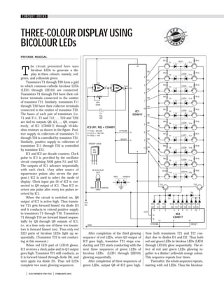
Transistors T1 through T20 form a grid
to which common-cathode bicolour LEDs
(LED1 through LED10) are connected.
Transistors T1 through T10 have their col-
lector terminals connected to the emitter
of transistor T21. Similarly, transistors T11
through T20 have their collector terminals
connected to the emitter of transistor T22.
The bases of each pair of transistors (i.e.
T1 and T11, T2 and T12,…, T10 and T20)
are tied to outputs Q0, Q1,…, Q9, respec-
tively, of IC1 (CD4017) through 10-kilo-
ohm resistors as shown in the figure. Posi-
tive supply to collectors of transistors T1
through T10 is controlled by transistor T21.
Similarly, positive supply to collectors of
transistors T11 through T20 is controlled
by transistor T22.
IC1 and IC2 are decade counters. Clock
pulse to IC1 is provided by the oscillator
circuit comprising NOR gates N1 and N2.
The outputs of IC1 advance sequentially
with each clock. (Any other source of
squarewave pulses also serves the pur-
pose.) IC2 is used to select the mode of
display. Clock input pin 14 of IC2 is con-
nected to Q9 output of IC1. Thus IC2 re-
ceives one pulse after every ten pulses re-
ceived by IC1.
When the circuit is switched on, Q0
output of IC2 is active high. Thus transis-
tor T21 gets forward biased via diode D3
and it conducts to extend positive supply
to transistors T1 through T10. Transistors
T1 through T10 are forward biased sequen-
tially by Q0 through Q9 outputs of IC1,
i.e. at a time only one of these ten transis-
tors is forward biased (on). Thus only red
LED parts of bicolour LEDs light up se- After completion of the third glowing Now both transistors T21 and T22 con-
quentially. (Transistor T22 is not conduct- sequence of red LEDs, when Q3 output of duct due to diodes D1 and D2. Thus both
ing at this moment.) IC2 goes high, transistor T21 stops con- red and green LEDs in bicolour LEDs (LED1
When red LED part of LED10 glows, ducting and T22 starts conducting with the through LED10) glow sequentially. The ef-
IC2 receives a clock pulse and its Q1 output next three sequences of green LEDs of fect of red and green LEDs glowing to-
goes high. Transistor T21 still conducts, as bicolour LEDs (LED1 through LED10) gether is a distinct yellowish orange colour.
it is forward biased through diode D6, and glowing sequentially. This sequence repeats four times.
next again via diode D5. Thus red LEDs After completion of three sequences of Thereafter, the whole sequence repeats,
complete two more glowing sequences. green LEDs, output Q6 of IC2 goes high. starting with red LEDs. Thus the bicolour-
ELECTRONICS FOR YOU FEBRUARY 2003
2. CIRCUIT IDEAS
LED display shows three colours—red, green, by preset VR1. One can omit automatic 5, and 7 of IC2 with SPDT switches. (Thus
and yellowish green—one after the other. selection of different colours by omitting diodes D3-D12 are also omitted.)
The speed of display can be controlled IC2 and replacing connections to pins 3, This circuit costs around Rs 250.
FEBRUARY 2003 ELECTRONICS FOR YOU