
Recommended
Recommended
More Related Content
Similar to John deere 17 zts compact excavator service repair technical manual (tm1897)
Similar to John deere 17 zts compact excavator service repair technical manual (tm1897) (20)
More from ufjkskefmsmerty
More from ufjkskefmsmerty (20)
Recently uploaded
Recently uploaded (20)
John deere 17 zts compact excavator service repair technical manual (tm1897)
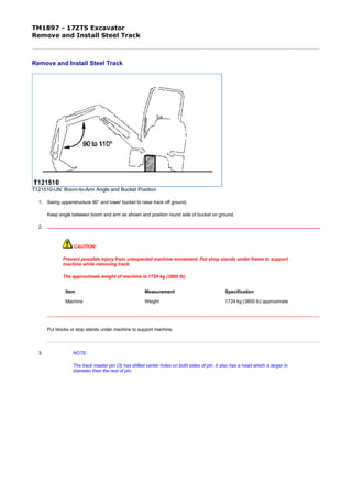
- 1. TM1897 - 17ZTS Excavator Remove and Install Steel Track Remove and Install Steel Track T121510-UN: Boom-to-Arm Angle and Bucket Position 1. Swing upperstructure 90° and lower bucket to raise track off ground. Keep angle between boom and arm as shown and position round side of bucket on ground. 2. CAUTION: Prevent possible injury from unexpected machine movement. Put shop stands under frame to support machine while removing track. The approximate weight of machine is 1724 kg (3800 lb). Put blocks or stop stands under machine to support machine. 3. NOTE: The track master pin (3) has drilled center holes on both sides of pin. It also has a head which is larger in diameter then the rest of pin. Item Measurement Specification Machine Weight 1724 kg (3800 lb) approximate 1/3 2019/11/17file:///C:/ProgramData/Service%20ADVISOR/Temp/TM1897_TXOUOE011...
- 2. T121512-UN: Track Adjuster Valve T126555-UN: Track Master Pin LEGEND: 1 - Track Adjuster Valve 2 - Grease Fitting 3 - Track Master Pin Rotate sprocket to position master pin (3) over front idler. 4. CAUTION: High pressure grease is in track adjuster cylinder. Do not loosen track adjuster valve (1) quickly or too much. High pressure grease may cause serious injury. Never loosen grease fitting (2) to release grease. IMPORTANT: If gravel or mud is packed between sprocket and track, it must be removed before loosening track. Loosen track adjuster valve (1) slowly to discharge grease. Allow track to lower completely. 2/3 2019/11/17file:///C:/ProgramData/Service%20ADVISOR/Temp/TM1897_TXOUOE011...
- 3. 5. CAUTION: The approximate weight of steel track is 136 kg (300 lb). Put wooden blocks in front of front idler and under track to prevent track from falling when master pin is removed. 6. Remove master pin (3). 7. Slowly turn sprocket in reverse direction to remove track from machine. 8. Repair or replace as necessary. 9. Position track on ground beneath front idler and sprocket. 10. Install end of track on sprocket teeth and slowly turn sprocket in forward direction to pull track across top of track frame to front idler. 11. Pull ends of track together and install master pin (3). 12. Adjust steel track sag. (See procedure in this group.) Item Measurement Specification Steel Track Steel Track Weight 136 kg (300 lb) approximate OUOE011,0001598-19-2000/09/19 3/3 2019/11/17file:///C:/ProgramData/Service%20ADVISOR/Temp/TM1897_TXOUOE011...
- 4. TM1897 - 17ZTS Excavator Adjust Track Sag (Rubber Track) Adjust Track Sag (Rubber Track) T121510-UN: Boom-to-Arm Angle and Bucket Position -: Specifications -: Service Equipment and Tools -: Other Material 1. Swing upperstructure 90° and lower bucket to raise track off ground. Keep angle between boom and arm as shown and position round side of bucket on ground. 2. CAUTION: Prevent possible injury from unexpected machine movement. Put shop stands under frame to support machine while adjusting track sag. The approximate weight of machine is 1724 kg (3800 lb). SPECIFICATIONS Track Sag (Rubber Track) Machine Weight 1724 kg (3800 lb) approximate Track Adjuster Torque 88 N·m (65 lb-ft) Rubber Track Sag 10-15 mm (0.4-0.6 in.) SERVICE EQUIPMENT AND TOOLS Grease Gun OTHER MATERIAL Multi-Purpose Grease Item Measurement Specification Machine Weight 1724 kg (3800 lb) approximate 1/3 2019/11/17file:///C:/ProgramData/Service%20ADVISOR/Temp/TM1897_TXOUOE011...
- 5. Put blocks or shop stands under the machine to support. 3. IMPORTANT: If gravel or mud is packed between sprocket and track, it must be removed before adjusting track. T121597-UN: Track Adjuster Valve and Grease Fitting T121598-19: Position Track with Joint Section 2/3 2019/11/17file:///C:/ProgramData/Service%20ADVISOR/Temp/TM1897_TXOUOE011...
- 6. T121599-UN: Measure Rubber Track Sag LEGEND: 1 - Track Adjuster Valve 2 - Grease Fitting 3 - Lower Roller 4 - Track Sag Tighten track adjuster valve (1). Add grease through fitting (2) until most slack is removed from track. 4. Position track with joint section placed just under center lower roller (3) as shown. 5. Measure track sag (4) from lower roller (3) to track. 6. CAUTION: High pressure grease is in track adjuster cylinder. Do not loosen track adjuster valve (1) quickly or too much. Never loosen grease fitting (2) to release grease. IMPORTANT: Prevent possible damage to track components. Do not use the grease fitting on track adjuster cylinder for lubrication. Use grease fitting only for track sag adjustment. To decrease track sag, add grease to track adjuster cylinder through grease fitting. To increase track sag, loosen track adjuster valve to release grease from track adjuster cylinder. Tighten track adjuster valve when track sag is correct. Item Measurement Specification Track Sag (Rubber Track) Track Adjuster Torque 88 N·m (65 lb-ft) Rubber Track Sag 10-15 mm (0.4-0.6 in.) OUOE011,0001599-19-2000/09/19 3/3 2019/11/17file:///C:/ProgramData/Service%20ADVISOR/Temp/TM1897_TXOUOE011...
- 7. TM1897 - 17ZTS Excavator Adjust Track Sag (Steel Track) Adjust Track Sag (Steel Track) T121510-UN: Boom-to-Arm Angle and Bucket Position -: Specifications -: Service Equipment and Tools -: Other Material 1. Swing upperstructure 90° and lower bucket to raise track off ground. Keep angle between boom and arm as shown and position round side of bucket on ground. 2. CAUTION: Prevent possible injury from unexpected machine movement. Put shop stands under frame to support machine while adjusting track sag. The approximate weight of machine is 1724 kg (3800 lb). SPECIFICATIONS Track Sag (Steel Track) Machine Weight 1724 kg (3800 lb) approximate Track Adjuster Torque 88 N·m (65 lb-ft) Steel Track Sag 85-100 mm (3.3-3.9 in.) SERVICE EQUIPMENT AND TOOLS Grease Gun OTHER MATERIAL Multi-Purpose Grease Item Measurement Specification Machine Weight 1724 kg (3800 lb) approximate 1/3 2019/11/17file:///C:/ProgramData/Service%20ADVISOR/Temp/TM1897_TXOUOE011...
- 8. Put blocks or shop stands under the machine to support. 3. IMPORTANT: If gravel or mud is packed between sprocket and track, it must be removed before adjusting track. T121597-UN: Track Adjuster Valve and Grease Fitting T121609-UN: Measure Rubber Track Sag LEGEND: 1 - Track Adjuster Valve 2 - Grease Fitting 3 - Track Sag Slowly turn track forward for two revolutions, then in reverse for two revolutions. Stop track while moving in reverse direction so all track sag is at bottom. 4. Measure track sag (3) at middle track roller from bottom of track frame to top surface of track shoe. 5. CAUTION: High pressure grease is in track adjuster cylinder. Do not loosen track adjuster valve (1) quickly or too much. Never loosen grease fitting (2) to release grease. IMPORTANT: Make sure track adjuster valve is tight. Prevent possible damage to track components. Do not use the grease fitting on track adjuster cylinder for lubrication. 2/3 2019/11/17file:///C:/ProgramData/Service%20ADVISOR/Temp/TM1897_TXOUOE011...
- 9. Use grease fitting only for track sag adjustment. To decrease track sag, add grease to grease fitting. To increase track sag, loosen track adjuster valve to release grease from track adjuster cylinder. Tighten track adjuster valve when track sag is correct. Item Measurement Specification Track Sag (Steel Track) Track Adjuster Torque 88 N·m (65 lb-ft) Steel Track Sag 85-100 mm (3.3-3.9 in.) OUOE011,000159A-19-2000/09/19 3/3 2019/11/17file:///C:/ProgramData/Service%20ADVISOR/Temp/TM1897_TXOUOE011...
- 10. TM1897 - 17ZTS Excavator Remove and Install Sprocket Remove and Install Sprocket T126423-UN: Sprocket LEGEND: 1 - Cap Screw (9 used) 2 - Lock Washer (9 used) 3 - Sprocket 1. Remove track. (See procedure in this group.) 2. Remove cap screws (1) and lock washers (2). 3. Remove sprocket (3). 4. Repair or replace parts as necessary. 5. Install sprocket (3), cap screws (1), and lock washers (2). Tighten cap screws. 6. Install track. (See procedure in this group.) Item Measurement Specification Sprocket Cap Screw Torque 64 N·m (47 lb-ft) OUOE011,000159B-19-2000/09/19 1/1 2019/11/17file:///C:/ProgramData/Service%20ADVISOR/Temp/TM1897_TXOUOE011...
- 11. TM1897 - 17ZTS Excavator Measure Front Idler Wear Measure Front Idler Wear T121638-UN: Front Idler LEGEND: 1 - Front Idler Diameter 2 - Guide Width -: Specifications -: Service Equipment and Tools Measure front idler diameter (1) and guide width (2). SPECIFICATIONS Front Idler Front Idler Diameter 228 mm (8.98 in.) new Front Idler Diameter 222 mm (8.74 in.) allowable limit Guide Width 24 mm (0.94 in.) new Guide Width 18 mm (0.71 in.) allowable limit SERVICE EQUIPMENT AND TOOLS [JT05521Tools are available in a kit such as the JT05518A or JT05523 Undercarriage Inspection Service Tool Kit.] Depth Gauge (200 mm Ruler) [JT05534Tools are available in a kit such as the JT05518A or JT05523 Undercarriage Inspection Service Tool Kit.] Right Angle Attachment Item Measurement Specification Front Idler Front Idler Diameter 228 mm (8.98 in.) new 1/2 2019/11/17file:///C:/ProgramData/Service%20ADVISOR/Temp/TM1897_TXOUOE011...
- 12. Diameter 222 mm (8.74 in.) allowable limit Guide Width 24 mm (0.94 in.) new Width 18 mm (0.71 in.) allowable limit OUOE011,000159C-19-2000/09/19 2/2 2019/11/17file:///C:/ProgramData/Service%20ADVISOR/Temp/TM1897_TXOUOE011...
- 13. TM1897 - 17ZTS Excavator Remove and Install Front Idler Remove and Install Front Idler T121683-UN: Front Idler on Track Frame T121684-UN: Front Idler Removed from Track Frame 1. Remove track. (See procedure in this group.) 2. CAUTION: The approximate weight of front idler is 14.0 kg (30 lb). Using a shop hoist, remove front idler from track frame. 3. Repair or replace as necessary. Item Measurement Specification Front Idler Front Idler Weight 14.0 kg (30 lb) approximate 1/2 2019/11/17file:///C:/ProgramData/Service%20ADVISOR/Temp/TM1897_TXOUOE011...
- 14. 4. Apply grease to sliding surfaces inside track frame. 5. Install front idler into track frame. 6. Install track. (See procedure in this group.) OUOE011,000159D-19-2000/09/19 2/2 2019/11/17file:///C:/ProgramData/Service%20ADVISOR/Temp/TM1897_TXOUOE011...
- 15. TM1897 - 17ZTS Excavator Disassemble and Assemble Front Idler Disassemble and Assemble Front Idler T121616-UN: Front Idler Components LEGEND: 1 - Spring Pin (2 used) 2 - Seal (2 used) 3 - O-Ring (2 used) 4 - Axle 5 - Bushing (2 used) 6 - Idler 7 - Yoke (2 used) 8 - Cap Screw (4 used) 9 - Plate 1. IMPORTANT: Metal face seals can be reused if they are not worn or damaged. A used seal must be kept together as a set because of wear pattern on seal ring face. Inspect metal face seals. (See procedure in this group.) 2. Measure axle and bushings for wear or defects. (See specification for new and allowable limit of wear.) 3. NOTE: Remove bushings only if replacement is necessary. Remove bushing using a 2-jaw puller and adapter from 17-1/2 and 30-ton puller set. 4. Apply a thin film of oil on bushings. If removed, install bushings with flange tight against shoulder of idler. 5. IMPORTANT: O-rings and O-ring grooves must be clean, dry and free of oil to prevent O-rings from slipping when idler is turning. Apply a thin layer of NEVER-SEEZ® Anti-Seize Lubricant or equivalent to both ends of axle from O-ring grooves, bore of yokes, and spring pins. Item Measurement Specification Front Idler Axle OD 25.0 mm (0.98 in.) new OD 24.2 mm (0.95 in.) allowable limit Bushing ID 25.0 mm (0.98 in.) new ID 25.5 mm (1.00 in.) allowable limit Thickness 2 mm (0.08 in.) new flange Thickness 1.5 mm (0.06 in.) allowable limit of flange 1/2 2019/11/17file:///C:/ProgramData/Service%20ADVISOR/Temp/TM1897_TXOUOE011...
- 16. Thank you very much for your reading. Please Click Here. Then Get COMPLETE MANUAL. NO WAITING NOTE: If there is no response to click on the link above, please download the PDF document first and then click on it.
- 17. 6. Assemble and tighten cap screws. Item Measurement Specification Front Idler Yoke Cap Screw Torque 49 N·m (36 lb-ft) NEVER-SEEZ is a trademark of Emhart Chemical Group. OUOE011,000159E-19-2000/09/19 2/2 2019/11/17file:///C:/ProgramData/Service%20ADVISOR/Temp/TM1897_TXOUOE011...
- 18. TM1897 - 17ZTS Excavator Test Front Idler for Oil Leakage Test Front Idler for Oil Leakage T109791B-UN: Test Front Idler LEGEND: A - Plug, Barbed Adapter and Connector B - Connector 1/8 M NPT x 7/16-20 M 37° C - Hose D - Pressure Gauge E - Snubber (Needle) Valve F - Air Pressure Regulator G - Drain Plug 1. Turn shaft several turns to seat metal face seals. 2. Remove plug (G). 3. Install parts (A-F) as shown. Plug, barbed adapter, and connector are from a leak detector kit such as the D05361ST Rubber Stopper/Leak Detector Kit. 4. Holding plug so it is not pushed out, slowly pressurize oil cavity using air. Item Measurement Specification 1/2 2019/11/17file:///C:/ProgramData/Service%20ADVISOR/Temp/TM1897_TXOUOE011...
- 19. 5. Close valve and wait for a minimum of 30 seconds to check for oil leakage. Check gauge to see if air pressure has decreased. 6. If there is external leakage, disassemble idler and replace parts as necessary. 7. Check oil level in idler. If oil level is down and there is no external leakage, check for a leak from oil cavity to interior of idler wheel. 8. Apply cure primer to threads of plug. 9. Apply pipe sealant with to threads of plug. Install and tighten plug. Front Idler Oil Cavity Leakage Test Pressure 110 ± 28 kPa (1.1 ± 0.3 bar) (16 ± 4 psi) LOCTITE is a trademark of Loctite Corp. CED,OUOE011,5065-19-1999/10/19 2/2 2019/11/17file:///C:/ProgramData/Service%20ADVISOR/Temp/TM1897_TXOUOE011...