
Recommended
Recommended
More Related Content
Similar to 35G Excavator Sprocket Remove and Install
Similar to 35G Excavator Sprocket Remove and Install (16)
More from ufjjsjefkksemm
More from ufjjsjefkksemm (20)
Recently uploaded
Recently uploaded (20)
35G Excavator Sprocket Remove and Install
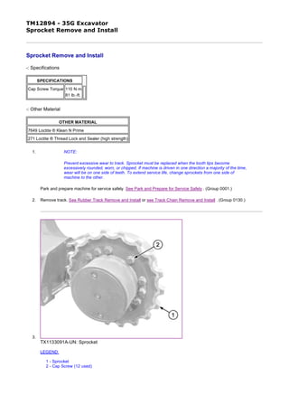
- 1. TM12894 - 35G Excavator Sprocket Remove and Install Sprocket Remove and Install -: Specifications -: Other Material 1. NOTE: Prevent excessive wear to track. Sprocket must be replaced when the tooth tips become excessively rounded, worn, or chipped. If machine is driven in one direction a majority of the time, wear will be on one side of teeth. To extend service life, change sprockets from one side of machine to the other. Park and prepare machine for service safely. See Park and Prepare for Service Safely . (Group 0001.) 2. Remove track. See Rubber Track Remove and Install or see Track Chain Remove and Install . (Group 0130.) 3. TX1133091A-UN: Sprocket LEGEND: 1 - Sprocket 2 - Cap Screw (12 used) SPECIFICATIONS Cap Screw Torque 110 N·m 81 lb.-ft. OTHER MATERIAL 7649 Loctite ® Klean N Prime 271 Loctite ® Thread Lock and Sealer (high strength) 1/2 2019/11/19file:///C:/ProgramData/Service%20ADVISOR/Temp/TM12894_09001faa81f...
- 2. Remove cap screws (2) and sprocket (1). 4. Repair or replace as necessary. 5. Apply PM37509 Klean N Prime and PM37421 Thread Lock and Sealer (high strength) to threads of cap screws. 6. Install sprocket. 7. Install cap screws and tighten to specification. 8. Install track. See Rubber Track Remove and Install or see Track Chain Remove and Install . (Group 0130.) Item Measurement Specification Cap Screw Torque 110 N·m 81 lb.-ft. Loctite is a trademark of Henkel Corporation JS20420,0000971-19-20130403 2/2 2019/11/19file:///C:/ProgramData/Service%20ADVISOR/Temp/TM12894_09001faa81f...
- 3. TM12894 - 35G Excavator Front Idler Remove and Install Front Idler Remove and Install -: Specifications 1. Park and prepare machine for service safely. See Park and Prepare for Service Safely . (Group 0001.) 2. Remove track. See Rubber Track Remove and Install or see Track Chain Remove and Install . (Group 0130.) 3. CAUTION: Prevent possible crushing injury from heavy component. Use appropriate lifting device. TX1132778A-UN: Front Idler LEGEND: 1 - Front Idler 2 - Track Frame Attach appropriate lifting device to support front idler (1). 4. Remove front idler from track frame (2). 5. Measure front idler wear. See 35G Front Idler Flange Height . (SP326VOL1 Undercarriage Appraisal Manual.) SPECIFICATIONS Front Idler Weight (approximate) 26 kg 58 lb. Item Measurement Specification Front Idler Weight (approximate) 26 kg 58 lb. 1/2 2019/11/19file:///C:/ProgramData/Service%20ADVISOR/Temp/TM12894_09001faa81f...
- 4. 6. Repair or replace as necessary. See Front Idler Disassemble and Assemble . (Group 0130.) 7. CAUTION: Prevent possible crushing injury from heavy component. Use appropriate lifting device. Using an appropriate lifting device, install front idler. 8. Install track. See Rubber Track Remove and Install or see Track Chain Remove and Install . (Group 0130.) 9. Adjust track tension. See Check Track Sag—Rubber Track . (Operator’s Manual.) Item Measurement Specification Front Idler Weight (approximate) 26 kg 58 lb. JS20420,0000972-19-20130517 2/2 2019/11/19file:///C:/ProgramData/Service%20ADVISOR/Temp/TM12894_09001faa81f...
- 5. TM12894 - 35G Excavator Front Idler Disassemble and Assemble Front Idler Disassemble and Assemble -: Specifications -: Other Material 1. CAUTION: Prevent possible crushing injury from heavy component. Use appropriate lifting device. TX1134410-UN: Front Idler LEGEND: 1 - Cap Screw (2 used) 2 - Washer (2 used) 3 - Metal Face Seal (2 used) 4 - O-Ring (2 used) 5 - Axle 6 - Bushing (2 used) 7 - Idler 8 - Yoke (2 used) 9 - Cap Screw (4 used) 10 - Plate Remove front idler using appropriate lifting device. See Front Idler Remove and Install . (Group 0130.) 2. Remove cap screws (9) and plate (10). 3. Remove cap screws (1), washers (2), and yokes (8). 4. NOTE: SPECIFICATIONS Front Idler Weight (approximate) 26 kg 58 lb. Yoke-to-Axle Cap Screw Torque 65 N·m 47 lb.-ft. Yoke-to-Plate Cap Screw Torque 90 N·m 66 lb.-ft. OTHER MATERIAL NEVER-SEEZ ® Anti-Seize Lubricant 271 Loctite ® Thread Lock and Sealer (high strength) Item Measurement Specification Front Idler Weight (approximate) 26 kg 58 lb. 1/3 2019/11/19file:///C:/ProgramData/Service%20ADVISOR/Temp/TM12894_09001faa81f...
- 6. Metal face seals (3) can be reused if they are not worn or damaged. A used seal must be kept together as a set because of wear patterns on seal ring face. For seals that are reused, use a piece of cardboard between seal rings to protect seal face. Remove metal face seals (3). Keep seal rings together as a matched set with seal ring faces together to protect surfaces. 5. Inspect metal face seals. See Inspect Metal Face Seals . (Group 0130.) 6. Remove O-rings (4) and axle (5). 7. NOTE: Bushings (6) can not be repaired if worn or damaged, do not remove unless necessary. Inspect bushings (6). Replace bushings if worn or damaged. 8. Inspect and replace parts as necessary. See 35G Front Idler Flange Height . (SP326VOL1 Undercarriage Appraisal Manual.) 9. IMPORTANT: To prevent seizing, apply clean engine oil to parts before assembling. Apply a thin film of engine oil to bushings. Install bushings so flange is tight against shoulder of idler (7). 10. Wipe fingerprints and foreign material off seal face using clean oil and lint-free tissues. Apply a thin film of engine oil to each metal face seal surface. 11. IMPORTANT: Prevent possible machine damage due to improper seal. Face seal O-rings and seat surfaces for O-rings must be clean, dry, and oil free so O-rings do not slip when idler is turning. Seat O-rings properly. NOTE: A volatile, non-petroleum base solvent or talcum powder may be used as a lubricant. Thoroughly clean O-rings and seat surfaces using volatile, non-petroleum base solvent and lint-free tissues. 12. NOTE: Repeat procedure for opposite side. Install metal face seal in yoke. Apply equal pressure with fingers at four equally spaced points on seal face. Metal face seal must “pop” down into place so O-ring is tight against seal bore. 13. NOTE: Repeat procedure for opposite side. Install metal face seal in idler. Apply equal pressure with fingers at four equally spaced points on seal face. Metal face seal must “pop” down into place so O-ring is tight against seal bore. 14. Wipe fingerprints and foreign material off seal face using clean oil and lint-free tissues. Apply a thin film of engine oil to each seal ring face. 15. Install axle and O-rings. 16. Apply a thin layer of TY24811 NEVER-SEEZ ® Anti-Seize Lubricant to end of one side of axle from O-ring grooves to bore of yoke. 17. Install one yoke on axle. 18. Apply PM37421 Thread Lock and Sealer (high strength) to threads of cap screw (1). Install washer (2) and cap screw (1) to yoke and tighten to specification. Item Measurement Specification Yoke-to-Axle Cap Screw Torque 65 N·m 47 lb.-ft. 2/3 2019/11/19file:///C:/ProgramData/Service%20ADVISOR/Temp/TM12894_09001faa81f...
- 7. 19. TX1134411-UN: Front Idler Lubrication LEGEND: 5 - Axle 7 - Idler 8 - Yoke Place idler assembly on a work bench with yoke installed side facing down. 20. IMPORTANT: To prevent seizing, apply clean engine oil between idler and axle. Add engine oil between idler (7) and axle (5). 21. Apply a thin layer of TY24811 NEVER-SEEZ ® Anti-Seize Lubricant to end of axle from O-ring grooves to bore of yoke. 22. Install second yoke on axle. 23. Apply PM37421 Thread Lock and Sealer (high strength) to threads of cap screw (1). Install washer (2) and cap screw (1) to yoke and tighten to specification. 24. Install plate and tighten cap screws (9) to specification. 25. CAUTION: Prevent possible crushing injury from heavy component. Use appropriate lifting device. Install front idler using appropriate lifting device. See Front Idler Remove and Install . (Group 0130.) Item Measurement Specification Yoke-to-Axle Cap Screw Torque 65 N·m 47 lb.-ft. Item Measurement Specification Yoke-to-Plate Cap Screw Torque 90 N·m 66 lb.-ft. Item Measurement Specification Front Idler Weight (approximate) 26 kg 58 lb. NEVER-SEEZ is a trademark of Emhart Chemical Group Loctite is a trademark of Henkel Corporation JS20420,0000973-19-20130424 3/3 2019/11/19file:///C:/ProgramData/Service%20ADVISOR/Temp/TM12894_09001faa81f...
- 8. TM12894 - 35G Excavator Track Adjuster and Recoil Spring Remove and Install Track Adjuster and Recoil Spring Remove and Install 1. Park and prepare machine for service safely. See Park and Prepare for Service Safely . (Group 0001.) 2. Remove track. See Rubber Track Remove and Install or see Track Chain Remove and Install . (Group 0130.) 3. Remove front idler. See Front Idler Remove and Install . (Group 0130.) 4. TX1132784A-UN: Track Adjuster and Recoil Spring LEGEND: 1 - Track Adjuster and Recoil Spring 2 - Track Frame Remove track adjuster and recoil spring (1) from track frame (2). 5. Repair or replace parts as necessary. See Track Adjuster and Recoil Spring Disassemble and Assemble . (Group 0130.) 6. Install track adjuster and recoil spring into track frame. 7. Install front idler. See Front Idler Remove and Install . (Group 0130.) 8. Install track. See Rubber Track Remove and Install or see Track Chain Remove and Install . (Group 0130.) JS20420,0000974-19-20130401 1/1 2019/11/19file:///C:/ProgramData/Service%20ADVISOR/Temp/TM12894_09001faa81f...
- 9. TM12894 - 35G Excavator Track Adjuster and Recoil Spring Disassemble and Assemble Track Adjuster and Recoil Spring Disassemble and Assemble -: Specifications -: Service Equipment and Tools 1. CAUTION: Prevent possible injury. Recoil spring or rod may break if dropped while handling, transporting, or disassembling. Nicks or weld craters in spring and rod assembly can cause stress concentration resulting in a weak spot. Weak spots may result in immediate or eventual malfunction. Use heavy protective covering around spring assembly when handling, transporting, or disassembling track adjuster. To avoid personal injury from extreme preload on spring, a compression tool must be used for disassembly and assembly. Remove track adjuster and recoil spring. See Track Adjuster and Recoil Spring Remove and Install . (Group 0130.) 2. NOTE: It is not necessary to remove the recoil spring to replace dust seal (17) and U-ring packing (16) on piston rod (18). TX1198783-UN: Track Adjuster and Recoil Spring Assembly LEGEND: 7 - Grease Fitting 8 - Nut SPECIFICATIONS Track Recoil Spring Disassembly and Assembly Tool Weight (approximate) 227 kg 500 lb Rubber Track Compressed Recoil Spring Length 176 mm 6.9 in Steel Track Compressed Recoil Spring Length 198 mm 7.8 in Plug Torque 15 N·m 133 lb·in Track Adjuster Valve Torque 90 N·m 66 lb·ft SERVICE EQUIPMENT AND TOOLS 20-Ton Hydraulic Jack ST4920 [Fabricated tool, dealer made. (See Group 9900 for instructions to make tool.)] Track Recoil Spring Disassembly and Assembly Tool DFT1110 [Fabricated tool, dealer made. (See Group 9900 for instructions to make tool.)] Spacer DFT1087 [Fabricated tool, dealer made. (See Group 9900 for instructions to make tool.)] Track Recoil Spring Disassembly and Assembly Guard Tool 1/8 2019/11/19file:///C:/ProgramData/Service%20ADVISOR/Temp/TM12894_09001faa81f...
- 10. 9 - Plug 12 - Track Adjuster Valve 13 - Retainer Plate 14 - Recoil Spring 15 - Cylinder 16 - U-Ring Packing 17 - Dust Seal 18 - Piston Rod 19 - Hole Position (rubber track) 20 - Hole Position (steel track) Remove piston rod (18). 3. Remove dust seal (17) and U-ring packing (16). 4. CAUTION: Prevent possible crushing injury from heavy component. Use appropriate lifting device. 2/8 2019/11/19file:///C:/ProgramData/Service%20ADVISOR/Temp/TM12894_09001faa81f...
- 11. TX1133214-UN: Track Recoil Spring Tool 3/8 2019/11/19file:///C:/ProgramData/Service%20ADVISOR/Temp/TM12894_09001faa81f...
- 12. TX1133218-UN: Installing Track Adjuster in Disassembly and Assembly Tool LEGEND: 1 - ST4920 Track Recoil Spring Disassembly and Assembly Tool 2 - Nut (8 used) 3 - Top Plate 4 - 20-Ton Hydraulic Jack 5 - Track Adjuster and Recoil Spring 6 - DFT1110 Spacer Place 20-ton hydraulic jack (4) on bottom of ST4920 Track Recoil Spring Disassembly and Assembly Tool (1). See ST4920 Track Recoil Spring Disassembly and Assembly Tool . (Group 9900.) 5. Remove nuts (2) and top plate (3). 6. Extend 20-ton hydraulic jack to provide enough travel to release recoil spring (14). 7. Install DFT1110 Spacer (6) on to ST4920 Track Recoil Spring Disassembly and Assembly Tool. See DFT1110 Spacer . (Group 9900.) 8. Position track adjuster and recoil spring (5) in ST4920 Track Recoil Spring Disassembly and Assembly Tool with cylinder end on DFT1110 Spacer. Item Measurement Specification Track Recoil Spring Disassembly and Assembly Tool Weight (approximate) 227 kg 500 lb 4/8 2019/11/19file:///C:/ProgramData/Service%20ADVISOR/Temp/TM12894_09001faa81f...
- 13. 9. TX1133220-UN: Track Recoil Spring Guard Tool 5/8 2019/11/19file:///C:/ProgramData/Service%20ADVISOR/Temp/TM12894_09001faa81f...
- 14. TX1133223-UN: Track Recoil Spring Guard Tool—Guard Raised LEGEND: 2 - Nut (8 used) 3 - Top Plate 7 - Grease Fitting 8 - Nut 9 - Plug 10 - DFT1087 Track Recoil Spring Disassembly and Assembly Guard Tool 11 - T-Handle (2 used) Install DFT1087 Track Recoil Spring Disassembly and Assembly Guard Tool (10). See DFT1087 Track Recoil Spring Disassembly and Assembly Guard Tool . (Group 9900.) 10. NOTE: The ST4920 Track Recoil Spring Disassembly and Assembly Tool is the same as used on other machines except the top plate. Use the top plate (3) with the smallest opening that allows access to nut (8). Install top plate and nuts (2). 11. Tighten nuts (2) so top plate is tight against retainer plate (13) on track adjuster. 6/8 2019/11/19file:///C:/ProgramData/Service%20ADVISOR/Temp/TM12894_09001faa81f...
- 15. 12. Remove grease fitting (7) and plug (9). 13. Raise upper half of DFT1087 Track Recoil Spring Disassembly and Assembly Guard Tool and tighten T-handles (11). 14. Extend 20-ton hydraulic jack to release pressure on nut (8). 15. Remove nut (8). 16. Lower 20-ton hydraulic jack to release recoil spring tension. 17. Remove nuts (2), top plate, and DFT1087 Track Recoil Spring Disassembly and Assembly Guard Tool. 18. TX1198783-UN: Track Adjuster and Recoil Spring Assembly LEGEND: 7 - Grease Fitting 8 - Nut 9 - Plug 12 - Track Adjuster Valve 13 - Retainer Plate 14 - Recoil Spring 15 - Cylinder 16 - U-Ring Packing 17 - Dust Seal 18 - Piston Rod 19 - Hole Position (rubber track) 20 - Hole Position (steel track) Remove retainer plate (13), recoil spring (14), and track adjuster valve (12). 19. Inspect and replace parts as necessary. 20. Install DFT1110 Spacer on to ST4920 Track Recoil Spring Disassembly and Assembly Tool. 21. Install cylinder into DFT1110 Spacer. 22. Install recoil spring and retainer plate. 23. Install DFT1087 Track Recoil Spring Disassembly and Assembly Guard Tool. 24. Install top plate and nuts (2). 25. Tighten nuts (2) so top plate is tight against retainer plate. 26. Raise upper half of DFT1087 Track Recoil Spring Disassembly and Assembly Guard Tool and tighten T-handles. 27. Extend 20-ton hydraulic jack to compress recoil spring to specification. 28. NOTE: Nut (8) must be positioned correctly for either steel or rubber track. Install nut (8) so threaded hole is aligned with either hole position (19 or 20). Item Measurement Specification Rubber Track Compressed Recoil Spring Length 176 mm 6.9 in Steel Track Compressed Recoil Spring Length 198 mm 7.8 in 7/8 2019/11/19file:///C:/ProgramData/Service%20ADVISOR/Temp/TM12894_09001faa81f...
- 16. 29. Install plug. Tighten plug to specification. 30. Install track adjuster valve to specification. 31. Install and tighten grease fitting. 32. Lower 20-ton hydraulic jack to release recoil spring tension. 33. Remove nuts (2), top plate, and DFT1087 Track Recoil Spring Disassembly and Assembly Guard Tool. 34. Remove track adjuster and recoil spring assembly from ST4920 Track Recoil Spring Disassembly and Assembly Tool. 35. IMPORTANT: To prevent seizing, apply clean hydraulic oil to parts before assembling. Install U-ring packing and dust seal. 36. Apply multipurpose grease to piston rod, U-ring packing, and dust seal. Fill cylinder with grease. 37. Push piston rod into cylinder and completely bleed air from cylinder. 38. Install track adjuster and recoil spring into machine. See Track Adjuster and Recoil Spring Remove and Install . (Group 0130.) Item Measurement Specification Plug Torque 15 N·m 133 lb·in Item Measurement Specification Track Adjuster Valve Torque 90 N·m 66 lb·ft JS20420,000098D-19-20150817 8/8 2019/11/19file:///C:/ProgramData/Service%20ADVISOR/Temp/TM12894_09001faa81f...
- 17. TM12894 - 35G Excavator Travel Gear Case Remove and Install Travel Gear Case Remove and Install -: Specifications NOTE: The travel gear case, travel motor, and park brake are enclosed in the same housing. 1. Park and prepare machine for service safely. See Park and Prepare for Service Safely . (Group 0001.) 2. Remove track. See Rubber Track Remove and Install or see Track Chain Remove and Install . (Group 0130.) 3. CAUTION: Avoid personal injury from high-pressure fluid. High-pressure release of oil from pressurized system can cause serious burns or penetrating injury. Relieve pressure from hydraulic system before disconnecting or connecting hydraulic or other lines. Tighten all connections before applying pressure. Release hydraulic oil tank pressure by loosening hydraulic oil tank fill cap. See Hydraulic Oil Tank Pressure Release Procedure . (Group 9025-25.) 4. Apply vacuum or drain hydraulic oil tank. See Apply Vacuum to Hydraulic Oil Tank . (Group 3360.) See Drain and Refill Hydraulic Tank Oil . (Operator’s Manual.) SPECIFICATIONS Hydraulic Oil Tank Capacity (approximate) 32 L 8.5 gal. Travel Gear Case Assembly Weight (approximate) 48 kg 110 lb. Cap Screw Torque 110 N·m 81 lb.-ft. Item Measurement Specification Hydraulic Oil Tank Capacity (approximate) 32 L 8.5 gal. 1/4 2019/11/19file:///C:/ProgramData/Service%20ADVISOR/Temp/TM12894_09001faa81f...
- 18. 5. TX1132633A-UN: Travel Motor Cover TX1132632A-UN: Travel Motor LEGEND: 1 - Cap Screw (3 used) 2 - Travel Motor Access Panel 3 - Cap Screw (12 used) 4 - Drain Hose 5 - Travel Gear Case Assembly 6 - Travel Forward Hose 7 - Travel Speed Hose 8 - Travel Reverse Hose Remove cap screws (1) and travel motor access panel (2). 6. Install identification tags and disconnect hoses (4 and 6—8). Close all openings using caps and plugs. See Travel Hydraulic System Line Connection . (Group 9025-15.) 7. Apply alignment marks between travel gear case assembly and track frame. 2/4 2019/11/19file:///C:/ProgramData/Service%20ADVISOR/Temp/TM12894_09001faa81f...
- 19. Thank you very much for your reading. Please Click Here. Then Get COMPLETE MANUAL. NO WAITING NOTE: If there is no response to click on the link above, please download the PDF document first and then click on it.
- 20. 8. CAUTION: Prevent possible crushing injury from heavy component. Use appropriate lifting device. NOTE: The travel gear case assembly (5) is shown removed with sprocket for balance. TX1133494A-UN: Travel Gear Case Assembly LEGEND: 5 - Travel Gear Case Assembly 9 - Sprocket Using appropriate lifting device, remove cap screws (3) and travel gear case assembly (5). 9. Remove sprocket (9). See Sprocket Remove and Install . (Group 0130.) 10. Clean, inspect, and replace parts as necessary. See Travel Gear Case Disassemble and Assemble . (Group 0250.) See Travel Motor and Park Brake Disassemble and Assemble . (Group 0260.) See Park Brake Valve Disassemble and Assemble . (Group 0260.) 11. Install sprocket. See Sprocket Remove and Install . (Group 0130.) 12. CAUTION: Item Measurement Specification Travel Gear Case Assembly Weight (approximate) 48 kg 110 lb. 3/4 2019/11/19file:///C:/ProgramData/Service%20ADVISOR/Temp/TM12894_09001faa81f...
- 21. Prevent possible crushing injury from heavy component. Use appropriate lifting device. Using appropriate lifting device, install travel gear case assembly. 13. Align mark on travel gear case assembly to mark on track frame. Install cap screws (3) and tighten to specification. 14. NOTE: Drain hose (4) will remain capped and plugged until travel motor start-up procedure is performed. Connect hydraulic hoses (6—8). See Travel Hydraulic System Line Connection . (Group 9025-15.) 15. Remove vacuum or fill hydraulic oil tank. See Apply Vacuum to Hydraulic Oil Tank . (Group 3360.) See Drain and Refill Hydraulic Tank Oil . (Operator’s Manual.) 16. Perform travel motor start-up procedure and connect drain hose (4). See Travel Motor and Park Brake Start-Up Procedure . (Group 0260.) 17. IMPORTANT: Hydraulic pumps will be damaged if not filled with oil before starting. Procedure must be performed to fill pump housings whenever oil has been drained from the pumps or hydraulic oil tank. If hydraulic oil tank was drained, perform pump start-up procedure. See Hydraulic Pump Start-Up Procedure . (Group 3360.) 18. Check hydraulic oil level. See Check Hydraulic Tank Oil Level . (Operator’s Manual.) 19. Install track. See Rubber Track Remove and Install or see Track Chain Remove and Install . (Group 0130.) 20. Operate machine and check for leaks. 21. Install travel motor access panel and cap screws (1). Item Measurement Specification Travel Gear Case Assembly Weight (approximate) 48 kg 110 lb. Item Measurement Specification Cap Screw Torque 110 N·m 81 lb.-ft. Item Measurement Specification Hydraulic Oil Tank Capacity (approximate) 32 L 8.5 gal. JS20420,0000A21-19-20130520 4/4 2019/11/19file:///C:/ProgramData/Service%20ADVISOR/Temp/TM12894_09001faa81f...
- 22. TM12894 - 35G Excavator Travel Gear Case Disassemble and Assemble Travel Gear Case Disassemble and Assemble Disassemble Travel Gear Case TX1135944-UN: Travel Gear Case LEGEND: 1 - Check Plug 2 - O-Ring 3 - Plug (2 used) 4 - O-Ring (2 used) 5 - Wire Retainer 6 - Cover 7 - O-Ring 8 - Thrust Ring 9 - Input Shaft and First Stage Sun Gear 10 - Snap Ring 11 - First Stage Planetary Carrier 12 - Thrust Washer 13 - Second Stage Sun Gear 14 - Snap Ring (3 used) 15 - Thrust Washer (6 used) 16 - Bearing Pin (3 used) 17 - Needle Bearing (3 used) 18 - First Stage Planetary Gear (3 used) 19 - Spring Pin (3 used) 20 - Snap Ring (4 used) 21 - Thrust Washer (4 used) 22 - Second Stage Planetary Gear (4 used) 23 - Needle Bearing (4 used) 24 - Bearing Race (4 used) 25 - Thrust Washer (4 used) 26 - Snap Ring 1/8 2019/11/19file:///C:/ProgramData/Service%20ADVISOR/Temp/TM12894_09001faa81f...