
Recommended
Recommended
More Related Content
Similar to Caterpillar Cat 943 TRACK LOADER (Prefix 19Z) Service Repair Manual Instant Download (19Z00001-00252).pdf
Similar to Caterpillar Cat 943 TRACK LOADER (Prefix 19Z) Service Repair Manual Instant Download (19Z00001-00252).pdf (20)
More from ti76cui
More from ti76cui (20)
Recently uploaded
Recently uploaded (20)
Caterpillar Cat 943 TRACK LOADER (Prefix 19Z) Service Repair Manual Instant Download (19Z00001-00252).pdf
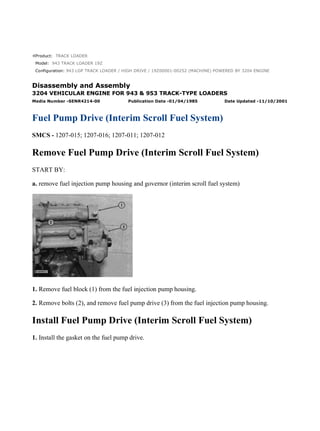
- 1. Product: TRACK LOADER Model: 943 TRACK LOADER 19Z Configuration: 943 LGP TRACK LOADER / HIGH DRIVE / 19Z00001-00252 (MACHINE) POWERED BY 3204 ENGINE Disassembly and Assembly 3204 VEHICULAR ENGINE FOR 943 & 953 TRACK-TYPE LOADERS Media Number -SENR4214-00 Publication Date -01/04/1985 Date Updated -11/10/2001 Fuel Pump Drive (Interim Scroll Fuel System) SMCS - 1207-015; 1207-016; 1207-011; 1207-012 Remove Fuel Pump Drive (Interim Scroll Fuel System) START BY: a. remove fuel injection pump housing and governor (interim scroll fuel system) 1. Remove fuel block (1) from the fuel injection pump housing. 2. Remove bolts (2), and remove fuel pump drive (3) from the fuel injection pump housing. Install Fuel Pump Drive (Interim Scroll Fuel System) 1. Install the gasket on the fuel pump drive. 1/5 943 LGP TRACK LOADER / HIGH DRIVE / 19Z00001-00252 (MACHINE) POWE... 2022/1/10 https://127.0.0.1/sisweb/sisweb/techdoc/techdoc_print_page.jsp?returnurl=/sis...
- 2. NOTE: Groove (slot) (2) in the camshaft of the fuel injection pump is not in the center of the shaft so shaft (1) in the fuel pump drive must be turned to the same position when the pump drive is installed. 2. Install the fuel pump drive on the fuel injection pump housing, and install the bolts that hold it in place. 3. Be sure the O-ring seal is in position on fuel block (3), and put clean oil on the O-ring seal. Install the fuel block in the end of the fuel injection pump housing as shown. END BY: a. install fuel injection pump housing and governor (interim scroll fuel system) Disassemble Fuel Pump Drive (Interim Scroll Fuel System) START BY: a. remove fuel pump drive (interim scroll fuel system) 2/5 943 LGP TRACK LOADER / HIGH DRIVE / 19Z00001-00252 (MACHINE) POWE... 2022/1/10 https://127.0.0.1/sisweb/sisweb/techdoc/techdoc_print_page.jsp?returnurl=/sis...
- 3. 1. Remove fuel transfer pump (1). 2. Use tool (A) to remove snap ring (2). Remove O-ring seal (3). 3. Remove shaft assembly (4) from the housing. 4. Remove shaft (6) from cam (5) with tool (B) and a press. 3/5 943 LGP TRACK LOADER / HIGH DRIVE / 19Z00001-00252 (MACHINE) POWE... 2022/1/10 https://127.0.0.1/sisweb/sisweb/techdoc/techdoc_print_page.jsp?returnurl=/sis...
- 4. 5. Remove bearing (7) from cam (5). Assemble Fuel Pump Drive (Interim Scroll Fuel System) 1. Install bearing (1) on cam (2). 2. Install shaft (3) in cam (2) with a press. 3. Put shaft assembly (4) in position in housing (5). 4/5 943 LGP TRACK LOADER / HIGH DRIVE / 19Z00001-00252 (MACHINE) POWE... 2022/1/10 https://127.0.0.1/sisweb/sisweb/techdoc/techdoc_print_page.jsp?returnurl=/sis...
- 5. 4. Install O-ring seal (7). 5. Use tool (A) to install snap ring (6). 6. Be sure the O-ring seal is in position on fuel transfer pump (8), and put clean oil on the O-ring seal. 7. Put fuel transfer pump (8) in position on the fuel pump drive, and install the three nuts that hold it in place. END BY: a. install fuel pump drive (interim scroll fuel system) 5/5 943 LGP TRACK LOADER / HIGH DRIVE / 19Z00001-00252 (MACHINE) POWE... 2022/1/10 https://127.0.0.1/sisweb/sisweb/techdoc/techdoc_print_page.jsp?returnurl=/sis...
- 6. Product: TRACK LOADER Model: 943 TRACK LOADER 19Z Configuration: 943 LGP TRACK LOADER / HIGH DRIVE / 19Z00001-00252 (MACHINE) POWERED BY 3204 ENGINE Disassembly and Assembly 3204 VEHICULAR ENGINE FOR 943 & 953 TRACK-TYPE LOADERS Media Number -SENR4214-00 Publication Date -01/04/1985 Date Updated -11/10/2001 Governor (Interim Scroll Fuel System) SMCS - 1264-015; 1264-016 Disassemble Governor (Interim Scroll Fuel System) START BY: 1/10 943 LGP TRACK LOADER / HIGH DRIVE / 19Z00001-00252 (MACHINE) POWE... 2022/1/10 https://127.0.0.1/sisweb/sisweb/techdoc/techdoc_print_page.jsp?returnurl=/sis...
- 7. a. remove fuel injection pump housing and governor (interim scroll fuel system) NOTE: If it is desired to only remove the governor so the fuel injection pump housing can be disassembled, do only Steps 1, 3, 5, 6, 12 and 13. 1. Remove cover (1). 2. Remove lever (2) and the key from the shaft. 3. Remove bolts (3) and cover (4) from the governor housing. 4. Remove O-ring seals (5) from the low and high idle adjustment screws. 5. Remove screw (6) from rack stop collar (7), and remove collar (7). Remove the spring from behind the collar. 2/10 943 LGP TRACK LOADER / HIGH DRIVE / 19Z00001-00252 (MACHINE) POWE... 2022/1/10 https://127.0.0.1/sisweb/sisweb/techdoc/techdoc_print_page.jsp?returnurl=/sis...
- 8. 6. Remove bolts (8), and remove governor housing (9) from the fuel injection pump housing. 7. Remove high idle adjustment screw (11) and low idle adjustment screw (10) from the governor housing. Remove the high idle adjustment screw first. 8. Remove bolts (12) and torque control (13) from the governor housing. 9. Remove bolt (14) and the lock. Remove shaft (15) and lever assembly (16) from the governor housing. Pin (19) holds spring (17) in compression. Use caution to prevent injury when pin (19) is removed. Release the tension in spring (17) slowly. 3/10 943 LGP TRACK LOADER / HIGH DRIVE / 19Z00001-00252 (MACHINE) POWE... 2022/1/10 https://127.0.0.1/sisweb/sisweb/techdoc/techdoc_print_page.jsp?returnurl=/sis...
- 9. 10. Remove pin (19), spring (17) and plunger (18) from the lever assembly. 11. Remove seal (21) from the governor housing. Use tooling (A) to remove the plug and bearings (20) from the governor housing. NOTE: If a replacement of spring guide (22) is necessary, see Special Instruction, Form No. SMHS7356 - Use Of 6V22 Tool Group For Replacement Of Governor Spring Guide. 12. Remove seat, washer, wave-washers and governor spring (23) from the weight assembly. Remove spring washer (26) from the weight assembly. 13. Remove bolts (24) and the lock that hold weight assembly (25) to the fuel injection pump housing. Pull the weight assembly out and to the side to disengage it from the rack. 14. Remove ring (27) and the dowel under the ring that holds seat (28) in place. 4/10 943 LGP TRACK LOADER / HIGH DRIVE / 19Z00001-00252 (MACHINE) POWE... 2022/1/10 https://127.0.0.1/sisweb/sisweb/techdoc/techdoc_print_page.jsp?returnurl=/sis...
- 10. 15. Remove seat (28), bolt (29) and spring (30) from the weight assembly. Remove washer (31) from spring (30). 16. Remove guide (32), the two races and bearing from the sleeve. 17. Remove the second dowel (33) that holds sleeve (34) in place, and remove the sleeve. 18. Remove valve (37) from the weight assembly and cylinder (35). 19. Remove lock (36), and separate the weight assembly and cylinder (35). 20. Remove sleeve (38) and piston (39) from cylinder (35). Remove the O-ring seal from the sleeve. Assemble Governor (Interim Scroll Fuel System) 5/10 943 LGP TRACK LOADER / HIGH DRIVE / 19Z00001-00252 (MACHINE) POWE... 2022/1/10 https://127.0.0.1/sisweb/sisweb/techdoc/techdoc_print_page.jsp?returnurl=/sis...
- 11. NOTE: Put clean oil on all parts before assembly and be sure all oil passages are clear. 1. Install the O-ring seal on sleeve (2). Install piston (1) in sleeve (2). Install sleeve (2) in cylinder (3). 2. Install cylinder (3) in weight assembly (4), and install lock (5) to hold them together. 3. Install valve (7) through the cylinder, and install sleeve (6) on the valve with the second hole in the sleeve in alignment with the hole in the valve. Install dowel (8) to hold the sleeve on the valve. 6/10 943 LGP TRACK LOADER / HIGH DRIVE / 19Z00001-00252 (MACHINE) POWE... 2022/1/10 https://127.0.0.1/sisweb/sisweb/techdoc/techdoc_print_page.jsp?returnurl=/sis...
- 12. 4. Install larger race (9), bearing (10), smaller race (11) and guide (12) on sleeve (8). Put the hole in guide (12) in alignment with the first hole in sleeve (8). 5. Install washer (16) in spring (13). Install bolt (17) in seat (14). Put spring (13) and seat (14) in position on guide (12) with the hole in seat (14) in alignment with the hole in guide (12). Install dowel (18) through seat (14) and guide (12). Install ring (15) on the seat to hold the dowel in place. 6. Install the weight assembly on the fuel injection pump housing with piston (1) engaged over the groove in rack (19). Install lock (20) and the bolts that hold the weight assembly to the fuel injection pump housing. 7. Install spring washer (26) on the bolt as shown. 8. Install spring (25), one wave washer (24), flat washer (23), other wave washer (22) and seat (21) on the bolt as shown. 7/10 943 LGP TRACK LOADER / HIGH DRIVE / 19Z00001-00252 (MACHINE) POWE... 2022/1/10 https://127.0.0.1/sisweb/sisweb/techdoc/techdoc_print_page.jsp?returnurl=/sis...
- 13. 9. Put plunger (28) and spring (27) in position in lever assembly (30), and install pin (29) to hold the spring and plunger in place. 10. Dimensions (X) and (Y) are controlled by the depths of bearings (32) and (33) in the governor housing. Install bearings (32) and (33) with tooling (A). Install lever assembly (30) and shaft (31) in the governor housing. With lever assembly (30) pushed against bearing (33) on the detent side, the clearance [dimension (Y)] between the guide for the governor spring and lever assembly (30) must be approximately 2.49 mm (.098 in.). Push lever assembly (30) against bearing (32) on the other side. The clearance [dimension (X)] between the guide for the governor spring and lever assembly must be approximately 3.40 mm (.134 in.). If the measurements are not correct, remove the lever assembly and the shaft, and move the bearings as necessary to get the correct measurement. After the bearings are installed, there must be approximately .38 mm (.015 in.) end play in the lever assembly. Remove the shaft and lever assembly. 11. Install the plug on the detent side of the governor housing with tooling (A) to a depth of 2.30 ± 0.5 mm (.091 ± 0.20 in.). Install the lip-type seal in the opposite side of the governor housing with tooling (A). Install the lip-type seal with the lip toward the inside of the governor housing. 12. Put the lever assembly and shaft in position in the governor housing, and install the bolt and lock in the lever assembly. 13. Assemble the torque control group as follows: a. Install lock (35), retainer (36), insulator (37) and retainer (38) on bolts (34) as shown. b. Install contact (39) on bolts (34) as shown. 8/10 943 LGP TRACK LOADER / HIGH DRIVE / 19Z00001-00252 (MACHINE) POWE... 2022/1/10 https://127.0.0.1/sisweb/sisweb/techdoc/techdoc_print_page.jsp?returnurl=/sis...
- 14. c. Install spring (40), spacer (41), shim (42), bar (43) and insulator (44) on bolts (34) as shown. 14. Install torque control group (45) on the governor housing as shown. Bend the lock to hold the bolts tight. 15. Install low idle adjustment screw (46) first; then high idle adjustment screw (47) in the governor housing. 16. Put the gasket and governor housing (48) in position on the fuel injection pump housing with bolt (17) and the spring seat in alignment with the spring guide in the governor housing. Install the bolts that hold the governor housing to the fuel injection pump housing. 9/10 943 LGP TRACK LOADER / HIGH DRIVE / 19Z00001-00252 (MACHINE) POWE... 2022/1/10 https://127.0.0.1/sisweb/sisweb/techdoc/techdoc_print_page.jsp?returnurl=/sis...
- 15. 17. Install O-ring seal (49) on the low and high idle adjustment screws. 18. Put spring (50) and rack stop collar (51) in position on the bolt in the weight assembly, and install the allen screw that holds the rack stop collar in place. 19. Put the gasket and cover in position on the governor housing with dowel (52) in the cover in alignment with notch (53) in the rack stop collar. Install the bolts that hold the cover in place. 20. Install the gasket and cover (54) over the low and high idle adjustment screws. 21. Install the key and lever on shaft (31). 22. After installation of the fuel injection pump housing and governor, adjust the rack and governor. See Fuel Rack Setting And Governor Adjustments in Testing And Adjusting. END BY: a. install fuel injection pump housing and governor (interim scroll fuel system) 10/10 943 LGP TRACK LOADER / HIGH DRIVE / 19Z00001-00252 (MACHINE) PO... 2022/1/10 https://127.0.0.1/sisweb/sisweb/techdoc/techdoc_print_page.jsp?returnurl=/sis...
- 16. Product: TRACK LOADER Model: 943 TRACK LOADER 19Z Configuration: 943 LGP TRACK LOADER / HIGH DRIVE / 19Z00001-00252 (MACHINE) POWERED BY 3204 ENGINE Disassembly and Assembly 3204 VEHICULAR ENGINE FOR 943 & 953 TRACK-TYPE LOADERS Media Number -SENR4214-00 Publication Date -01/04/1985 Date Updated -11/10/2001 Governor (New Scroll Fuel System Effective In Production With 10X5411-Up, 45V36536-Up) SMCS - 1264-015; 1264-016 1/19 943 LGP TRACK LOADER / HIGH DRIVE / 19Z00001-00252 (MACHINE) POWE... 2022/1/10 https://127.0.0.1/sisweb/sisweb/techdoc/techdoc_print_page.jsp?returnurl=/sis...
- 17. Disassemble Governor (New Scroll Fuel System Effective In Production With 10X5411-Up, 45V36536-Up) START BY: a. remove fuel injection pump housing and governor (new scroll fuel system effective in production with 10X5411-UP, 45V36536-UP) b. remove fuel transfer pump (new scroll fuel system effective in production with 10X5411-UP, 45V36536-UP) NOTE: If it is desired to remove only the governor so the fuel injection pump housing can be disassembled, do only Steps 1, 2, 15, 21, 25, 26, 27, 28, 31, 33, 34 and 37. 1. Remove bolts (1) and cover (2). 2/19 943 LGP TRACK LOADER / HIGH DRIVE / 19Z00001-00252 (MACHINE) POWE... 2022/1/10 https://127.0.0.1/sisweb/sisweb/techdoc/techdoc_print_page.jsp?returnurl=/sis...
- 18. 2. Remove six bolts (3), two top bolts (4), housing (5) and the gasket. 3. Remove governor spring (6), the two wave washers, one flatwasher and seat from the guide in the housing. 4. Make a mark of the position of lever (7) on shaft (8). Loosen bolt (10). Use a chisel or screwdriver to expand expansion of lever (7) so it can be removed from shaft (8). 5. Remove cover assembly (9). 6. Use tooling (A) to remove seal (10) from cover (9). 7. Remove low idle adjustment screw (12) and spring (11) from the housing. 3/19 943 LGP TRACK LOADER / HIGH DRIVE / 19Z00001-00252 (MACHINE) POWE... 2022/1/10 https://127.0.0.1/sisweb/sisweb/techdoc/techdoc_print_page.jsp?returnurl=/sis...
- 19. 8. Remove shaft assembly (14), lever (13) and lever (15) from the housing. 9. Remove two snap rings from pins (17), and remove pins (17). Remove plates (16) and stop (18) from the shaft assembly. 10. Remove pin (20), pin (19) and spring (21) from the shaft assembly. 11. Remove shaft (22) and lever (23) from the housing. 4/19 943 LGP TRACK LOADER / HIGH DRIVE / 19Z00001-00252 (MACHINE) POWE... 2022/1/10 https://127.0.0.1/sisweb/sisweb/techdoc/techdoc_print_page.jsp?returnurl=/sis...
- 20. NOTICE Remove check valve (24) only if a replacement is necessary because the check valve will be damaged during removal. 12. Remove check valve (24) if a replacement is necessary. 13. Remove contact (25) and body (26) for the governor dashpot adjustment screw from the housing. Remove bolts (27), cover (28) and the gasket from the housing. 14. Remove seal (29) and adjustment screw (30) for high idle. 15. Remove two bolts (31), housing (32) and the gasket from the fuel injection pump housing. 5/19 943 LGP TRACK LOADER / HIGH DRIVE / 19Z00001-00252 (MACHINE) POWE... 2022/1/10 https://127.0.0.1/sisweb/sisweb/techdoc/techdoc_print_page.jsp?returnurl=/sis...
- 21. 16. Remove bolts (33) and torque control group (34). 17. Disassemble the torque control group and inspect the spacer, spring and insulator for damage or wear. 18. Remove bolts (36) and block (35) for the full load stop from the housing. 19. Remove the bolt that holds collar (37) to bolt (39). Remove collar (37) and spring (38) from bolt (39). Remove bolt (39) from the block. 20. Remove the stop screw from collar (37) if a replacement is necessary. 21. Remove bolts (41) and governor servo (40) from the fuel injection pump. 6/19 943 LGP TRACK LOADER / HIGH DRIVE / 19Z00001-00252 (MACHINE) POWE... 2022/1/10 https://127.0.0.1/sisweb/sisweb/techdoc/techdoc_print_page.jsp?returnurl=/sis...
- 22. 22. Remove lockring (46), seat (45), spring (broken link spring) (44) and sleeve (43) from valve (42). Remove the other lockring (46) from the groove in the center of valve (42). NOTE: The groove in the bottom of valve (42) must be in alignment with the servo body to permit removal from the fuel rack. 23. Remove valve (42), sleeve (47) and piston (49) from the governor servo. Remove the O-ring seal from sleeve (47). 24. Remove pin (48) and lever (50) from the governor servo. 25. Use tool (C) to hold spring (52) in compression so ring (51) can be removed. Spring (52) is used to put a preload on the thrust bearing for the camshaft in the fuel injection pump housing. 26. Remove ring (51); then remove tool (C). 27. Remove bearing (53), sleeves (54) and spring (52) from the governor shaft. 7/19 943 LGP TRACK LOADER / HIGH DRIVE / 19Z00001-00252 (MACHINE) POWE... 2022/1/10 https://127.0.0.1/sisweb/sisweb/techdoc/techdoc_print_page.jsp?returnurl=/sis...
- 23. 28. Remove ring (55) and dashpot assembly (56) from the governor shaft. 29. Use tool (B) to remove snap ring (62) from seat (59). Remove ring (61) and spool (60) from seat (59). 30. Remove seat (59) from spring (58), and remove spring (58) from seat (57). 31. Remove spring (overfueling spring) (63) and riser (64) from the governor shaft. 32. Remove ring (65), races (66) and bearing (67) from the riser. 8/19 943 LGP TRACK LOADER / HIGH DRIVE / 19Z00001-00252 (MACHINE) POWE... 2022/1/10 https://127.0.0.1/sisweb/sisweb/techdoc/techdoc_print_page.jsp?returnurl=/sis...
- 24. Suggest: For more complete manuals. Please go to the home page. https://www.ebooklibonline.com If the above button click is invalid. Please download this document first, and then click the above link to download the complete manual. Thank you so much for reading
- 25. 33. Use a screwdriver to remove shield (68) as shown. NOTE: Make a replacement of shield (68) any time it is removed. 34. Remove bolts (69) and carrier (70) for the governor flyweights. 35. Remove dowels (71) and flyweights (73) from the carrier. 36. Remove shaft (72) from the carrier. Remove the dowel from shaft (72). 37. Remove races (74) and bearing (75) from the camshaft in the fuel injection pump housing. Assemble Governor (New Scroll Fuel System Effective In Production With 10Y5411-UP, 45V36536-UP) 9/19 943 LGP TRACK LOADER / HIGH DRIVE / 19Z00001-00252 (MACHINE) POWE... 2022/1/10 https://127.0.0.1/sisweb/sisweb/techdoc/techdoc_print_page.jsp?returnurl=/sis...
- 26. NOTE: If the governor was removed only to permit repair of the fuel injection pump housing, do only Steps 1, 4, 5, 7, 9, 10, 11, 16, 22, 37, 39 and 40. NOTE: Put clean oil on all parts before assembly. Be sure all oil passages are clear. 1. Install one race (1), bearing (2) and the other race (1) on the camshaft in the fuel injection pump housing. 2. Put flyweights (3) in position on carrier (4), and install the dowels to hold the flyweights in place. The flyweights must move freely on the dowels and have 0.010 to 0.23 mm (0.0004 to 0.009 in.) end play. 10/19 943 LGP TRACK LOADER / HIGH DRIVE / 19Z00001-00252 (MACHINE) PO... 2022/1/10 https://127.0.0.1/sisweb/sisweb/techdoc/techdoc_print_page.jsp?returnurl=/sis...