
Recommended
More Related Content
Viewers also liked
Viewers also liked (19)
Similar to The International Journal of Engineering and Science (The IJES)
Similar to The International Journal of Engineering and Science (The IJES) (20)
Recently uploaded
Recently uploaded (20)
The International Journal of Engineering and Science (The IJES)
- 1. The International Journal Of Engineering And Science (IJES) ||Volume||2 ||Issue|| 11||Pages|| 44-53||2013|| ISSN(e): 2319 – 1813 ISSN(p): 2319 – 1805 Mechatronics – A New Trend In Machine Control Emmanuel I. Igweonu1 And Ikenna U. Mbabuike2 And Kalu K. Okwara3 1 Department Of Electrical/Electronic Engineering. 2 Department Of Mechanical Engineering. 3 Department Of Computer Science. Akanu Ibiam Federal Polytechnic, Unwana. Ebonyi State, Nigeria. ---------------------------------------------------ABSTRACT------------------------------------------------------Mechatronics has now become a relatively new trend in the design of systems, devices and products aimed at achieving an optimal balance between basic mechanical structures and its overall control. In fact, the mechatronic idea would rightly be adjudged to be a product of persistency, innovativeness and excellence. This paper describes a laboratory theory-proving-system (TPS-3920) mechatronic command set; the system’s programming method and language, and a chosen example. The TPS-3920 system is accompanied with the SESLATHE software. KEYWORDS: Mechatronics, Engineering, Machine Tool, G & M-Code Program ----------------------------------------------------------------------------------------------------------------------------- ----------Date of Submission: 25 October 2013 Date of Acceptance: 30 November 2013 ----------------------------------------------------------------------------------------------------------------------------- ---------- I. INTRODUCTION The term `mechatronics’ is coined out from two words; mechanics and electronics. Integrated mechanical – electronic systems emerged from suitable combination of mechanics, electronics and control or information processing. Mechatronics in its fundamental form can be regarded as the fusion of mechanical and electrical disciplines in modern engineering processes. In the IEEE/ASME Transactions on mechatronics a preliminary definition is given as, “the synergetic integration of mechanical engineering with electronics and intelligent computer control in the design and manufacturing of industrial products and processes”,(Rolf Isermann,2005) (see figure 1). This integration is between the computers (hardware) and the information driven function (soft ware), resulting in the integrated systems. Their development involves finding an optimal balance between the basic mechanical structure, sensor and actuator implementation, automatic digital information processing and overall control. II. HISTORICAL OVERVIEW The word “mechatronics” was probably first created by a Japanese engineer; Kyura Oho in 1969. On or before 1900, pure mechanical systems like; the steam engines of 1860s, DC motors of 1870s, circular pumps and combustion engines of 1880s, AC motors of 1889, mechanical typewriters, and tool machines were all associated with the era of increasing electrical drives. By 1920, electro-mechanical systems with electrical drives like; relays, solenoids, hydraulic and pneumatic pumps, electric amplifiers, the PI-controllers of 1930s were associated with the era of increasing automatic control (Rolf I., 2005). By 1935, mechanical systems with automatic control like; the transistors of 1948, thyristors of 1955, steam turbines and aircrafts were also associated with the era of increasing automatic control.Between 1955 and 1975, mechanical systems with analog electronic and sequential control like; the digital computers of 1955, process computers of 1971, realtime software of 1966, micro-computers of 1971, digital decentralized automations of 1975, and electronic controlled lifts were associated with the era of increasing automation with process computers and miniaturization.By 1985, mechatronic systems like; mobile robots, Computer Integrated Manufacturing (CIM), magnetic bearings, automotive control (ABS/ESP) were also associated with the era of increasing integration of processes and microcomputers. DESIGN PROCEDURES FOR MECHATRONIC SYSTEMS The design of mechatronic systems requires a systematic development and utilization of modern software design tools. As with any design, mechatronic design is also an iterative procedure. Figure 2 shows that www.theijes.com The IJES Page 44
- 2. Mechatronics – A New Trend In… in addition to the traditional domain specific engineering, an integrated simultaneous (concurrent) engineering is required. A CASE FOR MACHINE TOOL The Lathe is a machine tool. From history, it was among the pure mechanical systems of the 19th century that were associated with the era of increasing electrical drive. Hence, with mechatronic ideas, the integration with intelligent computer control makes the modern Lathe machine, a wonderful engineering master piece for mass productions with high levels of accuracy and automation. THE MODERN LATHE MACHINE The CNC Lathe 225 for instance, is a mechatronic system. It is a computerized and numerically controlled turning machine system for sliver processing of metallic products. Now, what makes a mechatronic system is the integration between the hardware and the software as earlier stated. Therefore, to build a software, a special programming language is created for CNC machines. This is the G & M-code which is peculiar to each machine. THE SES-LATHE G-code COMMAND SET 1) G0 Xxx Zzz: Idle movement on straight line (in a Cartesic axes system) to point xx,zz at maximum speed. Examples: G0 X2 Z-30 G0 Z15.2 2) G1 Xxx Zzz Fff: Turning movement on straight line (in a Cartesic axes system) to point xx,zz at ff speed. Examples: G1 X1 Z-30 G1 Z15.2 3) G10 Rrr Ccc Iii Kkk: Idle movement on straight line (in a Polar axes system) to point on a circle's perimeter at maximum speed. R is the circle radius. C is the angle (in degrees) of the point. I and K are the X,Z coordinates of the center of the circle. R Examples: o I,K 4) 0 G10 R10 C30 I25 K20 G10 C180 G11 Rrr Ccc Iii Kkk Fff: Turning movement on straight line (in a Polar axes system) to point on a circle's perimeter at ff speed. R is the circle radius. C is the angle of the point. I and K are the X,Z coordinates of the center of the circle. www.theijes.com The IJES Page 45
- 3. Mechatronics – A New Trend In… R C o I,K o 0 Examples: G11 R10 C30 I25 K20 F2000 G11 C180 5) 6) 7) G02 Iii Kkk Rrr Ccc Eee Fff: Clockwise turning circular movement (arch) at ff feed. R is the circle radius. C is the angle (in degrees) of the starting point. E is the angle (in degrees) of the ending point. Note: The instruction G02 means move in a straight line to the arch starting point (indicated by C) and then to the arch ending point (indicated by E). Examples: G1 X-5 G1 Z-30 G2 K-30 I-6 C90 E0 R1 G2 Z2 X-6 G03 Iii Kkk Rrr Ccc Eee Fff: Counter clockwise turning circular movement (arch) at ff feed. Examples: G1 X-5 G1 Z-30 G3 I-5 K-31 C180 E220 R1 F150 G3 Z2 X-6 G4: "Wait" instruction, usually applied for stopping in order to replace the turning tool or the processed material. A message appears on the screen and the PC waits for clicking OK to continue. THE SES-LATHE M-code COMMAND SET 1) 2) M4 Sss - Command to start the spindle Motor CCW at ss speed in RPM. M5 - Command to stop the spindle Motor. III. SYSTEM PROGRAMMING METHOD The G-Code language is a very simple programming language and this is the secret of its popularity. The programming file is a text file written by a text editor (a simple word processing).The programming rules are as follows: Every instruction to the machine should start with the letter G or M (this is the reason for the name G&M-Code). The software ignores lines that do not start with the letter G or M. For example, G1 X10 Z-35 F250 meaning: Move in straight line (on X-Z plane) to point X,Z = 10,-35 from the current location at feed of 250 millimeters per minute. All the parameters should be given in millimeters. www.theijes.com The IJES Page 46
- 4. Mechatronics – A New Trend In… SES-LATHE software allows using the decimal point. i.e.: G1 X10.5 Z20.7 The parameters are optional. It means that the current value of a parameter that is not indicated in an instruction remains without change. We use the '/' sign to indicate relative values. i.e.: G1 X/7.3 Z/-5 which means: move 7.3 millimeters forward on X and 5 millimeters backward on Z from the current location at previous feed. A CHOSEN EXAMPLE A 80 x 20mm rod is to be turned into the pattern as shown on figure 3 Aim: To process the rod mechatronically Objective: 1. Understanding the turning process. 2. Writing the turning program according to a scaled drawing. 3. Running the program on simulation. UNDERSTANDING THE TURNING PROCESS In turning we have several processing types: Turning, Grooving and Threading. The processed material (a rod of metal, plastic or wood) is installed in the spindle bore and rotates fast. When the turning tool goes on Z dimension, it removes slivers from the perimeter of the rod (like peeling). The turning tool speed on Z direction should not be faster than the spindle rotation. When the Z movement is faster than the spindle rotation we get a thread. When the turning tool goes on X direction only into the rod, it creates a groove along its perimeter. 15 The turning drawing shows only half of the part projection. This is enough because of the complete symmetry. The drawing includes a symmetry axis. 14 13 12 3 1 2 4 5 6 2 3 4 5 6 7 8 9 10 0 -1 -2 -3 -4 -5 -6 -7 -8 -9 11 Z 1 -70 -66 -50 -38 -36 -26 -16 -6 -2 Face (Forehead) Figure 3: Half part projection of the pattern The symbol indicates the project home position. It is also the origin of the axes. The X,Z absolute values relate to this point. The numbers on the right show the distance from the home project on X axis. The processing is done as by turning one millimeter at a time as described in the figure 3. With a special turning tool and on grooving process we cut off the required processed material from its base. The rod is cut when the groove depth is equal to the rod's radius. We define the starting point outside the main material. We turn an extra part in front of the required processing area. This part is called 'Face' or 'Forehead'. Usually, we use a rod with a diameter greater than required and we turn it to the required diameter, in order to ensure straight and symmetrical rod. Important note: Because the setup of the turning tool can be done only on the unprocessed rod, the program is run on simulation until a complete turning program is achieved. This is a gradual and painstaking process whereby only 1mm of rod is cut at a time to avoid breaking the tool and/or jamming the machine. www.theijes.com The IJES Page 47
- 5. Mechatronics – A New Trend In… WRITING THE G & M-Code PROGRAM ACCORDING TO THE SCALED DRAWING OF FIGURE 4 M4 G0 G1 G1 G0 G0 G1 G1 G0 G0 G0 G1 G3 G0 G0 G1 G1 G3 G0 G0 G0 G1 G1 G0 G0 G1 G1 G0 G0 G1 G2 G0 G0 G1 G1 G2 G0 G0 G1 G1 G2 G0 G0 G1 G1 G2 G0 G0 M5 S2000 X-9 Z-66 F200 X-10 Z-70 Z0 X-8 Z-38 X-9 Z-50 X-10 Z0 X-7 Z-36 R2 I-8 K-36 C150 E180 X-8 Z0 X-6 Z-36 R2 I-8 K-36 C90 E150 X-8 Z0 X-5 Z-26 X-7 Z0 X-4 Z-16 X-7 Z0 X-3 Z-2 R4 I0 K-6 C-48.6 E-90 X-4 Z0 X-2 Z-2 R4 I0 K-6 C-30 E-48.6 X-4 Z0 X-1 Z-2 R4 I0 K-6 C-14 E-30 X-4 Z0 X0 Z-2 R4 I0 K-6 C0 E-14.5 X-4 Z0 www.theijes.com ; range 1 ; range 2 ;range 3 ;range 4 ;range 5 ;range 6 ;start spindle motor at 2000 RPM move to 9mm from the rod center ;move to point 2 ;move to point 1 ;return move to 8mm from the rod center ;move to point 4 ;move to point 3 ;move out ;return move to 7mm from the rod center ;move to point 5 ;move to point 4 ;move out ;return ;move to 6mm from the rod center ;move to point 6 ;move to point 5 ;move out ;return move to 5mm from the rod center ;move to point 8 ;move out ;return move to 4mm from the rod center ;move to point 10 ;move out ;return move to 3mm from the rod center ;turning the forehead ;move to point 11 ;move out ;return ;move to point 12 ;return ;move to point 13 ;return ;move to point 14 ;move out ;return ;stop spindle motor The IJES Page 48
- 6. Mechatronics – A New Trend In… THE PROGRAM SIMULATON PROCEDURE www.theijes.com The IJES Page 49
- 7. Mechatronics – A New Trend In… M Select FILE NAME and OPEN Simulation option? N K Y Simulation mode Run? N Stop Y Execute program Is simulation graph correct? N K Y Save FILE finally Stop www.theijes.com The IJES Page 50
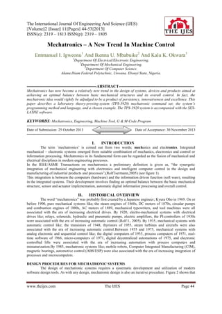
- 8. Mechatronics – A New Trend In… PROSPECTS OF MECHATRONICS In this age of human population boom, mechatronics has greatly proved to be the latest trend of modern engineering endeavors. Programmed files saved in the computer’s disk enables the engineer to manufacture the exact amount of products required, at the same level of accuracy. All it takes for mechatronic systems is to load the computer with the appropriate file and run the program. This process turns manufacturing activities significantly flexible hence; mechatronic machines are otherwise regarded as flexible manufacturing systems (FMS). IV. CONCLUSION Admittedly, despite the issues, problems and challenges in developing mechatronic systems, there are prospects of: sustainable design and pattern benefits for manufacturing industries and governments, which can be derived, beyond what has been reviewed by this paper. However, the key points to note are; 1. Flexibility in manufacturing, and optimum utilization of raw materials. 2. Unwavered automation with attendant advantages like: - High speed of operation - Increased quality control (less wastage) - Improved accuracy - Safety assurance and so on. Figure 1: Mechatronics- synergetic integration of different disciplines (Isremann, 2005) www.theijes.com The IJES Page 51
- 9. Mechatronics – A New Trend In… System Definition Traditional Engineering (Domain specification) Mechanical and electrical engineering Process Design Requirements & Engineering Specification Electronic Engineering Information And Control Engineering Info. Processing And Control Engineering Electronic Hardware Design Operating Engineering Human-machine interface design Integration of Components (hardware) Integration by information Processing (software) System integration (Hard- & Software) Integrated(simultaneous) engineering Integrated mechatronic system System Testing Manufacturing Engineering Mechatronic system Fig. 2: Design procedure for Mechtronic systems.( Isremannn, 2005) www.theijes.com The IJES Page 52
- 10. Mechatronics – A New Trend In… REFERENCES [1] [2] [3] [4] [5] [6] [7] Isremann, R. (2005): Mechatronic Systems Fundamentals. Spring-verlag London Ltd. Craig, J. (1989): Introduction to Robotics: Mechanics and Control, 2nd edn. Addison-wesley, Reading. AIM IEEE/ASME Conference on Advanced Intelligent Mechatronics. Atlanta (1999), Como (2001), Kobe(2003) Dorf, R.C., Bishop, R.H. (2000): Modern control systems, 9th edn. Prentice Hall, Englewood Cliff. Science and Technical Education Training Manual: CAD – CAM with SOLIDCAM for Turning. http://www.mechatronicconcept/turning.com Date accessed: 09/01/2013 http://www.mechatronics/edu.com Date accessed: 09/01/2013 www.theijes.com The IJES Page 53