SlideShare a Scribd company logo
1 of 5
Download to read offline
Fan Basics
Drive Arrangements for Centrifugal Fans†
SW - Single Width, SI - Single Inlet
DW - Double Width, DI - Double Inlet


Arr. 1 SWSI - For belt drive              Arr. 2 SWSI - For belt drive
or direct drive connection.               or direct drive connection.
Impeller over-hung. Two                   Impeller over-hung. Bearings
bearings on base.                         in bracket supported by fan
                                          housing.


Arr. 3 SWSI - For belt drive              Arr. 3 DWDI - For belt drive
or direct drive connection.               or direct connection. One
One bearing on each side                  bearing on each side and
supported by fan housing.                 supported by fan housing.


 †Adapted from AMCA Standard 99-2404-78
                                    9
Fan Basics
Drive Arrangements for Centrifugal Fans (cont.)
SW - Single Width, SI - Single Inlet
DW - Double Width, DI - Double Inlet


Arr. 4 SWSI - For direct             Arr. 7 SWSI - For belt drive
drive. Impeller over-hung on         or     direct  connection.
prime mover shaft. No bear-          Arrangement 3 plus base for
ings on fan. Prime mover             prime mover.
base mounted or integrally
directly connected.


Arr. 7 DWDI - For belt drive         Arr. 8 SWSI - For belt drive
or     direct  connection.           or     direct   connection.
Arrangement 3 plus base for          Arrangement      1      plus
prime mover.                         extended base for prime
                                     mover.


Arr. 9 SWSI - For belt drive.        Arr. 10 SWSI - For belt
Impeller   overhung,     two         drive. Impeller overhung,
bearings, with prime mover           two bearings, with prime
outside base.                        mover inside base.

                                10
Fan Basics
Rotation & Discharge Designations for
Centrifugal Fans*
Top Horizontal


      Clockwise                                   Counterclockwise
Top Angular Down


      Clockwise                                    Counterclockwise
Top Angular Up


     Clockwise                                    Counterclockwise
Down Blast


       Clockwise                                   Counterclockwise
* Rotation is always as viewed from drive side.

                                         11
Fan Basics
Rotation & Discharge Designations for
Centrifugal Fans* (cont.)
Up Blast


     Clockwise                                    Counterclockwise
Bottom Horizontal


       Clockwise                                  Counterclockwise

Bottom Angular Down


       Clockwise                                  Counterclockwise
Bottom Angular Up


        Clockwise                                 Counterclockwise

* Rotation is always as viewed from drive side.

                                       12
Fan Basics
Motor Positions for Belt Drive Centrifugal Fans†

To determine the location of the motor, face the drive side of the
fan and pick the proper motor position designated by the letters
W, X, Y or Z as shown in the drawing below.


†Adapted from AMCA Standard 99-2404-78

                                  13

More Related Content

What's hot

Libro hidraulica-d-160712-bombas
Libro hidraulica-d-160712-bombasLibro hidraulica-d-160712-bombas
Libro hidraulica-d-160712-bombasElias Flores
 
NETZSCH_Pumps_Comprehensive_ Solutions
NETZSCH_Pumps_Comprehensive_ SolutionsNETZSCH_Pumps_Comprehensive_ Solutions
NETZSCH_Pumps_Comprehensive_ SolutionsAndreas Schmidt
 
Venturi and orificemeter - Ed Ryan Ruales
Venturi and orificemeter - Ed Ryan RualesVenturi and orificemeter - Ed Ryan Ruales
Venturi and orificemeter - Ed Ryan RualesEd Ryan Ruales
 
Experimental evaluation of a francis turbine
Experimental evaluation of a francis turbineExperimental evaluation of a francis turbine
Experimental evaluation of a francis turbineeSAT Journals
 
Turbo machines basics slideshare
Turbo machines basics slideshareTurbo machines basics slideshare
Turbo machines basics slidesharePurushottam Ingle
 
PPT ON MINIMUM SPEED OF PUMP.pptx
PPT ON MINIMUM SPEED OF PUMP.pptxPPT ON MINIMUM SPEED OF PUMP.pptx
PPT ON MINIMUM SPEED OF PUMP.pptxKCNIT BANDA
 
VERTICAL PRESSURE VESSEL DESIGN 5.docx
VERTICAL PRESSURE VESSEL DESIGN 5.docxVERTICAL PRESSURE VESSEL DESIGN 5.docx
VERTICAL PRESSURE VESSEL DESIGN 5.docxTesemaTeshome
 
Instantaneous center method
Instantaneous center methodInstantaneous center method
Instantaneous center methodRohit Singla
 
FABRICATION OF PNEUMATIC CONTROLLED RAMMER STRIKER FOR MOULDING PROCES.pptx
FABRICATION  OF  PNEUMATIC CONTROLLED RAMMER STRIKER FOR MOULDING PROCES.pptxFABRICATION  OF  PNEUMATIC CONTROLLED RAMMER STRIKER FOR MOULDING PROCES.pptx
FABRICATION OF PNEUMATIC CONTROLLED RAMMER STRIKER FOR MOULDING PROCES.pptxchockalingam athilingam
 
Design of Axial Flow.pdf
Design of Axial Flow.pdfDesign of Axial Flow.pdf
Design of Axial Flow.pdfUZAIRMANSOOR4
 
Gears and gear trains may 2020
Gears and gear trains may 2020Gears and gear trains may 2020
Gears and gear trains may 2020Gaurav Mistry
 
Operation of reciprocating pump
Operation of reciprocating pumpOperation of reciprocating pump
Operation of reciprocating pumpvaibhav tailor
 

What's hot (20)

Libro hidraulica-d-160712-bombas
Libro hidraulica-d-160712-bombasLibro hidraulica-d-160712-bombas
Libro hidraulica-d-160712-bombas
 
NETZSCH_Pumps_Comprehensive_ Solutions
NETZSCH_Pumps_Comprehensive_ SolutionsNETZSCH_Pumps_Comprehensive_ Solutions
NETZSCH_Pumps_Comprehensive_ Solutions
 
Venturi and orificemeter - Ed Ryan Ruales
Venturi and orificemeter - Ed Ryan RualesVenturi and orificemeter - Ed Ryan Ruales
Venturi and orificemeter - Ed Ryan Ruales
 
Experimental evaluation of a francis turbine
Experimental evaluation of a francis turbineExperimental evaluation of a francis turbine
Experimental evaluation of a francis turbine
 
Turbo machines basics slideshare
Turbo machines basics slideshareTurbo machines basics slideshare
Turbo machines basics slideshare
 
Universal joints
Universal jointsUniversal joints
Universal joints
 
PPT ON MINIMUM SPEED OF PUMP.pptx
PPT ON MINIMUM SPEED OF PUMP.pptxPPT ON MINIMUM SPEED OF PUMP.pptx
PPT ON MINIMUM SPEED OF PUMP.pptx
 
VERTICAL PRESSURE VESSEL DESIGN 5.docx
VERTICAL PRESSURE VESSEL DESIGN 5.docxVERTICAL PRESSURE VESSEL DESIGN 5.docx
VERTICAL PRESSURE VESSEL DESIGN 5.docx
 
Instantaneous center method
Instantaneous center methodInstantaneous center method
Instantaneous center method
 
Venturimeter
VenturimeterVenturimeter
Venturimeter
 
Curved beams
Curved beamsCurved beams
Curved beams
 
FABRICATION OF PNEUMATIC CONTROLLED RAMMER STRIKER FOR MOULDING PROCES.pptx
FABRICATION  OF  PNEUMATIC CONTROLLED RAMMER STRIKER FOR MOULDING PROCES.pptxFABRICATION  OF  PNEUMATIC CONTROLLED RAMMER STRIKER FOR MOULDING PROCES.pptx
FABRICATION OF PNEUMATIC CONTROLLED RAMMER STRIKER FOR MOULDING PROCES.pptx
 
Design of Axial Flow.pdf
Design of Axial Flow.pdfDesign of Axial Flow.pdf
Design of Axial Flow.pdf
 
Fanno Flow
Fanno FlowFanno Flow
Fanno Flow
 
Gears and gear trains may 2020
Gears and gear trains may 2020Gears and gear trains may 2020
Gears and gear trains may 2020
 
Kaplan turbines
Kaplan turbinesKaplan turbines
Kaplan turbines
 
Refrigerant compressors
Refrigerant compressorsRefrigerant compressors
Refrigerant compressors
 
Mc conkey 13-pb
Mc conkey 13-pbMc conkey 13-pb
Mc conkey 13-pb
 
Operation of reciprocating pump
Operation of reciprocating pumpOperation of reciprocating pump
Operation of reciprocating pump
 
Riveted joints
Riveted jointsRiveted joints
Riveted joints
 

Fan orientation amca

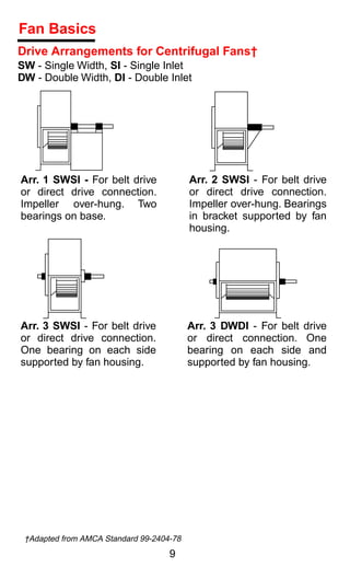
  • 1. Fan Basics Drive Arrangements for Centrifugal Fans† SW - Single Width, SI - Single Inlet DW - Double Width, DI - Double Inlet Arr. 1 SWSI - For belt drive Arr. 2 SWSI - For belt drive or direct drive connection. or direct drive connection. Impeller over-hung. Two Impeller over-hung. Bearings bearings on base. in bracket supported by fan housing. Arr. 3 SWSI - For belt drive Arr. 3 DWDI - For belt drive or direct drive connection. or direct connection. One One bearing on each side bearing on each side and supported by fan housing. supported by fan housing. †Adapted from AMCA Standard 99-2404-78 9
  • 2. Fan Basics Drive Arrangements for Centrifugal Fans (cont.) SW - Single Width, SI - Single Inlet DW - Double Width, DI - Double Inlet Arr. 4 SWSI - For direct Arr. 7 SWSI - For belt drive drive. Impeller over-hung on or direct connection. prime mover shaft. No bear- Arrangement 3 plus base for ings on fan. Prime mover prime mover. base mounted or integrally directly connected. Arr. 7 DWDI - For belt drive Arr. 8 SWSI - For belt drive or direct connection. or direct connection. Arrangement 3 plus base for Arrangement 1 plus prime mover. extended base for prime mover. Arr. 9 SWSI - For belt drive. Arr. 10 SWSI - For belt Impeller overhung, two drive. Impeller overhung, bearings, with prime mover two bearings, with prime outside base. mover inside base. 10
  • 3. Fan Basics Rotation & Discharge Designations for Centrifugal Fans* Top Horizontal Clockwise Counterclockwise Top Angular Down Clockwise Counterclockwise Top Angular Up Clockwise Counterclockwise Down Blast Clockwise Counterclockwise * Rotation is always as viewed from drive side. 11
  • 4. Fan Basics Rotation & Discharge Designations for Centrifugal Fans* (cont.) Up Blast Clockwise Counterclockwise Bottom Horizontal Clockwise Counterclockwise Bottom Angular Down Clockwise Counterclockwise Bottom Angular Up Clockwise Counterclockwise * Rotation is always as viewed from drive side. 12
  • 5. Fan Basics Motor Positions for Belt Drive Centrifugal Fans† To determine the location of the motor, face the drive side of the fan and pick the proper motor position designated by the letters W, X, Y or Z as shown in the drawing below. †Adapted from AMCA Standard 99-2404-78 13