SlideShare a Scribd company logo
1 of 86
Download to read offline
2009 Pontiac Solstice | SKY, Solstice (VIN M) Service Manual | Driveline/Axle | Propeller Shaft | Specifications |
Document ID: 1868126
Fastener Tightening Specifications
Application
Specification
Metric English
Driveline Support Bracket Bolts at Differential 80 N·m 59 lb ft
Driveline Support Bracket Bolts at Transmission 185 N·m 136 lb ft
Driveline Support at Differential 200 N·m 148 lb ft
Propeller Shaft C/V Flange Bolts - Front 40 N·m 30 lb ft
Rear Differential Mounting Bolt 175 N·m 129 lb ft
Rubber Couplings to Flanges - Rear 85 N·m 63 lb ft
© 2010 General Motors Corporation. All rights reserved.
Page 1 of 1Document ID: 1868126
2/22/2010http://localhost:9001/si/showDoc.do?docSyskey=1868126&pubCellSyskey=55239&pubO...
2009 Pontiac Solstice | SKY, Solstice (VIN M) Service Manual | Driveline/Axle | Propeller Shaft | Specifications |
Document ID: 1522874
Adhesives, Fluids, Lubricants, and Sealers
Application Type of Material
GM Part Number
United States Canada
Propeller Shaft Centering Bushings Lubricant 1051344 993037
Propeller Shaft-to-Flange Bolts Threadlocker 12345493 10953488
© 2010 General Motors Corporation. All rights reserved.
Page 1 of 1Document ID: 1522874
2/22/2010http://localhost:9001/si/showDoc.do?docSyskey=1522874&pubCellSyskey=64688&pubO...
2009 Pontiac Solstice | SKY, Solstice (VIN M) Service Manual | Driveline/Axle | Propeller Shaft | Repair Instructions |
Document ID: 2100740
Propeller Shaft, Differential, and Driveline Support
Replacement
Special Tools
J 44394 Axle Seal Protector
Removal Procedure
1. Remove the left rear wheel drive shaft. Refer to Wheel Drive Shaft Replacement.
2. Remove the muffler and exhaust pipe. Refer to Exhaust Muffler Replacement.
3. Remove the floor panel tunnel panel front closeout panel. Refer to Floor Panel Tunnel Panel
Replacement - Front.
4. Remove the floor panel tunnel rear panel. Refer to Floor Panel Tunnel Panel Replacement -
Rear.
5. Support the transmission with a suitable jack stand.
6. Loosen, but DO NOT remove the driveline support to the transmission bolts (1).
7. Remove the transmission close out panel. Refer to Transmission Support Replacement.
8. Loosen, but DO NOT remove the left and right motor mount bolts.
• For vehicles equipped with the 2.0L, refer to Engine Mount Replacement - Left Side and
Engine Mount Replacement - Right Side.
• For vehicles equipped with the 2.4L, refer to Engine Mount Replacement - Left Side and
Engine Mount Replacement - Right Side.
© 2010 General Motors Corporation. All rights reserved.
Page 1 of 14Document ID: 2100740
2/22/2010http://localhost:9001/si/showDoc.do?docSyskey=2100740&pubCellSyskey=163575&pub...
9. Remove the front propeller shaft bolts (1) and washer support tabs (2) from the
transmission.
10. Support the rear differential with a transmission jack stand.
Page 2 of 14Document ID: 2100740
2/22/2010http://localhost:9001/si/showDoc.do?docSyskey=2100740&pubCellSyskey=163575&pub...
Note: The proper nuts and bolts to be removed are those where the nut is the closest or
facing the rear differential drive flange. DO NOT remove the nuts and bolt where the nuts are
facing the front or propeller shaft.
11. Remove the propeller shaft nuts and bolts from the rear differential.
12. Remove the left (1) and right (2) rear differential mount bolts.
13. Lower the rear differential enough to clear the rear crossmember.
14. Install the J 44394 protector and move the rear differential to the left side of the vehicle to
remove the right rear wheel drive shaft.
Page 3 of 14Document ID: 2100740
2/22/2010http://localhost:9001/si/showDoc.do?docSyskey=2100740&pubCellSyskey=163575&pub...
Note: DO NOT re-use the bolts, discard and use NEW only.
15. Remove the four differential carrier bracket bolts (1).
16. Separate the differential carrier (1) from the driveline support bracket (2).
Page 4 of 14Document ID: 2100740
2/22/2010http://localhost:9001/si/showDoc.do?docSyskey=2100740&pubCellSyskey=163575&pub...
17. Remove the propeller shaft from the vehicle.
Note: Steps 18 and 19 are for the replacing the driveline support.
18. Remove the driveline support bolts (1) and the washers (2) from the transmission.
Page 5 of 14Document ID: 2100740
2/22/2010http://localhost:9001/si/showDoc.do?docSyskey=2100740&pubCellSyskey=163575&pub...
19. Remove the driveline support (1) from the transmission and the rear differential assembly.
20. If servicing the driveline support, remove the nut (1), bolt (2), and the washer block (3) from
the driveline support.
21. Remove the driveline support (4) from the rear differential assembly.
Page 6 of 14Document ID: 2100740
2/22/2010http://localhost:9001/si/showDoc.do?docSyskey=2100740&pubCellSyskey=163575&pub...
Note: Support the right rear wheel drive shaft with mechanics wire.
22. If servicing the rear differential assembly, remove the rear differential assembly from the
vehicle.
Installation Procedure
1. Clean the bolt holes in the differential carrier with brake cleaner or other suitable solvents to
remove any adhesive.
2. If servicing the driveline support, position the driveline support (4) on the differential
housing.
3. Install the bolt plate (3), bolts (2) for the driveline support on the differential housing.
Page 7 of 14Document ID: 2100740
2/22/2010http://localhost:9001/si/showDoc.do?docSyskey=2100740&pubCellSyskey=163575&pub...
Caution: Refer to Component Fastener Tightening Caution in the Preface section.
4. Install the nuts (1) for the drive line support bolts (2) and tighten to 200 N·m (148 lb ft).
5. Position the driveline support (1) on the transmission.
Note: Leave the driveline support bolts loose.
6. Install the driveline support bolts (1) and washers (2).
Page 8 of 14Document ID: 2100740
2/22/2010http://localhost:9001/si/showDoc.do?docSyskey=2100740&pubCellSyskey=163575&pub...
7. Raise the differential to just below the rear crossmember.
8. Clean the pilot shaft (1) and the pilot hole (2) of any dirt or debris.
9. Apply a small amount of chassis lube on the pilot shaft (1).
10. Align the pilot shaft (1) and the pilot hole (2).
Page 9 of 14Document ID: 2100740
2/22/2010http://localhost:9001/si/showDoc.do?docSyskey=2100740&pubCellSyskey=163575&pub...
11. Install the propeller shaft to the transmission and differential.
Note: In steps 11 and 12, finger tighten the front and rear propeller shaft nuts and bolts
only. DO NOT torque the propeller shaft nuts and bolts until the differential and driveline
support have been aligned and torqued to specifications.
12. Install the propeller shaft bolts (1) and washer support tabs (2) in the transmission drive
flange.
Page 10 of 14Document ID: 2100740
2/22/2010http://localhost:9001/si/showDoc.do?docSyskey=2100740&pubCellSyskey=163575&pub...
Note: Ensure that the driveline support bracket and the differential are properly joined.
13. Align the differential carrier (1) and the torque beam bracket (2).
14. Apply GM threadlocker to the NEW differential carrier bracket bolts (1). Refer to Adhesives,
Fluids, Lubricants, and Sealers.
Note: Use only hands tools to tighten the driveline support bolts.
15. Install the four new driveline support bracket bolts (1) and tighten to 80 N·m (59 lb ft).
16. Raise and position the differential in the rear support.
Page 11 of 14Document ID: 2100740
2/22/2010http://localhost:9001/si/showDoc.do?docSyskey=2100740&pubCellSyskey=163575&pub...
Note: Install the left and right rear differential bolts by hand before tightening to
specifications.
17. Install the left (1) and right (2) rear differential bolt and tighten to 175 N·m (129 lb ft).
18. Tighten the rear propeller shaft bolts to 85 N·m (63 lb ft).
19. Tighten the front propeller shaft bolts in sequence (1-6) to 40 N·m (30 lb ft).
20. Install the left rear wheel drive shaft. Refer to Wheel Drive Shaft Replacement.
Page 12 of 14Document ID: 2100740
2/22/2010http://localhost:9001/si/showDoc.do?docSyskey=2100740&pubCellSyskey=163575&pub...
Note: Failing to perform the following service procedure will create the wrong driveline angle
for the propeller shaft and alignment of the transmission and the rear differential.
21. Position a scale or known straight edge across the floor pan where the driveline tunnel
closeout mounts to the body.
22. Position another scale at the transmission output shaft oil seal slinger.
23. Using the jack stand, raise or lower the transmission until a measurement of 80 mm
(3.150 inch) is obtained.
24. Tighten the driveline support bolts (1) at the transmission to 185 N·m (136 lb ft).
25. Remove the jack stand from the rear differential.
26. Tighten the left and right motor mount bolts.
• For vehicles equipped with the 2.0L, refer to Engine Mount Replacement - Left Side and
Page 13 of 14Document ID: 2100740
2/22/2010http://localhost:9001/si/showDoc.do?docSyskey=2100740&pubCellSyskey=163575&pub...
27. Remove the transmission jack stand.
28. Install the transmission close out panel. Refer to Transmission Support Replacement.
29. Install the floor panel tunnel panel front closeout panel. Refer to Floor Panel Tunnel Panel
Replacement - Front.
30. Install the floor panel tunnel rear panel. Refer to Floor Panel Tunnel Panel Replacement -
Rear.
31. Install the muffler and exhaust pipe from the vehicle. Refer to Exhaust Muffler Replacement.
Engine Mount Replacement - Right Side.
• For vehicles equipped with the 2.4L, refer to Engine Mount Replacement - Left Side and
Engine Mount Replacement - Right Side.
Page 14 of 14Document ID: 2100740
2/22/2010http://localhost:9001/si/showDoc.do?docSyskey=2100740&pubCellSyskey=163575&pub...
2009 Pontiac Solstice | SKY, Solstice (VIN M) Service Manual | Driveline/Axle | Propeller Shaft | Repair Instructions |
Document ID: 2101015
Propeller Shaft Replacement (Automatic)
Removal Procedure
1. Raise and support the vehicle. Refer to Lifting and Jacking the Vehicle.
2. Remove the exhaust pipe and muffler. Refer to Muffler Replacement.
3. Remove the floor panel rear panel. Refer to Floor Panel Tunnel Panel Replacement - Rear.
4. Support the rear differential assembly with a suitable jack stand.
5. Remove the left (1) and right (2) rear differential support bolts.
6. Remove the front differential support bolt (1).
© 2010 General Motors Corporation. All rights reserved.
Page 1 of 5Document ID: 2101015
2/22/2010http://localhost:9001/si/showDoc.do?docSyskey=2101015&pubCellSyskey=55284&pubO...
7. Remove the propeller shaft bolts from the transmission output flange.
8. Remove the propeller shaft nut and bolts from the differential drive flange.
9. Lower the rear differential assembly enough to remove the propeller shaft from the vehicle.
Installation Procedure
1. Remove all debris from the pilot shaft.
2. Apply a small amount of chassis lube on the pilot shaft and pilot shaft hole in the propeller
shaft.
3. Position the propeller shaft on the transmission output flange.
4. Raise the rear differential at the same time as aligning the propeller shaft pilot shaft and the
propeller shaft pilot hole.
Page 2 of 5Document ID: 2101015
2/22/2010http://localhost:9001/si/showDoc.do?docSyskey=2101015&pubCellSyskey=55284&pubO...
Note: DO NOT tighten the propeller shaft front or rear fasteners until the front and rear
differential support bolts are tighten to specifications.
5. Hand tighten the propeller shaft bolts to the transmission output shaft flange.
6. Hand tighten the nuts and bolts to the rear differential drive flange.
7. Position the rear differential assembly in the support.
Caution: Refer to Fastener Caution in the Preface section.
Page 3 of 5Document ID: 2101015
2/22/2010http://localhost:9001/si/showDoc.do?docSyskey=2101015&pubCellSyskey=55284&pubO...
8. Install the left (1) and right (2) rear differential support bolts and tighten to 175 N·m
(129 lb ft).
9. Install the front differential support bolt (1) and tighten to 175 N·m (129 lb ft).
10. Remove the jack stand from the rear differential assembly.
Page 4 of 5Document ID: 2101015
2/22/2010http://localhost:9001/si/showDoc.do?docSyskey=2101015&pubCellSyskey=55284&pubO...
11. Tighten the front propeller shaft bolts in sequence 1-6 to 40 N·m (30 lb ft).
12. Tighten the rear propeller shaft bolts and tighten to 85 N·m (63 lb ft).
13. Install the floor panel rear panel. Refer to Floor Panel Tunnel Panel Replacement - Rear.
14. Install the exhaust pipe and muffler. Refer to Muffler Replacement.
15. Remove the support and lower the vehicle.
Page 5 of 5Document ID: 2101015
2/22/2010http://localhost:9001/si/showDoc.do?docSyskey=2101015&pubCellSyskey=55284&pubO...
2009 Pontiac Solstice | SKY, Solstice (VIN M) Service Manual | Driveline/Axle | Propeller Shaft | Repair Instructions |
Document ID: 2157340
Propeller Shaft Replacement (RPO ZOK)
Callout Component Name
Preliminary Procedures
1. Remove the floor panel tunnel rear panel. Refer to Floor Panel Tunnel Panel
Replacement - Rear.
2. Support the rear drive module (RDM).
3. Remove the bolt from the differential case bracket assembly to body.
1
Propeller Shaft Coupling Nut (Qty: 3)
Caution: Refer to Fastener Caution in the Preface section.
Tip
Tighten
85 N·m (63 lb ft)
• DO NOT remove the bolts from the coupler to the propeller shaft. Remove
only the bolts from the coupler to the drive axle pinion flange.
• Clean the threads and apply LOCTITE. Refer to Adhesives, Fluids, Lubricants,
and Sealers.
2 Propeller Shaft Coupler Bolt (Qty: 3)
© 2010 General Motors Corporation. All rights reserved.
Page 1 of 2Document ID: 2157340
2/22/2010http://localhost:9001/si/showDoc.do?docSyskey=2157340&pubCellSyskey=55284&pubO...
3
CV Joint Mounting Bolt (Qty: 6)
Tip
Tighten
40 N·m (30 lb ft)
• The CV joint mounting bolts MUST be tightened in a star pattern sequence.
• Clean the threads and apply LOCTITE. Refer to Adhesives, Fluids, Lubricants,
and Sealers.
4 CV Joint Mounting Bolt Spacer
5
Propeller Shaft
Tip
• Before installation, apply a small amount of lubricant to the front and rear
propeller shaft center bushings. Refer to Adhesives, Fluids, Lubricants, and
Sealers.
• Lower the front of the RDM to remove the propeller shaft from the pinion
flange.
Page 2 of 2Document ID: 2157340
2/22/2010http://localhost:9001/si/showDoc.do?docSyskey=2157340&pubCellSyskey=55284&pubO...
2009 Pontiac Solstice | SKY, Solstice (VIN M) Service Manual | Driveline/Axle | Rear Drive Axle | Specifications |
Document ID: 1868149
Fastener Tightening Specifications
Application
Specification
Metric English
Differential Carrier Bracket to Bracket Reinforcement Bolt
(Automatic only)
175 N·m 129 lb ft
Differential Carrier Bracket Reinforcement (Automatic only) 110 N·m + 20 degrees --
Driveline Support to Driveline Support Bracket Bolts
(Manual Only)
200 N·m 148 lb ft
Driveline Support Bracket to Differential Bolts 80 N·m 59 lb ft
Differential Carrier Cover Bolts 25 N·m 18 lb ft
Differential Ring Gear Bolts 185 N·m 136 lb ft
Differential Drain Plug 35 N·m 26 lb ft
Differential Drive Pinion Flange Nut 245 N·m 181 lb ft
Differential Fill Plug 35 N·m 26 lb ft
Differential Rear Mounting Bolts 175 N·m 129 lb ft
Propeller Shaft Coupler-to-Differential Flange Bolts 85 N·m 63 lb ft
Propeller Shaft to Transmission Output Shaft Bolts 40 N·m 30 lb ft
© 2010 General Motors Corporation. All rights reserved.
Page 1 of 1Document ID: 1868149
2/22/2010http://localhost:9001/si/showDoc.do?docSyskey=1868149&pubCellSyskey=55636&pubO...
2009 Pontiac Solstice | SKY, Solstice (VIN M) Service Manual | Driveline/Axle | Rear Drive Axle | Specifications |
Document ID: 1702638
Lubrication Specifications
Capacities
Application
Quantity
Metric English
Synthetic Differential Lubricant GL-5 75W90 G/M P/N 89021677 (Canadian P/N 89021678)
l Drain and Fill, if differential side cover has been removed to service any internal
differential component.
For vehicles equipped the Limited Slip Differential 1.2 L 1.26 Qt
For vehicles not equipped with the Limited Slip Differential 1.3 L 1.3 Qt
l Drain and Fill with use of drain plug. 1.1 L 1.16 Qt
Important: The following is for vehicles equipped with the Limited Slip Differential option.
The Limited Slip Additive container capacity is greater than the amount needed. Only add
the amount specified.
Limited Slip Differential Lubricant Additive GM P/N 1052358 (Canadian P/N 992694)
l Drain and Fill with cover removed. 100 ml 3.38 oz
l Drain and Fill with use of drain plug. 70 ml 2.37 oz
© 2010 General Motors Corporation. All rights reserved.
Page 1 of 1Document ID: 1702638
2/22/2010http://localhost:9001/si/showDoc.do?docSyskey=1702638&pubCellSyskey=55652&pubO...
2009 Pontiac Solstice | SKY, Solstice (VIN M) Service Manual | Driveline/Axle | Rear Drive Axle | Specifications |
Document ID: 1768573
Rear Axle Specifications
Application
Specification
Metric English
Differential Case Shim Sizes 3.5-4.4 mm 0.14-0.17 in
Pinion Housing Shim Sizes 1.2-1.9 mm 0.04-0.07 in
Pinion Rotating Torque w/Seals 2.5-4 N·m 22-35 lb in
Ring Gear/Pinion A1 Nominal Value - All Axles 111.00 mm 4.37 in
Ring Gear/Pinion A2 Nominal Value - 3.91 Ratio Axle 63.5 mm 2.50 in
Torsional Backlash
l 3.91 Ratio Axle with 105 mm Flange 0.25-0.41 mm 0.010-0.016 in
© 2010 General Motors Corporation. All rights reserved.
Page 1 of 1Document ID: 1768573
2/22/2010http://localhost:9001/si/showDoc.do?docSyskey=1768573&pubCellSyskey=55767&pubO...
2009 Pontiac Solstice | SKY, Solstice (VIN M) Service Manual | Driveline/Axle | Rear Drive Axle | Specifications |
Document ID: 1768587
Rear Axle Usage
(1) Ratio
(2) GM Part Number
(3) Getrag Part Number
(4) Serial Number
Available Axle Ratios
Axle Ratio Drive/Engine Flange Size
3:91 RWD/2.4L L4 105 mm
© 2010 General Motors Corporation. All rights reserved.
Page 1 of 1Document ID: 1768587
2/22/2010http://localhost:9001/si/showDoc.do?docSyskey=1768587&pubCellSyskey=55786&pubO...
2009 Pontiac Solstice | SKY, Solstice (VIN M) Service Manual | Driveline/Axle | Rear Drive Axle | Specifications |
Document ID: 784775
Adhesives, Fluids, Lubricants, and Sealers
Application Type of Material
GM Part Number
US Canada
Rear Differential Lubricant Axle Lubricant (Synthetic) 12378261 10953455
Pinion Nut Thread Locker 12345382 10953489
© 2010 General Motors Corporation. All rights reserved.
Page 1 of 1Document ID: 784775
2/22/2010http://localhost:9001/si/showDoc.do?docSyskey=784775&pubCellSyskey=55680&pubObj...
2009 Pontiac Solstice | SKY, Solstice (VIN M) Service Manual | Driveline/Axle | Rear Drive Axle | Visual Identification |
Document ID: 2001093
Rear Axle Identification
(1) Axle Ratio
(2) GM Part Number
(3) Bar Code
(4) Getrag Logo
(5) Getrag Part Number
(6) Getrag Serial Number
(7) GM Logo
© 2010 General Motors Corporation. All rights reserved.
Page 1 of 1Document ID: 2001093
2/22/2010http://localhost:9001/si/showDoc.do?docSyskey=2001093&pubCellSyskey=55666&pubO...
2009 Pontiac Solstice | SKY, Solstice (VIN M) Service Manual | Driveline/Axle | Rear Drive Axle | Component Locator |
Document ID: 1387527
Limited Slip Differential Disassembled Views
Differential Components
(101) Bearing
(101) Bearing
(102) Bolt
(103) Differential Shaft
(104) Left Case Half
(105) Right Case Half
(106) Ring Gear
(107) Axle Side Gear
(108) Beveled Washer
(109) Plate/Separator
(110) Clutch Pack
(110) Clutch Pack
(111) Pinion Gear
(111) Pinion Gear
(112) Washer © 2010 General Motors Corporation. All rights reserved.
Page 1 of 2Document ID: 1387527
2/22/2010http://localhost:9001/si/showDoc.do?docSyskey=1387527&pubCellSyskey=150340&pub...
(112) Washer
Page 2 of 2Document ID: 1387527
2/22/2010http://localhost:9001/si/showDoc.do?docSyskey=1387527&pubCellSyskey=150340&pub...
2009 Pontiac Solstice | SKY, Solstice (VIN M) Service Manual | Driveline/Axle | Rear Drive Axle | Component Locator |
Document ID: 1792398
Rear Axle Disassembled Views
(1) Differential Carrier
(2) Carrier Cover
(3) Pinion Bearing Gage
(4) Nut
(5) Flange
(6) Pinion Oil Seal
(7) Bearing
(8) Cup
(9) Bolt
(10) Shim
(11) O-ring Seal
(12) Pinion Bearing Spacer
(13) Cup
(14) Bearing
(15) Bolt
(16) Differential Carrier Bracket
(17) Axle Oil Seal
(17) Axle Oil Seal
© 2010 General Motors Corporation. All rights reserved.
Page 1 of 2Document ID: 1792398
2/22/2010http://localhost:9001/si/showDoc.do?docSyskey=1792398&pubCellSyskey=55801&pubO...
(18) Drain Plug
(19) Shim
(19) Shim
(20) Cup
(20) Cup
(21) O-ring Seal
(22) Vent
(23) Fill Plug
(24) Bolt
(25) Fill Plug Washer
(100) Differential Assembly
(110) Pinion Gear
Page 2 of 2Document ID: 1792398
2/22/2010http://localhost:9001/si/showDoc.do?docSyskey=1792398&pubCellSyskey=55801&pubO...
2009 Pontiac Solstice | SKY, Solstice (VIN M) Service Manual | Driveline/Axle | Rear Drive Axle | Repair Instructions |
Document ID: 2101300
Rear Axle Lubricant Level Inspection
1. Raise and support the vehicle. Refer to Lifting and Jacking the Vehicle.
2. Clean any dirt from around the differential fill plug.
3. Remove the fill plug from the differential and drain the fluid.
4. Check the differential fluid level. It should be even with the bottom of the fill plug hole to no
lower than 6 mm (0.25 in) below the opening.
5. Add new fluid if necessary.
6. Fill the differential with 75W90 synthetic axle lubricant. Refer to Approximate Fluid Capacities
and Lubrication Specifications.
Caution: Refer to Fastener Caution in the Preface section.
7. Install the differential fill plug to the differential and tighten to 35 N·m (26 lb ft).
8. Lower the vehicle.
© 2010 General Motors Corporation. All rights reserved.
Page 1 of 1Document ID: 2101300
2/22/2010http://localhost:9001/si/showDoc.do?docSyskey=2101300&pubCellSyskey=69628&pubO...
2009 Pontiac Solstice | SKY, Solstice (VIN M) Service Manual | Driveline/Axle | Rear Drive Axle | Repair Instructions |
Document ID: 2101301
Axle Lubricant Change
Draining Procedure
1. Raise and support the vehicle. Refer to Lifting and Jacking the Vehicle.
2. Clean any dirt from around the differential drain plug.
3. Position a drain pan under drain plug.
4. Remove the drain plug from the differential and drain the fluid.
Filling Procedure
Caution: Refer to Fastener Caution in the Preface section.
© 2010 General Motors Corporation. All rights reserved.
Page 1 of 3Document ID: 2101301
2/22/2010http://localhost:9001/si/showDoc.do?docSyskey=2101301&pubCellSyskey=55648&pubO...
1. Install the drain plug to the differential and tighten to 35 N·m (26 lb ft)..
2. Clean any dirt from around the differential fill plug.
3. Remove the fill plug from the differential.
Note: If equipped with a limited slip differential, limited slip differential lubricant additive,
GM P/N 1052358 (Canadian P/N 992694) or equivalent must be added first. Refer to
Lubrication Specifications . Approximately 0.23 L (7.8 oz) of residual fluid will remain in the
differential.
4. Fill the differential with 75W90 synthetic axle lubricant, GM P/N 12378261
(Canadian P/N 10953455) or equivalent. Refer to Lubrication Specifications.
5. Inspect the gear lubricant level to ensure it is even with the bottom of the fill plug hole to no
lower than 6 mm (0.25 in) below the opening.
Page 2 of 3Document ID: 2101301
2/22/2010http://localhost:9001/si/showDoc.do?docSyskey=2101301&pubCellSyskey=55648&pubO...
6. Install the fill plug to the differential and tighten to 35 N·m (26 lb ft).
7. Lower the vehicle.
Page 3 of 3Document ID: 2101301
2/22/2010http://localhost:9001/si/showDoc.do?docSyskey=2101301&pubCellSyskey=55648&pubO...
2009 Pontiac Solstice | SKY, Solstice (VIN M) Service Manual | Driveline/Axle | Rear Drive Axle | Repair Instructions |
Document ID: 2101303
Differential Carrier Cover and Seal Replacement - Left
Side
Removal Procedure
1. Remove the rear differential. Refer to Differential Replacement.
2. Remove the 9 carrier cover bolts (6).
3. Using the pry tabs (4, 5, 7), remove the carrier cover (3) from the differential carrier (1).
4. Remove the O-ring seal (2) from the cover (3).
Installation Procedure
© 2010 General Motors Corporation. All rights reserved.
Page 1 of 2Document ID: 2101303
2/22/2010http://localhost:9001/si/showDoc.do?docSyskey=2101303&pubCellSyskey=55822&pubO...
1. Install the housing cover O-ring (2) into the groove on the housing cover (3).
2. Apply a light coat of oil to the housing cover O-ring (2) and install the housing cover (3) onto
the housing (1).
Caution: Refer to Fastener Caution in the Preface section.
3. Install the 9 side cover bolts (4) and tighten in a criss-cross pattern to 29 N·m (21 lb ft).
4. Install the rear differential. Refer to Differential Replacement.
Page 2 of 2Document ID: 2101303
2/22/2010http://localhost:9001/si/showDoc.do?docSyskey=2101303&pubCellSyskey=55822&pubO...
2009 Pontiac Solstice | SKY, Solstice (VIN M) Service Manual | Driveline/Axle | Rear Drive Axle | Repair Instructions |
Document ID: 1583106
Output Shaft Seal Replacement
Tools Required
J 45017 Output Shaft Seal Installer
Removal Procedure
1. Raise and suitably support the vehicle. Refer to Lifting and Jacking the Vehicle .
2. Remove the appropriate rear tire and wheel assembly. Refer to Tire and Wheel Removal and
Installation .
3. Remove the appropriate wheel drive shaft. Refer to Wheel Drive Shaft Replacement .
4. Using a flat bladed tool remove the differential output shaft seal.
Take care not to damage any sealing surfaces.
Installation Procedure
1. Lubricate the wheel drive shaft sealing surface of the oil seal with 75W90 synthetic axle
lubricant, GM P/N 12378261 (Canadian P/N 10953455) or equivalent.
2. Install the differential output shaft seal (2) to the J 45017 .
3. Using the J 45017 (1), install the differential output shaft seal (2).
4. Remove J 45017 (1) from the differential output shaft seal (2).
5. Install the wheel drive shaft. Refer to Wheel Drive Shaft Replacement .
6. Inspect the fluid level. Refer to Rear Axle Lubricant Level Inspection .
7. Install the rear tire and wheel assembly. Refer to Tire and Wheel Removal and Installation .
8. Lower the vehicle.
© 2010 General Motors Corporation. All rights reserved.
Page 1 of 1Document ID: 1583106
2/22/2010http://localhost:9001/si/showDoc.do?docSyskey=1583106&pubCellSyskey=55800&pubO...
2009 Pontiac Solstice | SKY, Solstice (VIN M) Service Manual | Driveline/Axle | Rear Drive Axle | Repair Instructions |
Document ID: 2157343
Drive Pinion Flange/Yoke and/or Oil Seal Replacement
Special Tools
Removal Procedure
1. Raise and support the vehicle. Refer to Lifting and Jacking the Vehicle.
2. Remove the floor panel tunnel rear panel. Refer to Floor Panel Tunnel Panel Replacement -
Rear.
Note: The following service procedure is for those vehicles equipped with a manual
transmission and drive line support. For vehicles equipped with a automatic transmission,
proceed to step 4.
3. Remove the propeller shaft, differential and driveline support. Refer to Propeller Shaft,
Differential, and Driveline Support Replacement.
Note: Remove only the propeller shaft coupler to differential flange bolts. DO NOT remove
the coupler from the propeller shaft.
4. Remove the propeller shaft from the rear differential. Refer to Propeller Shaft Replacement.
5. Carefully position the propeller shaft to the side and support using a suitable jack stand.
6. Remove the differential carrier bracket. Refer to Differential Carrier Bracket Replacement
• J 34826 Hub Nut Socket (36 mm)
• J 42851 Front Cover Oil Seal Installer
• J 45012 Holding Fixture
• J 45019 Flange and Pinion Cage Remover
© 2010 General Motors Corporation. All rights reserved.
Page 1 of 4Document ID: 2157343
2/22/2010http://localhost:9001/si/showDoc.do?docSyskey=2157343&pubCellSyskey=55807&pubO...
7. Install the J 45012 to the flange.
8. While holding the J 45012 , remove the drive pinion nut using the J 34826 .
9. Remove the J 45012 from the flange.
10. Install the J 45019 to the flange.
11. Using the J 45019 , remove the flange.
12. Using a flat-bladed tool, remove the drive pinion seal. care not to damage any of the sealing
surfaces.
Installation Procedure
Note: Ensure that the pinion bore is free of dirt and debris.
1. Apply a small amount of synthetic gear oil GM P/N 121378514 (Canadian P/N 88901045) or
equivalent to the surface of the drive pinion flange and the drive pinion seal.
Page 2 of 4Document ID: 2157343
2/22/2010http://localhost:9001/si/showDoc.do?docSyskey=2157343&pubCellSyskey=55807&pubO...
2. Install the drive pinion seal to the J 42851 .
3. Using the J 42851 (1) , install the drive pinion seal (2) in the differential (3).
4. Remove the J 45019 (1).
5. Install the J 45012 .
6. Install the pinion flange to the drive pinion shaft.
Note: The pinion shaft threads and pinion flange nut must be free of residue and debris prior
to application of the threadlocker.
7. Clean all the residue from the pinion shaft threads and the pinion flange nut by using
denatured alcohol or equivalent and allow to dry.
Note: Ensure that there are no gaps in the threadlocker along the length of the filled area of
the pinion shaft threads.
8. Apply the threadlocker GM P/N 12345382 (Canadian P/N 10953489) or equivalent to 2/3 of
the threads length of the pinion shaft threads.
9. Allow the threadlocker to cure approximately 10 minutes before installation.
Caution: Refer to Fastener Caution in the Preface section.
10. Install the drive pinion flange nut to the pinion shaft. While holding the J 45012 , use the J
34826 to tighten the drive pinion nut.
Tighten
Tighten the pinion flange nut to 245 N·m (181 lb ft).
11. Remove the J 45012 .
12. Install the differential carrier bracket. Refer to Differential Carrier Bracket Replacement
Page 3 of 4Document ID: 2157343
2/22/2010http://localhost:9001/si/showDoc.do?docSyskey=2157343&pubCellSyskey=55807&pubO...
Note: The following service procedure is for those vehicles equipped with a manual
transmission and drive line support. For vehicles equipped with a automatic transmission,
proceed to step 15.
13. Install the propeller shaft, differential and driveline support. Refer to Propeller Shaft,
Differential, and Driveline Support Replacement.
14. Install the propeller shaft to the differential. Refer to Propeller Shaft Replacement.
15. Install the floor panel tunnel rear panel. Refer to Floor Panel Tunnel Panel Replacement -
Rear.
16. Inspect the fluid level Refer to Rear Axle Lubricant Level Inspection.
17. Remove the support and lower the vehicle.
Page 4 of 4Document ID: 2157343
2/22/2010http://localhost:9001/si/showDoc.do?docSyskey=2157343&pubCellSyskey=55807&pubO...
2009 Pontiac Solstice | SKY, Solstice (VIN M) Service Manual | Driveline/Axle | Rear Drive Axle | Repair Instructions |
Document ID: 2151286
Differential Carrier Bracket Replacement
Removal Procedure
Note: Some portions of the frame and under body have been removed for the clarity of the
location of the differential carrier bracket.
1. Raise and support the vehicle. Refer to Lifting and Jacking the Vehicle.
2. Remove the floor panel tunnel rear panel. Refer to Floor Panel Tunnel Panel Replacement -
Rear.
3. Support the rear differential carrier assembly with a suitable jack stand.
© 2010 General Motors Corporation. All rights reserved.
Page 1 of 4Document ID: 2151286
2/22/2010http://localhost:9001/si/showDoc.do?docSyskey=2151286&pubCellSyskey=143204&pub...
4. Remove the differential mounting bracket bolt (1) frame bracket.
Note: The following service procedure is to allow for enough clearance to remove the
differential mounting bracket.
5. Loosen the 2 frame bracket bolts (2).
Note: DO NOT re-use the differential carrier bracket bolts. Discard and use NEW only.
6. Remove the 4 differential carrier mounting bracket bolts (1).
7. Remove the differential carrier mounting bracket (2).
Installation Procedure
1. Remove any thread locker from the bolt holes in the differential carrier with brake clean or
equivalent.
Page 2 of 4Document ID: 2151286
2/22/2010http://localhost:9001/si/showDoc.do?docSyskey=2151286&pubCellSyskey=143204&pub...
2. Position the differential carrier bracket (2) on the differential.
3. Apply GM threadlocker P/N 89021297 (Canadian P/N 10953488) or equivalent to the NEW
differential carrier bracket bolts (1).
Caution: Refer to Fastener Caution in the Preface section.
4. Install the 4 NEW differential carrier bracket bolts (1) and tighten to 80 N·m (59 lb ft).
5. Hand tighten the differential frame bracket to differential carrier bolt (1).
6. Install the 2 differential carrier bracket to frame bolts (2) and tighten to 110 N·m (81 lb ft)
plus 20 degrees.
7. Tighten the differential carrier bracket bolt (1) to 175 N·m (122 lb ft).
Page 3 of 4Document ID: 2151286
2/22/2010http://localhost:9001/si/showDoc.do?docSyskey=2151286&pubCellSyskey=143204&pub...
8. Remove the jack stand.
9. Install the floor panel tunnel rear panel. Refer to Floor Panel Tunnel Panel Replacement -
Rear.
10. Remove the support and lower the vehicle.
Page 4 of 4Document ID: 2151286
2/22/2010http://localhost:9001/si/showDoc.do?docSyskey=2151286&pubCellSyskey=143204&pub...
2009 Pontiac Solstice | SKY, Solstice (VIN M) Service Manual | Driveline/Axle | Rear Drive Axle | Repair Instructions |
Document ID: 2101310
Differential Replacement
Removal Procedure
1. Raise and support the vehicle. Refer to Lifting and Jacking the Vehicle.
2. Remove propeller shaft. Refer to Propeller Shaft Replacement.
3. Remove the rear tire and wheel assemblies. Refer to Tire and Wheel Removal and
Installation.
4. Remove the right and left wheel drive shafts. Refer to Wheel Drive Shaft Replacement.
5. Position a transmission jack beneath the differential.
6. Firmly secure the differential to the transmission jack.
© 2010 General Motors Corporation. All rights reserved.
Page 1 of 4Document ID: 2101310
2/22/2010http://localhost:9001/si/showDoc.do?docSyskey=2101310&pubCellSyskey=55773&pubO...
7. Remove the front differential carrier bracket-to-frame bolt (1).
8. Remove the left (1) and right (2) differential rear mounting bolts.
9. Lower the jack slightly until the mounting ear at the front of the differential clears the
support attachment point.
10. Remove the differential from the vehicle.
Installation Procedure
Note: The differential is shipped with a plastic vent plug. Remove the plastic vent plug prior
to differential vent installation.
1. When replacing the differential. remove the plastic vent plug and install a new differential
vent.
The vent flange must be fully seated.
2. With the differential firmly attached to the jack, raise the differential to the vehicle.
Page 2 of 4Document ID: 2101310
2/22/2010http://localhost:9001/si/showDoc.do?docSyskey=2101310&pubCellSyskey=55773&pubO...
3. Hand install the differential carrier bracket-to-frame bolt (1) in order to locate the differential
to the rear support.
4. With the differential firmly attached to the jack, raise the differential to the rear support.
5. Position the differential to the support.
Caution: Refer to Fastener Caution in the Preface section.
Page 3 of 4Document ID: 2101310
2/22/2010http://localhost:9001/si/showDoc.do?docSyskey=2101310&pubCellSyskey=55773&pubO...
6. Install the left (1) and right (2) differential rear mounting bolt (1) and tighten to 175 N·m
(129 lb ft).
7. Tighten the differential carrier bracket to frame bolt and tighten to 175 N·m (129 lb ft).
8. Remove the transmission jack.
9. Install propeller shaft. Refer to Propeller Shaft Replacement.
10. Install the wheel drive shafts. Refer to Wheel Drive Shaft Replacement.
11. Install the rear tire and wheel assemblies. Refer to Tire and Wheel Removal and Installation.
12. Inspect the differential lubricant level. Refer to Rear Axle Lubricant Level Inspection.
13. Lower the vehicle.
Page 4 of 4Document ID: 2101310
2/22/2010http://localhost:9001/si/showDoc.do?docSyskey=2101310&pubCellSyskey=55773&pubO...
2009 Pontiac Solstice | SKY, Solstice (VIN M) Service Manual | Driveline/Axle | Rear Drive Axle | Repair Instructions |
Document ID: 2006080
Limited Slip Differential Disassemble
Special Tools
J 42162 Getrag Axle Side Gear Compressor
1. Remove the 10 ring gear bolts (1) and the ring gear (3) from the differential carrier (2) using
a punch and a hammer through the bolt hole. Discard the ring gear bolt (1).
2. Pry the halves apart using the pry points.
© 2010 General Motors Corporation. All rights reserved.
Page 1 of 6Document ID: 2006080
2/22/2010http://localhost:9001/si/showDoc.do?docSyskey=2006080&pubCellSyskey=150376&pub...
Important: Friction discs and separator plates develop specific wear patterns. During disc
and plate removal, keep the components in the order in which they were removed.
3. Remove the axle side gear (107) and clutch pack (110) from the right half (105).
4. Remove the clutch pack and axle gear from the right half. Note the thick pressure plate (109)
side that has friction material faces away from the gear teeth.
Page 2 of 6Document ID: 2006080
2/22/2010http://localhost:9001/si/showDoc.do?docSyskey=2006080&pubCellSyskey=150376&pub...
5. Remove the beveled washer from the axle side gear. Note that the orientation of the beveled
washer (108) faces out.
6. Tag the clutch pack (110) to indicate the position of the components.
Page 3 of 6Document ID: 2006080
2/22/2010http://localhost:9001/si/showDoc.do?docSyskey=2006080&pubCellSyskey=150376&pub...
7. Using the J 42162 and a press as shown, apply light pressure so the differential shaft can be
removed.
8. Remove the differential shaft (103). Release pressure from the press.
Page 4 of 6Document ID: 2006080
2/22/2010http://localhost:9001/si/showDoc.do?docSyskey=2006080&pubCellSyskey=150376&pub...
9. Remove the pinion gears (111) and washers (112).
10. Remove the clutch pack and axle gear from the left half. Note the thick pressure plate (109)
side that has friction material faces away from the gear teeth.
Page 5 of 6Document ID: 2006080
2/22/2010http://localhost:9001/si/showDoc.do?docSyskey=2006080&pubCellSyskey=150376&pub...
11. Remove the beveled washer from the axle side gear. Note that the orientation of the beveled
washer (108) faces out.
12. Tag the clutch pack (110) to indicate the position of the components.
Page 6 of 6Document ID: 2006080
2/22/2010http://localhost:9001/si/showDoc.do?docSyskey=2006080&pubCellSyskey=150376&pub...
2009 Pontiac Solstice | SKY, Solstice (VIN M) Service Manual | Driveline/Axle | Rear Drive Axle | Repair Instructions |
Document ID: 2101312
Limited Slip Differential Cleaning and Inspection
Warning: Refer to Safety Glasses Warning in the Preface section.
1. Clean all parts with an approved solvent.
2. Visually inspect all the parts for excessive wear or breakage. Replace the parts if necessary.
3. Inspect the pinion gear and the side gear teeth for any of the following conditions:
4. Inspect the thrust washers (112) for wear.
5. Inspect the fit of the side gears (107, 111) on the axle shafts.
6. Inspect the differential case (104, 105) for cracks and scoring.
7. Inspect the side gear bore for scoring. If scoring is present, replace the entire differential.
8. Replace the differential if there is damage to the case.
• Wear
• Cracks
• Scoring
• Spalling
© 2010 General Motors Corporation. All rights reserved.
Page 1 of 1Document ID: 2101312
2/22/2010http://localhost:9001/si/showDoc.do?docSyskey=2101312&pubCellSyskey=150380&pub...
2009 Pontiac Solstice | SKY, Solstice (VIN M) Service Manual | Driveline/Axle | Rear Drive Axle | Repair Instructions |
Document ID: 2161071
Limited Slip Differential Assemble
Special Tools
J 42162 Getrag Axle Side Gear Compressor
1. Install a beveled washer (108) on the axle side gear with bevel facing out.
2. Install a thick pressure plate (109) with friction material facing away from the gear teeth.
© 2010 General Motors Corporation. All rights reserved.
Page 1 of 4Document ID: 2161071
2/22/2010http://localhost:9001/si/showDoc.do?docSyskey=2161071&pubCellSyskey=150385&pub...
Note: Friction discs and separator plates develop specific wear patterns. During disc and
plate installation, keep the components in the order in which they were removed.
3. Install the steel plate against friction material of the pressure plate. Alternate the installation
of steel plates and friction discs. Ensure that the last steel plate of the clutch pack (110) is
against the case half.
4. Repeat steps 1 through 3 for the other side.
5. Install the assembled axle side gear (107) into the right case half (105).
6. Align tabs on the steel plates to fit the grooves.
Page 2 of 4Document ID: 2161071
2/22/2010http://localhost:9001/si/showDoc.do?docSyskey=2161071&pubCellSyskey=150385&pub...
7. Install the assembled axle side gear (107) into the left case half (104).
8. Align tabs on the steel plates to fit the grooves.
Note: When using the hydraulic press, apply light pressure on the pinion gears and washers
so they align with the pinion differential shaft bores.
9. Using the J 42162 compressor and a press, install the pinion gears and washers.
10. Install the differential shaft (103) ensuring that it moves through the washers and gears
properly.
Page 3 of 4Document ID: 2161071
2/22/2010http://localhost:9001/si/showDoc.do?docSyskey=2161071&pubCellSyskey=150385&pub...
11. Align bolt holes between the halves and lightly press them together.
12. Install the ring gear (2) into the differential carrier (3).
13. Install 10 NEW ring gear bolts (1) in order to align the gear to the hub. Hand tighten at this
time.
Caution: Refer to Fastener Caution in the Preface section.
14. Tighten the ring gear bolts to 185 N·m (136 lb ft)
Page 4 of 4Document ID: 2161071
2/22/2010http://localhost:9001/si/showDoc.do?docSyskey=2161071&pubCellSyskey=150385&pub...
2009 Pontiac Solstice | SKY, Solstice (VIN M) Service Manual | Driveline/Axle | Wheel Drive Shafts | Specifications |
Document ID: 1583120
Fastener Tightening Specifications
Application
Specification
Metric English
Wheel Drive Shaft Nut 215 N·m 159 lb ft
© 2010 General Motors Corporation. All rights reserved.
Page 1 of 1Document ID: 1583120
2/22/2010http://localhost:9001/si/showDoc.do?docSyskey=1583120&pubCellSyskey=61769&pubO...
2009 Pontiac Solstice | SKY, Solstice (VIN M) Service Manual | Driveline/Axle | Wheel Drive Shafts | Component Locator |
Document ID: 1596917
Wheel Drive Shafts Disassembled Views
(1) Shaft Clamp
(2) Outer Joint Seal
(3) Boot Insert
(4) Joint Clamp
(5) Retaining Ring, Large
(6) Retaining Ring, Small
(7) Can, Joint
(8) Outer Joint Assembly
(9) Bar, Wheel Drive Shaft
(10) Shaft Clamp
© 2010 General Motors Corporation. All rights reserved.
Page 1 of 2Document ID: 1596917
2/22/2010http://localhost:9001/si/showDoc.do?docSyskey=1596917&pubCellSyskey=61791&pubO...
(11) Inner Joint Seal
(12) Joint Clamp
(13) Inner Joint Assembly
Page 2 of 2Document ID: 1596917
2/22/2010http://localhost:9001/si/showDoc.do?docSyskey=1596917&pubCellSyskey=61791&pubO...
2009 Pontiac Solstice | SKY, Solstice (VIN M) Service Manual | Driveline/Axle | Wheel Drive Shafts | Repair Instructions |
Document ID: 2099181
Wheel Drive Shaft Replacement
Special Tools
Removal Procedure
Note: In the following service procedure the left side is shown, the right side is similar.
1. Raise and support the vehicle. Refer to Lifting and Jacking the Vehicle.
2. Remove the tire and wheel assembly. Refer to Tire and Wheel Removal and Installation.
3. Remove the rear brake rotor. Refer to Rear Brake Rotor Replacement.
Note: The wheel drive shaft spindle nut must not be reused. Replace the wheel drive shaft
spindle nut with a new nut whenever it is removed.
4. Remove and discard the wheel drive shaft spindle nut.
5. Using J-42129 Wheel Hub Remover , CJ129 Universal Hub Puller - Snap-On, 7394 Universal
Hub Puller - OTC, or equivalent, disengage the wheel drive shaft from the wheel bearing/hub.
6. Remove the adjustment link. Refer to Adjust Link Replacement.
7. Separate the upper ball joint from the rear knuckle. Refer to Knuckle Replacement.
• J-42129 Wheel Hub Remover
• J-44394 Seal Protector
© 2010 General Motors Corporation. All rights reserved.
Page 1 of 6Document ID: 2099181
2/22/2010http://localhost:9001/si/showDoc.do?docSyskey=2099181&pubCellSyskey=61782&pubO...
8. Using a suitable tool, carefully release the wheel drive shaft from the rear differential enough
to install the J-44394 Seal Protector .
Caution: J-44394 must be installed into the differential output shaft seal prior to removing
and installing the wheel drive shaft. Failure to install J-44394 as indicated may cause the
splines of the wheel drive shaft to cut the differential output seal.
9. Carefully install the J-44394 Protector over the wheel drive shaft.
10. Carefully slide the J-44394 Protector into the differential output shaft seal.
11. Remove the wheel drive shaft from the vehicle.
12. If reusing the wheel drive shaft, remove and discard the wheel drive shaft retaining ring. The
wheel drive shaft retaining ring is on the splined shaft of the cross groove joint.
Page 2 of 6Document ID: 2099181
2/22/2010http://localhost:9001/si/showDoc.do?docSyskey=2099181&pubCellSyskey=61782&pubO...
Installation Procedure
1. Install the new wheel drive shaft retaining ring. The wheel drive shaft retaining ring is on the
splined shaft of the cross groove joint.
Caution: J-44394 must be installed into the differential output shaft seal prior to removing
and installing the wheel drive shaft. Failure to install J-44394 as indicated may cause the
splines of the wheel drive shaft to cut the differential output seal.
2. If previously removed, carefully install J-44394 Protector into the differential output shaft
seal.
Note: In order to prevent lubricant leaks, use care when installing the wheel drive shaft to
the differential. Do not damage the oil seal. Replace the oil seal if it becomes nicked,
distorted, or is otherwise damaged.
Page 3 of 6Document ID: 2099181
2/22/2010http://localhost:9001/si/showDoc.do?docSyskey=2099181&pubCellSyskey=61782&pubO...
3. Carefully install the wheel drive shaft into the differential until the splines are past the J-
44394 Protector . Ensure that the retaining ring is installed in the upright position.
4. Carefully remove the J-44394 Protector from the differential output shaft seal.
Page 4 of 6Document ID: 2099181
2/22/2010http://localhost:9001/si/showDoc.do?docSyskey=2099181&pubCellSyskey=61782&pubO...
5. Carefully remove J-44394 Protector from the wheel drive shaft.
6. Carefully install the wheel drive shaft into the differential until the retaining ring is engaged.
7. Ensure the wheel drive shaft retaining ring is fully engaged to the differential by grasping the
inner housing and pulling outward. The wheel drive shaft will stay positively engaged if
properly installed to the differential.
8. Install the upper ball joint to the rear knuckle. Refer to Knuckle Replacement.
Note: Ensure that the drive shaft seals do not have any abrasions, cuts or punctures.
9. Loosely install the NEW wheel drive shaft spindle nut.
10. Install the adjustment link. Refer to Adjust Link Replacement.
Caution: Refer to Fastener Caution in the Preface section.
Page 5 of 6Document ID: 2099181
2/22/2010http://localhost:9001/si/showDoc.do?docSyskey=2099181&pubCellSyskey=61782&pubO...
11. Use the new wheel drive shaft spindle nut to slowly pull the spindle to the wheel hub and
bearing assembly and tighten to 215 N·m (159 lb ft).
12. Install the rear brake rotor. Refer to Rear Brake Rotor Replacement.
13. Install the tire and wheel assembly. Refer to Tire and Wheel Removal and Installation.
14. Inspect the differential lubricant level. Refer to Rear Axle Lubricant Level Inspection.
15. Lower the vehicle.
Page 6 of 6Document ID: 2099181
2/22/2010http://localhost:9001/si/showDoc.do?docSyskey=2099181&pubCellSyskey=61782&pubO...
2009 Pontiac Solstice | SKY, Solstice (VIN M) Service Manual | Driveline/Axle | Wheel Drive Shafts | Repair Instructions |
Document ID: 2126506
Wheel Drive Shaft Inner Joint and Boot Replacement
Note: The inner Constant Velocity Joint is not serviced separately. If the CV joint is found to have
excessive wear or damaged, replace the wheel drive shaft as an assembly.
Disassemble Procedure
1. Remove the wheel drive shaft. Refer to Wheel Drive Shaft Replacement.
2. Remove the outer CV joint and boot. Refer to Wheel Drive Shaft Outer Joint and Boot
Replacement.
Caution: Do not cut through the wheel drive shaft inboard or outboard boot during service.
Cutting through the boot may damage the sealing surface of the housing and the tripot or
the constant velocity joint bushing. Damage to the sealing surface may lead to water and dirt
intrusion and premature wear of the constant velocity joint.
3. Using the appropriate tool, remove and discard the outer boot clamp (3) and the inner boot
clamp (2) from the CV joint (4).
Note: If the boot is damaged and either the lubricant is gone, water or other foreign material
are found in the CV joint, replace the wheel drive shaft as an assembly.
• J 8059 Snap Ring Pliers
• J 42572 Drive Axle Boot Clamp Pliers
© 2010 General Motors Corporation. All rights reserved.
Page 1 of 5Document ID: 2126506
2/22/2010http://localhost:9001/si/showDoc.do?docSyskey=2126506&pubCellSyskey=63323&pubO...
4. Remove the CV joint boot (2) from the CV joint (3) and the wheel drive shaft (1).
5. Using the appropriate cleaner, remove the lubricant from the CV joint and the wheel drive
shaft.
Assemble Procedure
1. Install the CV joint boot and clamp (1) on the wheel drive shaft and CV joint housing (2).
Page 2 of 5Document ID: 2126506
2/22/2010http://localhost:9001/si/showDoc.do?docSyskey=2126506&pubCellSyskey=63323&pubO...
2. Ensure that the CV joint boot (1) is properly seated in the groove (2) in the wheel drive
shaft (3).
3. Using the J 42572 pliers , breaker bar, torque wrench and or ratchet (1), close the
clamp (2) until the gap (3) measures 1.00 mm (0.039 in).
Page 3 of 5Document ID: 2126506
2/22/2010http://localhost:9001/si/showDoc.do?docSyskey=2126506&pubCellSyskey=63323&pubO...
4. Place approximately half of the lubricant (1) in the CV joint boot (2) and the other half in
the CV joint (3).
5. Install the CV joint boot and clamp (2) CV joint housing (1).
6. The measured distance (1) between the boot edges should be 88.6 mm (3.50 in)..
Page 4 of 5Document ID: 2126506
2/22/2010http://localhost:9001/si/showDoc.do?docSyskey=2126506&pubCellSyskey=63323&pubO...
7. Using the J 42572 pliers (3), breaker bar (5) and a torque or racket wrench (4), close the
clamp until the gap measures 1.0 mm (0.039 in).
8. Move the CV joint in a circular motion to distribute the lubricant inside the cv joint housing.
9. Clean any remaining lubricant from the outside of the CV joint.
10. Install the outer CV joint and boot. Refer to Wheel Drive Shaft Outer Joint and Boot
Replacement.
11. Install the wheel drive shaft. Refer to Wheel Drive Shaft Replacement.
Page 5 of 5Document ID: 2126506
2/22/2010http://localhost:9001/si/showDoc.do?docSyskey=2126506&pubCellSyskey=63323&pubO...
2009 Pontiac Solstice | SKY, Solstice (VIN M) Service Manual | Driveline/Axle | Wheel Drive Shafts | Repair Instructions |
Document ID: 2126409
Wheel Drive Shaft Outer Joint and Boot Replacement
Special Tools
Note: The outer Constant Velocity Joint is not serviced separately. If the CV joint is found to have
excessive wear or damaged, replace the wheel drive shaft as an assembly.
Disassemble Procedure
1. Remove the wheel drive shaft from the vehicle. Refer to Wheel Drive Shaft Replacement.
2. Install the wheel drive axle shaft in a soft jawed vice.
• J 8059 Snap Ring Pliers
• J 42572 Drive Axle Boot Clamp Pliers
© 2010 General Motors Corporation. All rights reserved.
Page 1 of 8Document ID: 2126409
2/22/2010http://localhost:9001/si/showDoc.do?docSyskey=2126409&pubCellSyskey=63327&pubO...
Caution: Do not cut through the wheel drive shaft inboard or outboard boot during service.
Cutting through the boot may damage the sealing surface of the housing and the tripot or
the constant velocity joint bushing. Damage to the sealing surface may lead to water and dirt
intrusion and premature wear of the constant velocity joint.
Note: The following proceed is for the wheel drive shaft that have the low profile boot clamp.
If the wheel drive shaft is equipped with the ear type boot clamp, proceed to step 6.
3. Using the appropriate tool, remove and discard the outer boot clamp (2) from the CV joint
boot (3).
4. Using a pair of side cutters, remove and discard the inner boot clamp (4) from the CV joint
boot (3).
5. Remove the cv joint boot (3) from the cv joint housing (1).
Page 2 of 8Document ID: 2126409
2/22/2010http://localhost:9001/si/showDoc.do?docSyskey=2126409&pubCellSyskey=63327&pubO...
6. Using a pair of side cutters, remove and discard the outer boot clamp (3) and the inner boot
clamp (1).
7. Remove the cv joint boot (2) from the cv joint housing (4).
8. Using a hammer and a block of wood, remove the CV joint (2) from the wheel drive shaft (1).
9. Using the J 8059 pliers , remove the retaining ring (2) from the wheel drive shaft.
Page 3 of 8Document ID: 2126409
2/22/2010http://localhost:9001/si/showDoc.do?docSyskey=2126409&pubCellSyskey=63327&pubO...
10. Remove the CV joint boot (1) from the wheel drive shaft (2).
11. If the CV joint is found to be without any lubricant, have water or any other contaminates in
it. Replace the CV joint.
Assemble Procedure
1. Position the boot and the clamp (1) on the wheel drive shaft (2), DO NOT crimp.
Page 4 of 8Document ID: 2126409
2/22/2010http://localhost:9001/si/showDoc.do?docSyskey=2126409&pubCellSyskey=63327&pubO...
2. Ensure that the boot (1) is properly seated in the groove (2) in the wheel drive shaft (3).
3. Using the J 8059 pliers , install the retaining ring (2) on the wheel drive shaft (1).
Page 5 of 8Document ID: 2126409
2/22/2010http://localhost:9001/si/showDoc.do?docSyskey=2126409&pubCellSyskey=63327&pubO...
4. Using the J 42572 pliers (1), close the boot clamp (2) until the gap (3) measures 1.00 mm
(0.039 in)..
5. Using a small flat bladed screwdriver, compress the retaining ring into the groove in the
wheel drive shaft to allow installation of the inner CV joint on the wheel drive shaft.
Page 6 of 8Document ID: 2126409
2/22/2010http://localhost:9001/si/showDoc.do?docSyskey=2126409&pubCellSyskey=63327&pubO...
Note: The CV joint should just touch the inner retaining ring.
6. Using a block of wood and a hammer, install the CV joint (1) on the wheel drive shaft.
7. Place approximately half of the lubricant (2) inside the CV boot (1) and other half in the CV
joint (3).
8. Remove any excess lubricant on the CV joint housing or the boot.
Page 7 of 8Document ID: 2126409
2/22/2010http://localhost:9001/si/showDoc.do?docSyskey=2126409&pubCellSyskey=63327&pubO...
9. Using the J 42572 pliers (3), torque or ratchet wrench (4) and breaker bar (5), close the boot
clamp until the gap (6) measures 1.0 mm (0.039 in)..
10. Move the CV joint in a circular motion 4 to 5 times to distribute the lubricant.
11. Remove the wheel drive shaft from the vise.
12. Install the wheel drive shaft. Refer to Wheel Drive Shaft Replacement.
Page 8 of 8Document ID: 2126409
2/22/2010http://localhost:9001/si/showDoc.do?docSyskey=2126409&pubCellSyskey=63327&pubO...
Thank you very much
for your reading.
Please Click Here
Then Get More
Information.

More Related Content

Similar to 2008 PONTIAC SOLSTICE Service Repair Manual

Caterpillar cat 324 e l excavator (prefix ldg) service repair manual (ldg0000...
Caterpillar cat 324 e l excavator (prefix ldg) service repair manual (ldg0000...Caterpillar cat 324 e l excavator (prefix ldg) service repair manual (ldg0000...
Caterpillar cat 324 e l excavator (prefix ldg) service repair manual (ldg0000...fjsekkdmme
 
Caterpillar cat 324 e ln excavator (prefix ldg) service repair manual (ldg000...
Caterpillar cat 324 e ln excavator (prefix ldg) service repair manual (ldg000...Caterpillar cat 324 e ln excavator (prefix ldg) service repair manual (ldg000...
Caterpillar cat 324 e ln excavator (prefix ldg) service repair manual (ldg000...fjsekkdmme
 
Caterpillar cat 324 e ln excavator (prefix ldg) service repair manual (ldg000...
Caterpillar cat 324 e ln excavator (prefix ldg) service repair manual (ldg000...Caterpillar cat 324 e ln excavator (prefix ldg) service repair manual (ldg000...
Caterpillar cat 324 e ln excavator (prefix ldg) service repair manual (ldg000...jfjskekdhnejd
 
Caterpillar cat 324 e ln excavator (prefix ldg) service repair manual (ldg000...
Caterpillar cat 324 e ln excavator (prefix ldg) service repair manual (ldg000...Caterpillar cat 324 e ln excavator (prefix ldg) service repair manual (ldg000...
Caterpillar cat 324 e ln excavator (prefix ldg) service repair manual (ldg000...cdfzxs
 
Caterpillar cat 324 e l excavator (prefix ldg) service repair manual (ldg0000...
Caterpillar cat 324 e l excavator (prefix ldg) service repair manual (ldg0000...Caterpillar cat 324 e l excavator (prefix ldg) service repair manual (ldg0000...
Caterpillar cat 324 e l excavator (prefix ldg) service repair manual (ldg0000...jfjskekdhnejd
 
Caterpillar cat 324 e l excavator (prefix ldg) service repair manual (ldg0000...
Caterpillar cat 324 e l excavator (prefix ldg) service repair manual (ldg0000...Caterpillar cat 324 e l excavator (prefix ldg) service repair manual (ldg0000...
Caterpillar cat 324 e l excavator (prefix ldg) service repair manual (ldg0000...cdfzxs
 
Caterpillar Cat 324E LN Excavator (Prefix LDG) Service Repair Manual (LDG0000...
Caterpillar Cat 324E LN Excavator (Prefix LDG) Service Repair Manual (LDG0000...Caterpillar Cat 324E LN Excavator (Prefix LDG) Service Repair Manual (LDG0000...
Caterpillar Cat 324E LN Excavator (Prefix LDG) Service Repair Manual (LDG0000...jdkskmdmdm
 
Caterpillar Cat 324E LN Excavator (Prefix LDG) Service Repair Manual (LDG0000...
Caterpillar Cat 324E LN Excavator (Prefix LDG) Service Repair Manual (LDG0000...Caterpillar Cat 324E LN Excavator (Prefix LDG) Service Repair Manual (LDG0000...
Caterpillar Cat 324E LN Excavator (Prefix LDG) Service Repair Manual (LDG0000...ufjksemd8ujd
 
Caterpillar Cat 324E L Excavator (Prefix LDG) Service Repair Manual Instant D...
Caterpillar Cat 324E L Excavator (Prefix LDG) Service Repair Manual Instant D...Caterpillar Cat 324E L Excavator (Prefix LDG) Service Repair Manual Instant D...
Caterpillar Cat 324E L Excavator (Prefix LDG) Service Repair Manual Instant D...kubei069369925
 
Caterpillar Cat 324E LN Excavator (Prefix LDG) Service Repair Manual Instant ...
Caterpillar Cat 324E LN Excavator (Prefix LDG) Service Repair Manual Instant ...Caterpillar Cat 324E LN Excavator (Prefix LDG) Service Repair Manual Instant ...
Caterpillar Cat 324E LN Excavator (Prefix LDG) Service Repair Manual Instant ...rishang96299
 
Caterpillar Cat 324E L Excavator (Prefix LDG) Service Repair Manual (LDG00001...
Caterpillar Cat 324E L Excavator (Prefix LDG) Service Repair Manual (LDG00001...Caterpillar Cat 324E L Excavator (Prefix LDG) Service Repair Manual (LDG00001...
Caterpillar Cat 324E L Excavator (Prefix LDG) Service Repair Manual (LDG00001...8ufjsekddm8u
 
Caterpillar Cat 324E LN Excavator (Prefix LDG) Service Repair Manual (LDG0000...
Caterpillar Cat 324E LN Excavator (Prefix LDG) Service Repair Manual (LDG0000...Caterpillar Cat 324E LN Excavator (Prefix LDG) Service Repair Manual (LDG0000...
Caterpillar Cat 324E LN Excavator (Prefix LDG) Service Repair Manual (LDG0000...f7fujksekmdm8u
 
Caterpillar Cat 324E L Excavator (Prefix LDG) Service Repair Manual (LDG00001...
Caterpillar Cat 324E L Excavator (Prefix LDG) Service Repair Manual (LDG00001...Caterpillar Cat 324E L Excavator (Prefix LDG) Service Repair Manual (LDG00001...
Caterpillar Cat 324E L Excavator (Prefix LDG) Service Repair Manual (LDG00001...f7fujksekmdm8u
 
Caterpillar Cat 324E LN Excavator (Prefix LDG) Service Repair Manual Instant ...
Caterpillar Cat 324E LN Excavator (Prefix LDG) Service Repair Manual Instant ...Caterpillar Cat 324E LN Excavator (Prefix LDG) Service Repair Manual Instant ...
Caterpillar Cat 324E LN Excavator (Prefix LDG) Service Repair Manual Instant ...kubei069369925
 
Caterpillar Cat 324E L Excavator (Prefix LDG) Service Repair Manual (LDG00001...
Caterpillar Cat 324E L Excavator (Prefix LDG) Service Repair Manual (LDG00001...Caterpillar Cat 324E L Excavator (Prefix LDG) Service Repair Manual (LDG00001...
Caterpillar Cat 324E L Excavator (Prefix LDG) Service Repair Manual (LDG00001...jdkskmdmdm
 
Caterpillar Cat 324E LN Excavator (Prefix LDG) Service Repair Manual (LDG0000...
Caterpillar Cat 324E LN Excavator (Prefix LDG) Service Repair Manual (LDG0000...Caterpillar Cat 324E LN Excavator (Prefix LDG) Service Repair Manual (LDG0000...
Caterpillar Cat 324E LN Excavator (Prefix LDG) Service Repair Manual (LDG0000...prmy389342
 
Caterpillar Cat 324E L Excavator (Prefix LDG) Service Repair Manual (LDG00001...
Caterpillar Cat 324E L Excavator (Prefix LDG) Service Repair Manual (LDG00001...Caterpillar Cat 324E L Excavator (Prefix LDG) Service Repair Manual (LDG00001...
Caterpillar Cat 324E L Excavator (Prefix LDG) Service Repair Manual (LDG00001...f8uesjdkdmdm
 
Caterpillar Cat 324E LN Excavator (Prefix LDG) Service Repair Manual (LDG0000...
Caterpillar Cat 324E LN Excavator (Prefix LDG) Service Repair Manual (LDG0000...Caterpillar Cat 324E LN Excavator (Prefix LDG) Service Repair Manual (LDG0000...
Caterpillar Cat 324E LN Excavator (Prefix LDG) Service Repair Manual (LDG0000...f8uesjdkdmdm
 
Caterpillar Cat 324E L Excavator (Prefix LDG) Service Repair Manual Instant D...
Caterpillar Cat 324E L Excavator (Prefix LDG) Service Repair Manual Instant D...Caterpillar Cat 324E L Excavator (Prefix LDG) Service Repair Manual Instant D...
Caterpillar Cat 324E L Excavator (Prefix LDG) Service Repair Manual Instant D...shanruliu7360
 
Caterpillar Cat 324E LN Excavator (Prefix LDG) Service Repair Manual Instant ...
Caterpillar Cat 324E LN Excavator (Prefix LDG) Service Repair Manual Instant ...Caterpillar Cat 324E LN Excavator (Prefix LDG) Service Repair Manual Instant ...
Caterpillar Cat 324E LN Excavator (Prefix LDG) Service Repair Manual Instant ...shanruliu7360
 

Similar to 2008 PONTIAC SOLSTICE Service Repair Manual (20)

Caterpillar cat 324 e l excavator (prefix ldg) service repair manual (ldg0000...
Caterpillar cat 324 e l excavator (prefix ldg) service repair manual (ldg0000...Caterpillar cat 324 e l excavator (prefix ldg) service repair manual (ldg0000...
Caterpillar cat 324 e l excavator (prefix ldg) service repair manual (ldg0000...
 
Caterpillar cat 324 e ln excavator (prefix ldg) service repair manual (ldg000...
Caterpillar cat 324 e ln excavator (prefix ldg) service repair manual (ldg000...Caterpillar cat 324 e ln excavator (prefix ldg) service repair manual (ldg000...
Caterpillar cat 324 e ln excavator (prefix ldg) service repair manual (ldg000...
 
Caterpillar cat 324 e ln excavator (prefix ldg) service repair manual (ldg000...
Caterpillar cat 324 e ln excavator (prefix ldg) service repair manual (ldg000...Caterpillar cat 324 e ln excavator (prefix ldg) service repair manual (ldg000...
Caterpillar cat 324 e ln excavator (prefix ldg) service repair manual (ldg000...
 
Caterpillar cat 324 e l excavator (prefix ldg) service repair manual (ldg0000...
Caterpillar cat 324 e l excavator (prefix ldg) service repair manual (ldg0000...Caterpillar cat 324 e l excavator (prefix ldg) service repair manual (ldg0000...
Caterpillar cat 324 e l excavator (prefix ldg) service repair manual (ldg0000...
 
Caterpillar cat 324 e l excavator (prefix ldg) service repair manual (ldg0000...
Caterpillar cat 324 e l excavator (prefix ldg) service repair manual (ldg0000...Caterpillar cat 324 e l excavator (prefix ldg) service repair manual (ldg0000...
Caterpillar cat 324 e l excavator (prefix ldg) service repair manual (ldg0000...
 
Caterpillar Cat 324E LN Excavator (Prefix LDG) Service Repair Manual (LDG0000...
Caterpillar Cat 324E LN Excavator (Prefix LDG) Service Repair Manual (LDG0000...Caterpillar Cat 324E LN Excavator (Prefix LDG) Service Repair Manual (LDG0000...
Caterpillar Cat 324E LN Excavator (Prefix LDG) Service Repair Manual (LDG0000...
 
Caterpillar Cat 324E LN Excavator (Prefix LDG) Service Repair Manual (LDG0000...
Caterpillar Cat 324E LN Excavator (Prefix LDG) Service Repair Manual (LDG0000...Caterpillar Cat 324E LN Excavator (Prefix LDG) Service Repair Manual (LDG0000...
Caterpillar Cat 324E LN Excavator (Prefix LDG) Service Repair Manual (LDG0000...
 
Caterpillar Cat 324E L Excavator (Prefix LDG) Service Repair Manual Instant D...
Caterpillar Cat 324E L Excavator (Prefix LDG) Service Repair Manual Instant D...Caterpillar Cat 324E L Excavator (Prefix LDG) Service Repair Manual Instant D...
Caterpillar Cat 324E L Excavator (Prefix LDG) Service Repair Manual Instant D...
 
Caterpillar Cat 324E LN Excavator (Prefix LDG) Service Repair Manual Instant ...
Caterpillar Cat 324E LN Excavator (Prefix LDG) Service Repair Manual Instant ...Caterpillar Cat 324E LN Excavator (Prefix LDG) Service Repair Manual Instant ...
Caterpillar Cat 324E LN Excavator (Prefix LDG) Service Repair Manual Instant ...
 
Caterpillar Cat 324E L Excavator (Prefix LDG) Service Repair Manual (LDG00001...
Caterpillar Cat 324E L Excavator (Prefix LDG) Service Repair Manual (LDG00001...Caterpillar Cat 324E L Excavator (Prefix LDG) Service Repair Manual (LDG00001...
Caterpillar Cat 324E L Excavator (Prefix LDG) Service Repair Manual (LDG00001...
 
Caterpillar Cat 324E LN Excavator (Prefix LDG) Service Repair Manual (LDG0000...
Caterpillar Cat 324E LN Excavator (Prefix LDG) Service Repair Manual (LDG0000...Caterpillar Cat 324E LN Excavator (Prefix LDG) Service Repair Manual (LDG0000...
Caterpillar Cat 324E LN Excavator (Prefix LDG) Service Repair Manual (LDG0000...
 
Caterpillar Cat 324E L Excavator (Prefix LDG) Service Repair Manual (LDG00001...
Caterpillar Cat 324E L Excavator (Prefix LDG) Service Repair Manual (LDG00001...Caterpillar Cat 324E L Excavator (Prefix LDG) Service Repair Manual (LDG00001...
Caterpillar Cat 324E L Excavator (Prefix LDG) Service Repair Manual (LDG00001...
 
Caterpillar Cat 324E LN Excavator (Prefix LDG) Service Repair Manual Instant ...
Caterpillar Cat 324E LN Excavator (Prefix LDG) Service Repair Manual Instant ...Caterpillar Cat 324E LN Excavator (Prefix LDG) Service Repair Manual Instant ...
Caterpillar Cat 324E LN Excavator (Prefix LDG) Service Repair Manual Instant ...
 
Caterpillar Cat 324E L Excavator (Prefix LDG) Service Repair Manual (LDG00001...
Caterpillar Cat 324E L Excavator (Prefix LDG) Service Repair Manual (LDG00001...Caterpillar Cat 324E L Excavator (Prefix LDG) Service Repair Manual (LDG00001...
Caterpillar Cat 324E L Excavator (Prefix LDG) Service Repair Manual (LDG00001...
 
Caterpillar Cat 324E LN Excavator (Prefix LDG) Service Repair Manual (LDG0000...
Caterpillar Cat 324E LN Excavator (Prefix LDG) Service Repair Manual (LDG0000...Caterpillar Cat 324E LN Excavator (Prefix LDG) Service Repair Manual (LDG0000...
Caterpillar Cat 324E LN Excavator (Prefix LDG) Service Repair Manual (LDG0000...
 
Caterpillar Cat 324E L Excavator (Prefix LDG) Service Repair Manual (LDG00001...
Caterpillar Cat 324E L Excavator (Prefix LDG) Service Repair Manual (LDG00001...Caterpillar Cat 324E L Excavator (Prefix LDG) Service Repair Manual (LDG00001...
Caterpillar Cat 324E L Excavator (Prefix LDG) Service Repair Manual (LDG00001...
 
Caterpillar Cat 324E LN Excavator (Prefix LDG) Service Repair Manual (LDG0000...
Caterpillar Cat 324E LN Excavator (Prefix LDG) Service Repair Manual (LDG0000...Caterpillar Cat 324E LN Excavator (Prefix LDG) Service Repair Manual (LDG0000...
Caterpillar Cat 324E LN Excavator (Prefix LDG) Service Repair Manual (LDG0000...
 
Caterpillar Cat 324E L Excavator (Prefix LDG) Service Repair Manual Instant D...
Caterpillar Cat 324E L Excavator (Prefix LDG) Service Repair Manual Instant D...Caterpillar Cat 324E L Excavator (Prefix LDG) Service Repair Manual Instant D...
Caterpillar Cat 324E L Excavator (Prefix LDG) Service Repair Manual Instant D...
 
Caterpillar Cat 324E LN Excavator (Prefix LDG) Service Repair Manual Instant ...
Caterpillar Cat 324E LN Excavator (Prefix LDG) Service Repair Manual Instant ...Caterpillar Cat 324E LN Excavator (Prefix LDG) Service Repair Manual Instant ...
Caterpillar Cat 324E LN Excavator (Prefix LDG) Service Repair Manual Instant ...
 

Recently uploaded

UNOSAFE ELEVATOR PRIVATE LTD BANGALORE BROUCHER
UNOSAFE ELEVATOR PRIVATE LTD BANGALORE BROUCHERUNOSAFE ELEVATOR PRIVATE LTD BANGALORE BROUCHER
UNOSAFE ELEVATOR PRIVATE LTD BANGALORE BROUCHERunosafeads
 
定制(UW毕业证书)华盛顿大学毕业证成绩单原版一比一
定制(UW毕业证书)华盛顿大学毕业证成绩单原版一比一定制(UW毕业证书)华盛顿大学毕业证成绩单原版一比一
定制(UW毕业证书)华盛顿大学毕业证成绩单原版一比一ffhuih11ff
 
VIP Mumbai Call Girls Thakur village Just Call 9920874524 with A/C Room Cash ...
VIP Mumbai Call Girls Thakur village Just Call 9920874524 with A/C Room Cash ...VIP Mumbai Call Girls Thakur village Just Call 9920874524 with A/C Room Cash ...
VIP Mumbai Call Girls Thakur village Just Call 9920874524 with A/C Room Cash ...Garima Khatri
 
Russian Call Girls Delhi Indirapuram {9711199171} Aarvi Gupta ✌️Independent ...
Russian  Call Girls Delhi Indirapuram {9711199171} Aarvi Gupta ✌️Independent ...Russian  Call Girls Delhi Indirapuram {9711199171} Aarvi Gupta ✌️Independent ...
Russian Call Girls Delhi Indirapuram {9711199171} Aarvi Gupta ✌️Independent ...shivangimorya083
 
(COD) ̄Young Call Girls In Dwarka , New Delhi꧁❤ 7042364481❤꧂ Escorts Service i...
(COD) ̄Young Call Girls In Dwarka , New Delhi꧁❤ 7042364481❤꧂ Escorts Service i...(COD) ̄Young Call Girls In Dwarka , New Delhi꧁❤ 7042364481❤꧂ Escorts Service i...
(COD) ̄Young Call Girls In Dwarka , New Delhi꧁❤ 7042364481❤꧂ Escorts Service i...Hot Call Girls In Sector 58 (Noida)
 
UNIT-II-ENGINE AUXILIARY SYSTEMS &TURBOCHARGER
UNIT-II-ENGINE AUXILIARY SYSTEMS &TURBOCHARGERUNIT-II-ENGINE AUXILIARY SYSTEMS &TURBOCHARGER
UNIT-II-ENGINE AUXILIARY SYSTEMS &TURBOCHARGERDineshKumar4165
 
Digamma - CertiCon Team Skills and Qualifications
Digamma - CertiCon Team Skills and QualificationsDigamma - CertiCon Team Skills and Qualifications
Digamma - CertiCon Team Skills and QualificationsMihajloManjak
 
Not Sure About VW EGR Valve Health Look For These Symptoms
Not Sure About VW EGR Valve Health Look For These SymptomsNot Sure About VW EGR Valve Health Look For These Symptoms
Not Sure About VW EGR Valve Health Look For These SymptomsFifth Gear Automotive
 
꧁ ୨⎯Call Girls In Ashok Vihar, New Delhi **✿❀7042364481❀✿**Escorts ServiCes C...
꧁ ୨⎯Call Girls In Ashok Vihar, New Delhi **✿❀7042364481❀✿**Escorts ServiCes C...꧁ ୨⎯Call Girls In Ashok Vihar, New Delhi **✿❀7042364481❀✿**Escorts ServiCes C...
꧁ ୨⎯Call Girls In Ashok Vihar, New Delhi **✿❀7042364481❀✿**Escorts ServiCes C...Hot Call Girls In Sector 58 (Noida)
 
Beautiful Vip Call Girls Punjabi Bagh 9711199012 Call /Whatsapps
Beautiful Vip  Call Girls Punjabi Bagh 9711199012 Call /WhatsappsBeautiful Vip  Call Girls Punjabi Bagh 9711199012 Call /Whatsapps
Beautiful Vip Call Girls Punjabi Bagh 9711199012 Call /Whatsappssapnasaifi408
 
John Deere 300 3029 4039 4045 6059 6068 Engine Operation and Service Manual
John Deere 300 3029 4039 4045 6059 6068 Engine Operation and Service ManualJohn Deere 300 3029 4039 4045 6059 6068 Engine Operation and Service Manual
John Deere 300 3029 4039 4045 6059 6068 Engine Operation and Service ManualExcavator
 
Innovating Manufacturing with CNC Technology
Innovating Manufacturing with CNC TechnologyInnovating Manufacturing with CNC Technology
Innovating Manufacturing with CNC Technologyquickpartslimitlessm
 
꧁༒☬ 7042364481 (Call Girl) In Dwarka Delhi Escort Service In Delhi Ncr☬༒꧂
꧁༒☬ 7042364481 (Call Girl) In Dwarka Delhi Escort Service In Delhi Ncr☬༒꧂꧁༒☬ 7042364481 (Call Girl) In Dwarka Delhi Escort Service In Delhi Ncr☬༒꧂
꧁༒☬ 7042364481 (Call Girl) In Dwarka Delhi Escort Service In Delhi Ncr☬༒꧂Hot Call Girls In Sector 58 (Noida)
 
2024 WRC Hyundai World Rally Team’s i20 N Rally1 Hybrid
2024 WRC Hyundai World Rally Team’s i20 N Rally1 Hybrid2024 WRC Hyundai World Rally Team’s i20 N Rally1 Hybrid
2024 WRC Hyundai World Rally Team’s i20 N Rally1 HybridHyundai Motor Group
 
VIP Kolkata Call Girl Kasba 👉 8250192130 Available With Room
VIP Kolkata Call Girl Kasba 👉 8250192130  Available With RoomVIP Kolkata Call Girl Kasba 👉 8250192130  Available With Room
VIP Kolkata Call Girl Kasba 👉 8250192130 Available With Roomdivyansh0kumar0
 
Transformative journey for Automotive Components Manufacturers- D&V Business ...
Transformative journey for Automotive Components Manufacturers- D&V Business ...Transformative journey for Automotive Components Manufacturers- D&V Business ...
Transformative journey for Automotive Components Manufacturers- D&V Business ...D&V Business Consulting
 
UNIT-1-VEHICLE STRUCTURE AND ENGINES.ppt
UNIT-1-VEHICLE STRUCTURE AND ENGINES.pptUNIT-1-VEHICLE STRUCTURE AND ENGINES.ppt
UNIT-1-VEHICLE STRUCTURE AND ENGINES.pptDineshKumar4165
 
The 10th anniversary, Hyundai World Rally Team's amazing journey
The 10th anniversary, Hyundai World Rally Team's amazing journeyThe 10th anniversary, Hyundai World Rally Team's amazing journey
The 10th anniversary, Hyundai World Rally Team's amazing journeyHyundai Motor Group
 

Recently uploaded (20)

UNOSAFE ELEVATOR PRIVATE LTD BANGALORE BROUCHER
UNOSAFE ELEVATOR PRIVATE LTD BANGALORE BROUCHERUNOSAFE ELEVATOR PRIVATE LTD BANGALORE BROUCHER
UNOSAFE ELEVATOR PRIVATE LTD BANGALORE BROUCHER
 
定制(UW毕业证书)华盛顿大学毕业证成绩单原版一比一
定制(UW毕业证书)华盛顿大学毕业证成绩单原版一比一定制(UW毕业证书)华盛顿大学毕业证成绩单原版一比一
定制(UW毕业证书)华盛顿大学毕业证成绩单原版一比一
 
VIP Mumbai Call Girls Thakur village Just Call 9920874524 with A/C Room Cash ...
VIP Mumbai Call Girls Thakur village Just Call 9920874524 with A/C Room Cash ...VIP Mumbai Call Girls Thakur village Just Call 9920874524 with A/C Room Cash ...
VIP Mumbai Call Girls Thakur village Just Call 9920874524 with A/C Room Cash ...
 
Russian Call Girls Delhi Indirapuram {9711199171} Aarvi Gupta ✌️Independent ...
Russian  Call Girls Delhi Indirapuram {9711199171} Aarvi Gupta ✌️Independent ...Russian  Call Girls Delhi Indirapuram {9711199171} Aarvi Gupta ✌️Independent ...
Russian Call Girls Delhi Indirapuram {9711199171} Aarvi Gupta ✌️Independent ...
 
(COD) ̄Young Call Girls In Dwarka , New Delhi꧁❤ 7042364481❤꧂ Escorts Service i...
(COD) ̄Young Call Girls In Dwarka , New Delhi꧁❤ 7042364481❤꧂ Escorts Service i...(COD) ̄Young Call Girls In Dwarka , New Delhi꧁❤ 7042364481❤꧂ Escorts Service i...
(COD) ̄Young Call Girls In Dwarka , New Delhi꧁❤ 7042364481❤꧂ Escorts Service i...
 
sauth delhi call girls in Connaught Place🔝 9953056974 🔝 escort Service
sauth delhi call girls in  Connaught Place🔝 9953056974 🔝 escort Servicesauth delhi call girls in  Connaught Place🔝 9953056974 🔝 escort Service
sauth delhi call girls in Connaught Place🔝 9953056974 🔝 escort Service
 
UNIT-II-ENGINE AUXILIARY SYSTEMS &TURBOCHARGER
UNIT-II-ENGINE AUXILIARY SYSTEMS &TURBOCHARGERUNIT-II-ENGINE AUXILIARY SYSTEMS &TURBOCHARGER
UNIT-II-ENGINE AUXILIARY SYSTEMS &TURBOCHARGER
 
Digamma - CertiCon Team Skills and Qualifications
Digamma - CertiCon Team Skills and QualificationsDigamma - CertiCon Team Skills and Qualifications
Digamma - CertiCon Team Skills and Qualifications
 
Not Sure About VW EGR Valve Health Look For These Symptoms
Not Sure About VW EGR Valve Health Look For These SymptomsNot Sure About VW EGR Valve Health Look For These Symptoms
Not Sure About VW EGR Valve Health Look For These Symptoms
 
꧁ ୨⎯Call Girls In Ashok Vihar, New Delhi **✿❀7042364481❀✿**Escorts ServiCes C...
꧁ ୨⎯Call Girls In Ashok Vihar, New Delhi **✿❀7042364481❀✿**Escorts ServiCes C...꧁ ୨⎯Call Girls In Ashok Vihar, New Delhi **✿❀7042364481❀✿**Escorts ServiCes C...
꧁ ୨⎯Call Girls In Ashok Vihar, New Delhi **✿❀7042364481❀✿**Escorts ServiCes C...
 
Beautiful Vip Call Girls Punjabi Bagh 9711199012 Call /Whatsapps
Beautiful Vip  Call Girls Punjabi Bagh 9711199012 Call /WhatsappsBeautiful Vip  Call Girls Punjabi Bagh 9711199012 Call /Whatsapps
Beautiful Vip Call Girls Punjabi Bagh 9711199012 Call /Whatsapps
 
John Deere 300 3029 4039 4045 6059 6068 Engine Operation and Service Manual
John Deere 300 3029 4039 4045 6059 6068 Engine Operation and Service ManualJohn Deere 300 3029 4039 4045 6059 6068 Engine Operation and Service Manual
John Deere 300 3029 4039 4045 6059 6068 Engine Operation and Service Manual
 
Innovating Manufacturing with CNC Technology
Innovating Manufacturing with CNC TechnologyInnovating Manufacturing with CNC Technology
Innovating Manufacturing with CNC Technology
 
꧁༒☬ 7042364481 (Call Girl) In Dwarka Delhi Escort Service In Delhi Ncr☬༒꧂
꧁༒☬ 7042364481 (Call Girl) In Dwarka Delhi Escort Service In Delhi Ncr☬༒꧂꧁༒☬ 7042364481 (Call Girl) In Dwarka Delhi Escort Service In Delhi Ncr☬༒꧂
꧁༒☬ 7042364481 (Call Girl) In Dwarka Delhi Escort Service In Delhi Ncr☬༒꧂
 
2024 WRC Hyundai World Rally Team’s i20 N Rally1 Hybrid
2024 WRC Hyundai World Rally Team’s i20 N Rally1 Hybrid2024 WRC Hyundai World Rally Team’s i20 N Rally1 Hybrid
2024 WRC Hyundai World Rally Team’s i20 N Rally1 Hybrid
 
VIP Kolkata Call Girl Kasba 👉 8250192130 Available With Room
VIP Kolkata Call Girl Kasba 👉 8250192130  Available With RoomVIP Kolkata Call Girl Kasba 👉 8250192130  Available With Room
VIP Kolkata Call Girl Kasba 👉 8250192130 Available With Room
 
Transformative journey for Automotive Components Manufacturers- D&V Business ...
Transformative journey for Automotive Components Manufacturers- D&V Business ...Transformative journey for Automotive Components Manufacturers- D&V Business ...
Transformative journey for Automotive Components Manufacturers- D&V Business ...
 
UNIT-1-VEHICLE STRUCTURE AND ENGINES.ppt
UNIT-1-VEHICLE STRUCTURE AND ENGINES.pptUNIT-1-VEHICLE STRUCTURE AND ENGINES.ppt
UNIT-1-VEHICLE STRUCTURE AND ENGINES.ppt
 
The 10th anniversary, Hyundai World Rally Team's amazing journey
The 10th anniversary, Hyundai World Rally Team's amazing journeyThe 10th anniversary, Hyundai World Rally Team's amazing journey
The 10th anniversary, Hyundai World Rally Team's amazing journey
 
Call Girls in Shri Niwas Puri Delhi 💯Call Us 🔝9953056974🔝
Call Girls in  Shri Niwas Puri  Delhi 💯Call Us 🔝9953056974🔝Call Girls in  Shri Niwas Puri  Delhi 💯Call Us 🔝9953056974🔝
Call Girls in Shri Niwas Puri Delhi 💯Call Us 🔝9953056974🔝
 

2008 PONTIAC SOLSTICE Service Repair Manual

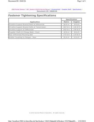
  • 1. 2009 Pontiac Solstice | SKY, Solstice (VIN M) Service Manual | Driveline/Axle | Propeller Shaft | Specifications | Document ID: 1868126 Fastener Tightening Specifications Application Specification Metric English Driveline Support Bracket Bolts at Differential 80 N·m 59 lb ft Driveline Support Bracket Bolts at Transmission 185 N·m 136 lb ft Driveline Support at Differential 200 N·m 148 lb ft Propeller Shaft C/V Flange Bolts - Front 40 N·m 30 lb ft Rear Differential Mounting Bolt 175 N·m 129 lb ft Rubber Couplings to Flanges - Rear 85 N·m 63 lb ft © 2010 General Motors Corporation. All rights reserved. Page 1 of 1Document ID: 1868126 2/22/2010http://localhost:9001/si/showDoc.do?docSyskey=1868126&pubCellSyskey=55239&pubO...
  • 2. 2009 Pontiac Solstice | SKY, Solstice (VIN M) Service Manual | Driveline/Axle | Propeller Shaft | Specifications | Document ID: 1522874 Adhesives, Fluids, Lubricants, and Sealers Application Type of Material GM Part Number United States Canada Propeller Shaft Centering Bushings Lubricant 1051344 993037 Propeller Shaft-to-Flange Bolts Threadlocker 12345493 10953488 © 2010 General Motors Corporation. All rights reserved. Page 1 of 1Document ID: 1522874 2/22/2010http://localhost:9001/si/showDoc.do?docSyskey=1522874&pubCellSyskey=64688&pubO...
  • 3. 2009 Pontiac Solstice | SKY, Solstice (VIN M) Service Manual | Driveline/Axle | Propeller Shaft | Repair Instructions | Document ID: 2100740 Propeller Shaft, Differential, and Driveline Support Replacement Special Tools J 44394 Axle Seal Protector Removal Procedure 1. Remove the left rear wheel drive shaft. Refer to Wheel Drive Shaft Replacement. 2. Remove the muffler and exhaust pipe. Refer to Exhaust Muffler Replacement. 3. Remove the floor panel tunnel panel front closeout panel. Refer to Floor Panel Tunnel Panel Replacement - Front. 4. Remove the floor panel tunnel rear panel. Refer to Floor Panel Tunnel Panel Replacement - Rear. 5. Support the transmission with a suitable jack stand. 6. Loosen, but DO NOT remove the driveline support to the transmission bolts (1). 7. Remove the transmission close out panel. Refer to Transmission Support Replacement. 8. Loosen, but DO NOT remove the left and right motor mount bolts. • For vehicles equipped with the 2.0L, refer to Engine Mount Replacement - Left Side and Engine Mount Replacement - Right Side. • For vehicles equipped with the 2.4L, refer to Engine Mount Replacement - Left Side and Engine Mount Replacement - Right Side. © 2010 General Motors Corporation. All rights reserved. Page 1 of 14Document ID: 2100740 2/22/2010http://localhost:9001/si/showDoc.do?docSyskey=2100740&pubCellSyskey=163575&pub...
  • 4. 9. Remove the front propeller shaft bolts (1) and washer support tabs (2) from the transmission. 10. Support the rear differential with a transmission jack stand. Page 2 of 14Document ID: 2100740 2/22/2010http://localhost:9001/si/showDoc.do?docSyskey=2100740&pubCellSyskey=163575&pub...
  • 5. Note: The proper nuts and bolts to be removed are those where the nut is the closest or facing the rear differential drive flange. DO NOT remove the nuts and bolt where the nuts are facing the front or propeller shaft. 11. Remove the propeller shaft nuts and bolts from the rear differential. 12. Remove the left (1) and right (2) rear differential mount bolts. 13. Lower the rear differential enough to clear the rear crossmember. 14. Install the J 44394 protector and move the rear differential to the left side of the vehicle to remove the right rear wheel drive shaft. Page 3 of 14Document ID: 2100740 2/22/2010http://localhost:9001/si/showDoc.do?docSyskey=2100740&pubCellSyskey=163575&pub...
  • 6. Note: DO NOT re-use the bolts, discard and use NEW only. 15. Remove the four differential carrier bracket bolts (1). 16. Separate the differential carrier (1) from the driveline support bracket (2). Page 4 of 14Document ID: 2100740 2/22/2010http://localhost:9001/si/showDoc.do?docSyskey=2100740&pubCellSyskey=163575&pub...
  • 7. 17. Remove the propeller shaft from the vehicle. Note: Steps 18 and 19 are for the replacing the driveline support. 18. Remove the driveline support bolts (1) and the washers (2) from the transmission. Page 5 of 14Document ID: 2100740 2/22/2010http://localhost:9001/si/showDoc.do?docSyskey=2100740&pubCellSyskey=163575&pub...
  • 8. 19. Remove the driveline support (1) from the transmission and the rear differential assembly. 20. If servicing the driveline support, remove the nut (1), bolt (2), and the washer block (3) from the driveline support. 21. Remove the driveline support (4) from the rear differential assembly. Page 6 of 14Document ID: 2100740 2/22/2010http://localhost:9001/si/showDoc.do?docSyskey=2100740&pubCellSyskey=163575&pub...
  • 9. Note: Support the right rear wheel drive shaft with mechanics wire. 22. If servicing the rear differential assembly, remove the rear differential assembly from the vehicle. Installation Procedure 1. Clean the bolt holes in the differential carrier with brake cleaner or other suitable solvents to remove any adhesive. 2. If servicing the driveline support, position the driveline support (4) on the differential housing. 3. Install the bolt plate (3), bolts (2) for the driveline support on the differential housing. Page 7 of 14Document ID: 2100740 2/22/2010http://localhost:9001/si/showDoc.do?docSyskey=2100740&pubCellSyskey=163575&pub...
  • 10. Caution: Refer to Component Fastener Tightening Caution in the Preface section. 4. Install the nuts (1) for the drive line support bolts (2) and tighten to 200 N·m (148 lb ft). 5. Position the driveline support (1) on the transmission. Note: Leave the driveline support bolts loose. 6. Install the driveline support bolts (1) and washers (2). Page 8 of 14Document ID: 2100740 2/22/2010http://localhost:9001/si/showDoc.do?docSyskey=2100740&pubCellSyskey=163575&pub...
  • 11. 7. Raise the differential to just below the rear crossmember. 8. Clean the pilot shaft (1) and the pilot hole (2) of any dirt or debris. 9. Apply a small amount of chassis lube on the pilot shaft (1). 10. Align the pilot shaft (1) and the pilot hole (2). Page 9 of 14Document ID: 2100740 2/22/2010http://localhost:9001/si/showDoc.do?docSyskey=2100740&pubCellSyskey=163575&pub...
  • 12. 11. Install the propeller shaft to the transmission and differential. Note: In steps 11 and 12, finger tighten the front and rear propeller shaft nuts and bolts only. DO NOT torque the propeller shaft nuts and bolts until the differential and driveline support have been aligned and torqued to specifications. 12. Install the propeller shaft bolts (1) and washer support tabs (2) in the transmission drive flange. Page 10 of 14Document ID: 2100740 2/22/2010http://localhost:9001/si/showDoc.do?docSyskey=2100740&pubCellSyskey=163575&pub...
  • 13. Note: Ensure that the driveline support bracket and the differential are properly joined. 13. Align the differential carrier (1) and the torque beam bracket (2). 14. Apply GM threadlocker to the NEW differential carrier bracket bolts (1). Refer to Adhesives, Fluids, Lubricants, and Sealers. Note: Use only hands tools to tighten the driveline support bolts. 15. Install the four new driveline support bracket bolts (1) and tighten to 80 N·m (59 lb ft). 16. Raise and position the differential in the rear support. Page 11 of 14Document ID: 2100740 2/22/2010http://localhost:9001/si/showDoc.do?docSyskey=2100740&pubCellSyskey=163575&pub...
  • 14. Note: Install the left and right rear differential bolts by hand before tightening to specifications. 17. Install the left (1) and right (2) rear differential bolt and tighten to 175 N·m (129 lb ft). 18. Tighten the rear propeller shaft bolts to 85 N·m (63 lb ft). 19. Tighten the front propeller shaft bolts in sequence (1-6) to 40 N·m (30 lb ft). 20. Install the left rear wheel drive shaft. Refer to Wheel Drive Shaft Replacement. Page 12 of 14Document ID: 2100740 2/22/2010http://localhost:9001/si/showDoc.do?docSyskey=2100740&pubCellSyskey=163575&pub...
  • 15. Note: Failing to perform the following service procedure will create the wrong driveline angle for the propeller shaft and alignment of the transmission and the rear differential. 21. Position a scale or known straight edge across the floor pan where the driveline tunnel closeout mounts to the body. 22. Position another scale at the transmission output shaft oil seal slinger. 23. Using the jack stand, raise or lower the transmission until a measurement of 80 mm (3.150 inch) is obtained. 24. Tighten the driveline support bolts (1) at the transmission to 185 N·m (136 lb ft). 25. Remove the jack stand from the rear differential. 26. Tighten the left and right motor mount bolts. • For vehicles equipped with the 2.0L, refer to Engine Mount Replacement - Left Side and Page 13 of 14Document ID: 2100740 2/22/2010http://localhost:9001/si/showDoc.do?docSyskey=2100740&pubCellSyskey=163575&pub...
  • 16. 27. Remove the transmission jack stand. 28. Install the transmission close out panel. Refer to Transmission Support Replacement. 29. Install the floor panel tunnel panel front closeout panel. Refer to Floor Panel Tunnel Panel Replacement - Front. 30. Install the floor panel tunnel rear panel. Refer to Floor Panel Tunnel Panel Replacement - Rear. 31. Install the muffler and exhaust pipe from the vehicle. Refer to Exhaust Muffler Replacement. Engine Mount Replacement - Right Side. • For vehicles equipped with the 2.4L, refer to Engine Mount Replacement - Left Side and Engine Mount Replacement - Right Side. Page 14 of 14Document ID: 2100740 2/22/2010http://localhost:9001/si/showDoc.do?docSyskey=2100740&pubCellSyskey=163575&pub...
  • 17. 2009 Pontiac Solstice | SKY, Solstice (VIN M) Service Manual | Driveline/Axle | Propeller Shaft | Repair Instructions | Document ID: 2101015 Propeller Shaft Replacement (Automatic) Removal Procedure 1. Raise and support the vehicle. Refer to Lifting and Jacking the Vehicle. 2. Remove the exhaust pipe and muffler. Refer to Muffler Replacement. 3. Remove the floor panel rear panel. Refer to Floor Panel Tunnel Panel Replacement - Rear. 4. Support the rear differential assembly with a suitable jack stand. 5. Remove the left (1) and right (2) rear differential support bolts. 6. Remove the front differential support bolt (1). © 2010 General Motors Corporation. All rights reserved. Page 1 of 5Document ID: 2101015 2/22/2010http://localhost:9001/si/showDoc.do?docSyskey=2101015&pubCellSyskey=55284&pubO...
  • 18. 7. Remove the propeller shaft bolts from the transmission output flange. 8. Remove the propeller shaft nut and bolts from the differential drive flange. 9. Lower the rear differential assembly enough to remove the propeller shaft from the vehicle. Installation Procedure 1. Remove all debris from the pilot shaft. 2. Apply a small amount of chassis lube on the pilot shaft and pilot shaft hole in the propeller shaft. 3. Position the propeller shaft on the transmission output flange. 4. Raise the rear differential at the same time as aligning the propeller shaft pilot shaft and the propeller shaft pilot hole. Page 2 of 5Document ID: 2101015 2/22/2010http://localhost:9001/si/showDoc.do?docSyskey=2101015&pubCellSyskey=55284&pubO...
  • 19. Note: DO NOT tighten the propeller shaft front or rear fasteners until the front and rear differential support bolts are tighten to specifications. 5. Hand tighten the propeller shaft bolts to the transmission output shaft flange. 6. Hand tighten the nuts and bolts to the rear differential drive flange. 7. Position the rear differential assembly in the support. Caution: Refer to Fastener Caution in the Preface section. Page 3 of 5Document ID: 2101015 2/22/2010http://localhost:9001/si/showDoc.do?docSyskey=2101015&pubCellSyskey=55284&pubO...
  • 20. 8. Install the left (1) and right (2) rear differential support bolts and tighten to 175 N·m (129 lb ft). 9. Install the front differential support bolt (1) and tighten to 175 N·m (129 lb ft). 10. Remove the jack stand from the rear differential assembly. Page 4 of 5Document ID: 2101015 2/22/2010http://localhost:9001/si/showDoc.do?docSyskey=2101015&pubCellSyskey=55284&pubO...
  • 21. 11. Tighten the front propeller shaft bolts in sequence 1-6 to 40 N·m (30 lb ft). 12. Tighten the rear propeller shaft bolts and tighten to 85 N·m (63 lb ft). 13. Install the floor panel rear panel. Refer to Floor Panel Tunnel Panel Replacement - Rear. 14. Install the exhaust pipe and muffler. Refer to Muffler Replacement. 15. Remove the support and lower the vehicle. Page 5 of 5Document ID: 2101015 2/22/2010http://localhost:9001/si/showDoc.do?docSyskey=2101015&pubCellSyskey=55284&pubO...
  • 22. 2009 Pontiac Solstice | SKY, Solstice (VIN M) Service Manual | Driveline/Axle | Propeller Shaft | Repair Instructions | Document ID: 2157340 Propeller Shaft Replacement (RPO ZOK) Callout Component Name Preliminary Procedures 1. Remove the floor panel tunnel rear panel. Refer to Floor Panel Tunnel Panel Replacement - Rear. 2. Support the rear drive module (RDM). 3. Remove the bolt from the differential case bracket assembly to body. 1 Propeller Shaft Coupling Nut (Qty: 3) Caution: Refer to Fastener Caution in the Preface section. Tip Tighten 85 N·m (63 lb ft) • DO NOT remove the bolts from the coupler to the propeller shaft. Remove only the bolts from the coupler to the drive axle pinion flange. • Clean the threads and apply LOCTITE. Refer to Adhesives, Fluids, Lubricants, and Sealers. 2 Propeller Shaft Coupler Bolt (Qty: 3) © 2010 General Motors Corporation. All rights reserved. Page 1 of 2Document ID: 2157340 2/22/2010http://localhost:9001/si/showDoc.do?docSyskey=2157340&pubCellSyskey=55284&pubO...
  • 23. 3 CV Joint Mounting Bolt (Qty: 6) Tip Tighten 40 N·m (30 lb ft) • The CV joint mounting bolts MUST be tightened in a star pattern sequence. • Clean the threads and apply LOCTITE. Refer to Adhesives, Fluids, Lubricants, and Sealers. 4 CV Joint Mounting Bolt Spacer 5 Propeller Shaft Tip • Before installation, apply a small amount of lubricant to the front and rear propeller shaft center bushings. Refer to Adhesives, Fluids, Lubricants, and Sealers. • Lower the front of the RDM to remove the propeller shaft from the pinion flange. Page 2 of 2Document ID: 2157340 2/22/2010http://localhost:9001/si/showDoc.do?docSyskey=2157340&pubCellSyskey=55284&pubO...
  • 24. 2009 Pontiac Solstice | SKY, Solstice (VIN M) Service Manual | Driveline/Axle | Rear Drive Axle | Specifications | Document ID: 1868149 Fastener Tightening Specifications Fastener Tightening Specifications Application Specification Metric English Differential Carrier Bracket to Bracket Reinforcement Bolt (Automatic only) 175 N·m 129 lb ft Differential Carrier Bracket Reinforcement (Automatic only) 110 N·m + 20 degrees -- Driveline Support to Driveline Support Bracket Bolts (Manual Only) 200 N·m 148 lb ft Driveline Support Bracket to Differential Bolts 80 N·m 59 lb ft Differential Carrier Cover Bolts 25 N·m 18 lb ft Differential Ring Gear Bolts 185 N·m 136 lb ft Differential Drain Plug 35 N·m 26 lb ft Differential Drive Pinion Flange Nut 245 N·m 181 lb ft Differential Fill Plug 35 N·m 26 lb ft Differential Rear Mounting Bolts 175 N·m 129 lb ft Propeller Shaft Coupler-to-Differential Flange Bolts 85 N·m 63 lb ft Propeller Shaft to Transmission Output Shaft Bolts 40 N·m 30 lb ft © 2010 General Motors Corporation. All rights reserved. Page 1 of 1Document ID: 1868149 2/22/2010http://localhost:9001/si/showDoc.do?docSyskey=1868149&pubCellSyskey=55636&pubO...
  • 25. 2009 Pontiac Solstice | SKY, Solstice (VIN M) Service Manual | Driveline/Axle | Rear Drive Axle | Specifications | Document ID: 1702638 Lubrication Specifications Capacities Application Quantity Metric English Synthetic Differential Lubricant GL-5 75W90 G/M P/N 89021677 (Canadian P/N 89021678) l Drain and Fill, if differential side cover has been removed to service any internal differential component. For vehicles equipped the Limited Slip Differential 1.2 L 1.26 Qt For vehicles not equipped with the Limited Slip Differential 1.3 L 1.3 Qt l Drain and Fill with use of drain plug. 1.1 L 1.16 Qt Important: The following is for vehicles equipped with the Limited Slip Differential option. The Limited Slip Additive container capacity is greater than the amount needed. Only add the amount specified. Limited Slip Differential Lubricant Additive GM P/N 1052358 (Canadian P/N 992694) l Drain and Fill with cover removed. 100 ml 3.38 oz l Drain and Fill with use of drain plug. 70 ml 2.37 oz © 2010 General Motors Corporation. All rights reserved. Page 1 of 1Document ID: 1702638 2/22/2010http://localhost:9001/si/showDoc.do?docSyskey=1702638&pubCellSyskey=55652&pubO...
  • 26. 2009 Pontiac Solstice | SKY, Solstice (VIN M) Service Manual | Driveline/Axle | Rear Drive Axle | Specifications | Document ID: 1768573 Rear Axle Specifications Application Specification Metric English Differential Case Shim Sizes 3.5-4.4 mm 0.14-0.17 in Pinion Housing Shim Sizes 1.2-1.9 mm 0.04-0.07 in Pinion Rotating Torque w/Seals 2.5-4 N·m 22-35 lb in Ring Gear/Pinion A1 Nominal Value - All Axles 111.00 mm 4.37 in Ring Gear/Pinion A2 Nominal Value - 3.91 Ratio Axle 63.5 mm 2.50 in Torsional Backlash l 3.91 Ratio Axle with 105 mm Flange 0.25-0.41 mm 0.010-0.016 in © 2010 General Motors Corporation. All rights reserved. Page 1 of 1Document ID: 1768573 2/22/2010http://localhost:9001/si/showDoc.do?docSyskey=1768573&pubCellSyskey=55767&pubO...
  • 27. 2009 Pontiac Solstice | SKY, Solstice (VIN M) Service Manual | Driveline/Axle | Rear Drive Axle | Specifications | Document ID: 1768587 Rear Axle Usage (1) Ratio (2) GM Part Number (3) Getrag Part Number (4) Serial Number Available Axle Ratios Axle Ratio Drive/Engine Flange Size 3:91 RWD/2.4L L4 105 mm © 2010 General Motors Corporation. All rights reserved. Page 1 of 1Document ID: 1768587 2/22/2010http://localhost:9001/si/showDoc.do?docSyskey=1768587&pubCellSyskey=55786&pubO...
  • 28. 2009 Pontiac Solstice | SKY, Solstice (VIN M) Service Manual | Driveline/Axle | Rear Drive Axle | Specifications | Document ID: 784775 Adhesives, Fluids, Lubricants, and Sealers Application Type of Material GM Part Number US Canada Rear Differential Lubricant Axle Lubricant (Synthetic) 12378261 10953455 Pinion Nut Thread Locker 12345382 10953489 © 2010 General Motors Corporation. All rights reserved. Page 1 of 1Document ID: 784775 2/22/2010http://localhost:9001/si/showDoc.do?docSyskey=784775&pubCellSyskey=55680&pubObj...
  • 29. 2009 Pontiac Solstice | SKY, Solstice (VIN M) Service Manual | Driveline/Axle | Rear Drive Axle | Visual Identification | Document ID: 2001093 Rear Axle Identification (1) Axle Ratio (2) GM Part Number (3) Bar Code (4) Getrag Logo (5) Getrag Part Number (6) Getrag Serial Number (7) GM Logo © 2010 General Motors Corporation. All rights reserved. Page 1 of 1Document ID: 2001093 2/22/2010http://localhost:9001/si/showDoc.do?docSyskey=2001093&pubCellSyskey=55666&pubO...
  • 30. 2009 Pontiac Solstice | SKY, Solstice (VIN M) Service Manual | Driveline/Axle | Rear Drive Axle | Component Locator | Document ID: 1387527 Limited Slip Differential Disassembled Views Differential Components (101) Bearing (101) Bearing (102) Bolt (103) Differential Shaft (104) Left Case Half (105) Right Case Half (106) Ring Gear (107) Axle Side Gear (107) Axle Side Gear (108) Beveled Washer (109) Plate/Separator (109) Plate/Separator (110) Clutch Pack (110) Clutch Pack (111) Pinion Gear (111) Pinion Gear (112) Washer © 2010 General Motors Corporation. All rights reserved. Page 1 of 2Document ID: 1387527 2/22/2010http://localhost:9001/si/showDoc.do?docSyskey=1387527&pubCellSyskey=150340&pub...
  • 31. (112) Washer Page 2 of 2Document ID: 1387527 2/22/2010http://localhost:9001/si/showDoc.do?docSyskey=1387527&pubCellSyskey=150340&pub...
  • 32. 2009 Pontiac Solstice | SKY, Solstice (VIN M) Service Manual | Driveline/Axle | Rear Drive Axle | Component Locator | Document ID: 1792398 Rear Axle Disassembled Views (1) Differential Carrier (2) Carrier Cover (3) Pinion Bearing Gage (4) Nut (5) Flange (6) Pinion Oil Seal (7) Bearing (8) Cup (9) Bolt (10) Shim (11) O-ring Seal (12) Pinion Bearing Spacer (13) Cup (14) Bearing (15) Bolt (16) Differential Carrier Bracket (17) Axle Oil Seal (17) Axle Oil Seal © 2010 General Motors Corporation. All rights reserved. Page 1 of 2Document ID: 1792398 2/22/2010http://localhost:9001/si/showDoc.do?docSyskey=1792398&pubCellSyskey=55801&pubO...
  • 33. (18) Drain Plug (19) Shim (19) Shim (20) Cup (20) Cup (21) O-ring Seal (22) Vent (23) Fill Plug (24) Bolt (25) Fill Plug Washer (100) Differential Assembly (110) Pinion Gear Page 2 of 2Document ID: 1792398 2/22/2010http://localhost:9001/si/showDoc.do?docSyskey=1792398&pubCellSyskey=55801&pubO...
  • 34. 2009 Pontiac Solstice | SKY, Solstice (VIN M) Service Manual | Driveline/Axle | Rear Drive Axle | Repair Instructions | Document ID: 2101300 Rear Axle Lubricant Level Inspection 1. Raise and support the vehicle. Refer to Lifting and Jacking the Vehicle. 2. Clean any dirt from around the differential fill plug. 3. Remove the fill plug from the differential and drain the fluid. 4. Check the differential fluid level. It should be even with the bottom of the fill plug hole to no lower than 6 mm (0.25 in) below the opening. 5. Add new fluid if necessary. 6. Fill the differential with 75W90 synthetic axle lubricant. Refer to Approximate Fluid Capacities and Lubrication Specifications. Caution: Refer to Fastener Caution in the Preface section. 7. Install the differential fill plug to the differential and tighten to 35 N·m (26 lb ft). 8. Lower the vehicle. © 2010 General Motors Corporation. All rights reserved. Page 1 of 1Document ID: 2101300 2/22/2010http://localhost:9001/si/showDoc.do?docSyskey=2101300&pubCellSyskey=69628&pubO...
  • 35. 2009 Pontiac Solstice | SKY, Solstice (VIN M) Service Manual | Driveline/Axle | Rear Drive Axle | Repair Instructions | Document ID: 2101301 Axle Lubricant Change Draining Procedure 1. Raise and support the vehicle. Refer to Lifting and Jacking the Vehicle. 2. Clean any dirt from around the differential drain plug. 3. Position a drain pan under drain plug. 4. Remove the drain plug from the differential and drain the fluid. Filling Procedure Caution: Refer to Fastener Caution in the Preface section. © 2010 General Motors Corporation. All rights reserved. Page 1 of 3Document ID: 2101301 2/22/2010http://localhost:9001/si/showDoc.do?docSyskey=2101301&pubCellSyskey=55648&pubO...
  • 36. 1. Install the drain plug to the differential and tighten to 35 N·m (26 lb ft).. 2. Clean any dirt from around the differential fill plug. 3. Remove the fill plug from the differential. Note: If equipped with a limited slip differential, limited slip differential lubricant additive, GM P/N 1052358 (Canadian P/N 992694) or equivalent must be added first. Refer to Lubrication Specifications . Approximately 0.23 L (7.8 oz) of residual fluid will remain in the differential. 4. Fill the differential with 75W90 synthetic axle lubricant, GM P/N 12378261 (Canadian P/N 10953455) or equivalent. Refer to Lubrication Specifications. 5. Inspect the gear lubricant level to ensure it is even with the bottom of the fill plug hole to no lower than 6 mm (0.25 in) below the opening. Page 2 of 3Document ID: 2101301 2/22/2010http://localhost:9001/si/showDoc.do?docSyskey=2101301&pubCellSyskey=55648&pubO...
  • 37. 6. Install the fill plug to the differential and tighten to 35 N·m (26 lb ft). 7. Lower the vehicle. Page 3 of 3Document ID: 2101301 2/22/2010http://localhost:9001/si/showDoc.do?docSyskey=2101301&pubCellSyskey=55648&pubO...
  • 38. 2009 Pontiac Solstice | SKY, Solstice (VIN M) Service Manual | Driveline/Axle | Rear Drive Axle | Repair Instructions | Document ID: 2101303 Differential Carrier Cover and Seal Replacement - Left Side Removal Procedure 1. Remove the rear differential. Refer to Differential Replacement. 2. Remove the 9 carrier cover bolts (6). 3. Using the pry tabs (4, 5, 7), remove the carrier cover (3) from the differential carrier (1). 4. Remove the O-ring seal (2) from the cover (3). Installation Procedure © 2010 General Motors Corporation. All rights reserved. Page 1 of 2Document ID: 2101303 2/22/2010http://localhost:9001/si/showDoc.do?docSyskey=2101303&pubCellSyskey=55822&pubO...
  • 39. 1. Install the housing cover O-ring (2) into the groove on the housing cover (3). 2. Apply a light coat of oil to the housing cover O-ring (2) and install the housing cover (3) onto the housing (1). Caution: Refer to Fastener Caution in the Preface section. 3. Install the 9 side cover bolts (4) and tighten in a criss-cross pattern to 29 N·m (21 lb ft). 4. Install the rear differential. Refer to Differential Replacement. Page 2 of 2Document ID: 2101303 2/22/2010http://localhost:9001/si/showDoc.do?docSyskey=2101303&pubCellSyskey=55822&pubO...
  • 40. 2009 Pontiac Solstice | SKY, Solstice (VIN M) Service Manual | Driveline/Axle | Rear Drive Axle | Repair Instructions | Document ID: 1583106 Output Shaft Seal Replacement Tools Required J 45017 Output Shaft Seal Installer Removal Procedure 1. Raise and suitably support the vehicle. Refer to Lifting and Jacking the Vehicle . 2. Remove the appropriate rear tire and wheel assembly. Refer to Tire and Wheel Removal and Installation . 3. Remove the appropriate wheel drive shaft. Refer to Wheel Drive Shaft Replacement . 4. Using a flat bladed tool remove the differential output shaft seal. Take care not to damage any sealing surfaces. Installation Procedure 1. Lubricate the wheel drive shaft sealing surface of the oil seal with 75W90 synthetic axle lubricant, GM P/N 12378261 (Canadian P/N 10953455) or equivalent. 2. Install the differential output shaft seal (2) to the J 45017 . 3. Using the J 45017 (1), install the differential output shaft seal (2). 4. Remove J 45017 (1) from the differential output shaft seal (2). 5. Install the wheel drive shaft. Refer to Wheel Drive Shaft Replacement . 6. Inspect the fluid level. Refer to Rear Axle Lubricant Level Inspection . 7. Install the rear tire and wheel assembly. Refer to Tire and Wheel Removal and Installation . 8. Lower the vehicle. © 2010 General Motors Corporation. All rights reserved. Page 1 of 1Document ID: 1583106 2/22/2010http://localhost:9001/si/showDoc.do?docSyskey=1583106&pubCellSyskey=55800&pubO...
  • 41. 2009 Pontiac Solstice | SKY, Solstice (VIN M) Service Manual | Driveline/Axle | Rear Drive Axle | Repair Instructions | Document ID: 2157343 Drive Pinion Flange/Yoke and/or Oil Seal Replacement Special Tools Removal Procedure 1. Raise and support the vehicle. Refer to Lifting and Jacking the Vehicle. 2. Remove the floor panel tunnel rear panel. Refer to Floor Panel Tunnel Panel Replacement - Rear. Note: The following service procedure is for those vehicles equipped with a manual transmission and drive line support. For vehicles equipped with a automatic transmission, proceed to step 4. 3. Remove the propeller shaft, differential and driveline support. Refer to Propeller Shaft, Differential, and Driveline Support Replacement. Note: Remove only the propeller shaft coupler to differential flange bolts. DO NOT remove the coupler from the propeller shaft. 4. Remove the propeller shaft from the rear differential. Refer to Propeller Shaft Replacement. 5. Carefully position the propeller shaft to the side and support using a suitable jack stand. 6. Remove the differential carrier bracket. Refer to Differential Carrier Bracket Replacement • J 34826 Hub Nut Socket (36 mm) • J 42851 Front Cover Oil Seal Installer • J 45012 Holding Fixture • J 45019 Flange and Pinion Cage Remover © 2010 General Motors Corporation. All rights reserved. Page 1 of 4Document ID: 2157343 2/22/2010http://localhost:9001/si/showDoc.do?docSyskey=2157343&pubCellSyskey=55807&pubO...
  • 42. 7. Install the J 45012 to the flange. 8. While holding the J 45012 , remove the drive pinion nut using the J 34826 . 9. Remove the J 45012 from the flange. 10. Install the J 45019 to the flange. 11. Using the J 45019 , remove the flange. 12. Using a flat-bladed tool, remove the drive pinion seal. care not to damage any of the sealing surfaces. Installation Procedure Note: Ensure that the pinion bore is free of dirt and debris. 1. Apply a small amount of synthetic gear oil GM P/N 121378514 (Canadian P/N 88901045) or equivalent to the surface of the drive pinion flange and the drive pinion seal. Page 2 of 4Document ID: 2157343 2/22/2010http://localhost:9001/si/showDoc.do?docSyskey=2157343&pubCellSyskey=55807&pubO...
  • 43. 2. Install the drive pinion seal to the J 42851 . 3. Using the J 42851 (1) , install the drive pinion seal (2) in the differential (3). 4. Remove the J 45019 (1). 5. Install the J 45012 . 6. Install the pinion flange to the drive pinion shaft. Note: The pinion shaft threads and pinion flange nut must be free of residue and debris prior to application of the threadlocker. 7. Clean all the residue from the pinion shaft threads and the pinion flange nut by using denatured alcohol or equivalent and allow to dry. Note: Ensure that there are no gaps in the threadlocker along the length of the filled area of the pinion shaft threads. 8. Apply the threadlocker GM P/N 12345382 (Canadian P/N 10953489) or equivalent to 2/3 of the threads length of the pinion shaft threads. 9. Allow the threadlocker to cure approximately 10 minutes before installation. Caution: Refer to Fastener Caution in the Preface section. 10. Install the drive pinion flange nut to the pinion shaft. While holding the J 45012 , use the J 34826 to tighten the drive pinion nut. Tighten Tighten the pinion flange nut to 245 N·m (181 lb ft). 11. Remove the J 45012 . 12. Install the differential carrier bracket. Refer to Differential Carrier Bracket Replacement Page 3 of 4Document ID: 2157343 2/22/2010http://localhost:9001/si/showDoc.do?docSyskey=2157343&pubCellSyskey=55807&pubO...
  • 44. Note: The following service procedure is for those vehicles equipped with a manual transmission and drive line support. For vehicles equipped with a automatic transmission, proceed to step 15. 13. Install the propeller shaft, differential and driveline support. Refer to Propeller Shaft, Differential, and Driveline Support Replacement. 14. Install the propeller shaft to the differential. Refer to Propeller Shaft Replacement. 15. Install the floor panel tunnel rear panel. Refer to Floor Panel Tunnel Panel Replacement - Rear. 16. Inspect the fluid level Refer to Rear Axle Lubricant Level Inspection. 17. Remove the support and lower the vehicle. Page 4 of 4Document ID: 2157343 2/22/2010http://localhost:9001/si/showDoc.do?docSyskey=2157343&pubCellSyskey=55807&pubO...
  • 45. 2009 Pontiac Solstice | SKY, Solstice (VIN M) Service Manual | Driveline/Axle | Rear Drive Axle | Repair Instructions | Document ID: 2151286 Differential Carrier Bracket Replacement Removal Procedure Note: Some portions of the frame and under body have been removed for the clarity of the location of the differential carrier bracket. 1. Raise and support the vehicle. Refer to Lifting and Jacking the Vehicle. 2. Remove the floor panel tunnel rear panel. Refer to Floor Panel Tunnel Panel Replacement - Rear. 3. Support the rear differential carrier assembly with a suitable jack stand. © 2010 General Motors Corporation. All rights reserved. Page 1 of 4Document ID: 2151286 2/22/2010http://localhost:9001/si/showDoc.do?docSyskey=2151286&pubCellSyskey=143204&pub...
  • 46. 4. Remove the differential mounting bracket bolt (1) frame bracket. Note: The following service procedure is to allow for enough clearance to remove the differential mounting bracket. 5. Loosen the 2 frame bracket bolts (2). Note: DO NOT re-use the differential carrier bracket bolts. Discard and use NEW only. 6. Remove the 4 differential carrier mounting bracket bolts (1). 7. Remove the differential carrier mounting bracket (2). Installation Procedure 1. Remove any thread locker from the bolt holes in the differential carrier with brake clean or equivalent. Page 2 of 4Document ID: 2151286 2/22/2010http://localhost:9001/si/showDoc.do?docSyskey=2151286&pubCellSyskey=143204&pub...
  • 47. 2. Position the differential carrier bracket (2) on the differential. 3. Apply GM threadlocker P/N 89021297 (Canadian P/N 10953488) or equivalent to the NEW differential carrier bracket bolts (1). Caution: Refer to Fastener Caution in the Preface section. 4. Install the 4 NEW differential carrier bracket bolts (1) and tighten to 80 N·m (59 lb ft). 5. Hand tighten the differential frame bracket to differential carrier bolt (1). 6. Install the 2 differential carrier bracket to frame bolts (2) and tighten to 110 N·m (81 lb ft) plus 20 degrees. 7. Tighten the differential carrier bracket bolt (1) to 175 N·m (122 lb ft). Page 3 of 4Document ID: 2151286 2/22/2010http://localhost:9001/si/showDoc.do?docSyskey=2151286&pubCellSyskey=143204&pub...
  • 48. 8. Remove the jack stand. 9. Install the floor panel tunnel rear panel. Refer to Floor Panel Tunnel Panel Replacement - Rear. 10. Remove the support and lower the vehicle. Page 4 of 4Document ID: 2151286 2/22/2010http://localhost:9001/si/showDoc.do?docSyskey=2151286&pubCellSyskey=143204&pub...
  • 49. 2009 Pontiac Solstice | SKY, Solstice (VIN M) Service Manual | Driveline/Axle | Rear Drive Axle | Repair Instructions | Document ID: 2101310 Differential Replacement Removal Procedure 1. Raise and support the vehicle. Refer to Lifting and Jacking the Vehicle. 2. Remove propeller shaft. Refer to Propeller Shaft Replacement. 3. Remove the rear tire and wheel assemblies. Refer to Tire and Wheel Removal and Installation. 4. Remove the right and left wheel drive shafts. Refer to Wheel Drive Shaft Replacement. 5. Position a transmission jack beneath the differential. 6. Firmly secure the differential to the transmission jack. © 2010 General Motors Corporation. All rights reserved. Page 1 of 4Document ID: 2101310 2/22/2010http://localhost:9001/si/showDoc.do?docSyskey=2101310&pubCellSyskey=55773&pubO...
  • 50. 7. Remove the front differential carrier bracket-to-frame bolt (1). 8. Remove the left (1) and right (2) differential rear mounting bolts. 9. Lower the jack slightly until the mounting ear at the front of the differential clears the support attachment point. 10. Remove the differential from the vehicle. Installation Procedure Note: The differential is shipped with a plastic vent plug. Remove the plastic vent plug prior to differential vent installation. 1. When replacing the differential. remove the plastic vent plug and install a new differential vent. The vent flange must be fully seated. 2. With the differential firmly attached to the jack, raise the differential to the vehicle. Page 2 of 4Document ID: 2101310 2/22/2010http://localhost:9001/si/showDoc.do?docSyskey=2101310&pubCellSyskey=55773&pubO...
  • 51. 3. Hand install the differential carrier bracket-to-frame bolt (1) in order to locate the differential to the rear support. 4. With the differential firmly attached to the jack, raise the differential to the rear support. 5. Position the differential to the support. Caution: Refer to Fastener Caution in the Preface section. Page 3 of 4Document ID: 2101310 2/22/2010http://localhost:9001/si/showDoc.do?docSyskey=2101310&pubCellSyskey=55773&pubO...
  • 52. 6. Install the left (1) and right (2) differential rear mounting bolt (1) and tighten to 175 N·m (129 lb ft). 7. Tighten the differential carrier bracket to frame bolt and tighten to 175 N·m (129 lb ft). 8. Remove the transmission jack. 9. Install propeller shaft. Refer to Propeller Shaft Replacement. 10. Install the wheel drive shafts. Refer to Wheel Drive Shaft Replacement. 11. Install the rear tire and wheel assemblies. Refer to Tire and Wheel Removal and Installation. 12. Inspect the differential lubricant level. Refer to Rear Axle Lubricant Level Inspection. 13. Lower the vehicle. Page 4 of 4Document ID: 2101310 2/22/2010http://localhost:9001/si/showDoc.do?docSyskey=2101310&pubCellSyskey=55773&pubO...
  • 53. 2009 Pontiac Solstice | SKY, Solstice (VIN M) Service Manual | Driveline/Axle | Rear Drive Axle | Repair Instructions | Document ID: 2006080 Limited Slip Differential Disassemble Special Tools J 42162 Getrag Axle Side Gear Compressor 1. Remove the 10 ring gear bolts (1) and the ring gear (3) from the differential carrier (2) using a punch and a hammer through the bolt hole. Discard the ring gear bolt (1). 2. Pry the halves apart using the pry points. © 2010 General Motors Corporation. All rights reserved. Page 1 of 6Document ID: 2006080 2/22/2010http://localhost:9001/si/showDoc.do?docSyskey=2006080&pubCellSyskey=150376&pub...
  • 54. Important: Friction discs and separator plates develop specific wear patterns. During disc and plate removal, keep the components in the order in which they were removed. 3. Remove the axle side gear (107) and clutch pack (110) from the right half (105). 4. Remove the clutch pack and axle gear from the right half. Note the thick pressure plate (109) side that has friction material faces away from the gear teeth. Page 2 of 6Document ID: 2006080 2/22/2010http://localhost:9001/si/showDoc.do?docSyskey=2006080&pubCellSyskey=150376&pub...
  • 55. 5. Remove the beveled washer from the axle side gear. Note that the orientation of the beveled washer (108) faces out. 6. Tag the clutch pack (110) to indicate the position of the components. Page 3 of 6Document ID: 2006080 2/22/2010http://localhost:9001/si/showDoc.do?docSyskey=2006080&pubCellSyskey=150376&pub...
  • 56. 7. Using the J 42162 and a press as shown, apply light pressure so the differential shaft can be removed. 8. Remove the differential shaft (103). Release pressure from the press. Page 4 of 6Document ID: 2006080 2/22/2010http://localhost:9001/si/showDoc.do?docSyskey=2006080&pubCellSyskey=150376&pub...
  • 57. 9. Remove the pinion gears (111) and washers (112). 10. Remove the clutch pack and axle gear from the left half. Note the thick pressure plate (109) side that has friction material faces away from the gear teeth. Page 5 of 6Document ID: 2006080 2/22/2010http://localhost:9001/si/showDoc.do?docSyskey=2006080&pubCellSyskey=150376&pub...
  • 58. 11. Remove the beveled washer from the axle side gear. Note that the orientation of the beveled washer (108) faces out. 12. Tag the clutch pack (110) to indicate the position of the components. Page 6 of 6Document ID: 2006080 2/22/2010http://localhost:9001/si/showDoc.do?docSyskey=2006080&pubCellSyskey=150376&pub...
  • 59. 2009 Pontiac Solstice | SKY, Solstice (VIN M) Service Manual | Driveline/Axle | Rear Drive Axle | Repair Instructions | Document ID: 2101312 Limited Slip Differential Cleaning and Inspection Warning: Refer to Safety Glasses Warning in the Preface section. 1. Clean all parts with an approved solvent. 2. Visually inspect all the parts for excessive wear or breakage. Replace the parts if necessary. 3. Inspect the pinion gear and the side gear teeth for any of the following conditions: 4. Inspect the thrust washers (112) for wear. 5. Inspect the fit of the side gears (107, 111) on the axle shafts. 6. Inspect the differential case (104, 105) for cracks and scoring. 7. Inspect the side gear bore for scoring. If scoring is present, replace the entire differential. 8. Replace the differential if there is damage to the case. • Wear • Cracks • Scoring • Spalling © 2010 General Motors Corporation. All rights reserved. Page 1 of 1Document ID: 2101312 2/22/2010http://localhost:9001/si/showDoc.do?docSyskey=2101312&pubCellSyskey=150380&pub...
  • 60. 2009 Pontiac Solstice | SKY, Solstice (VIN M) Service Manual | Driveline/Axle | Rear Drive Axle | Repair Instructions | Document ID: 2161071 Limited Slip Differential Assemble Special Tools J 42162 Getrag Axle Side Gear Compressor 1. Install a beveled washer (108) on the axle side gear with bevel facing out. 2. Install a thick pressure plate (109) with friction material facing away from the gear teeth. © 2010 General Motors Corporation. All rights reserved. Page 1 of 4Document ID: 2161071 2/22/2010http://localhost:9001/si/showDoc.do?docSyskey=2161071&pubCellSyskey=150385&pub...
  • 61. Note: Friction discs and separator plates develop specific wear patterns. During disc and plate installation, keep the components in the order in which they were removed. 3. Install the steel plate against friction material of the pressure plate. Alternate the installation of steel plates and friction discs. Ensure that the last steel plate of the clutch pack (110) is against the case half. 4. Repeat steps 1 through 3 for the other side. 5. Install the assembled axle side gear (107) into the right case half (105). 6. Align tabs on the steel plates to fit the grooves. Page 2 of 4Document ID: 2161071 2/22/2010http://localhost:9001/si/showDoc.do?docSyskey=2161071&pubCellSyskey=150385&pub...
  • 62. 7. Install the assembled axle side gear (107) into the left case half (104). 8. Align tabs on the steel plates to fit the grooves. Note: When using the hydraulic press, apply light pressure on the pinion gears and washers so they align with the pinion differential shaft bores. 9. Using the J 42162 compressor and a press, install the pinion gears and washers. 10. Install the differential shaft (103) ensuring that it moves through the washers and gears properly. Page 3 of 4Document ID: 2161071 2/22/2010http://localhost:9001/si/showDoc.do?docSyskey=2161071&pubCellSyskey=150385&pub...
  • 63. 11. Align bolt holes between the halves and lightly press them together. 12. Install the ring gear (2) into the differential carrier (3). 13. Install 10 NEW ring gear bolts (1) in order to align the gear to the hub. Hand tighten at this time. Caution: Refer to Fastener Caution in the Preface section. 14. Tighten the ring gear bolts to 185 N·m (136 lb ft) Page 4 of 4Document ID: 2161071 2/22/2010http://localhost:9001/si/showDoc.do?docSyskey=2161071&pubCellSyskey=150385&pub...
  • 64. 2009 Pontiac Solstice | SKY, Solstice (VIN M) Service Manual | Driveline/Axle | Wheel Drive Shafts | Specifications | Document ID: 1583120 Fastener Tightening Specifications Application Specification Metric English Wheel Drive Shaft Nut 215 N·m 159 lb ft © 2010 General Motors Corporation. All rights reserved. Page 1 of 1Document ID: 1583120 2/22/2010http://localhost:9001/si/showDoc.do?docSyskey=1583120&pubCellSyskey=61769&pubO...
  • 65. 2009 Pontiac Solstice | SKY, Solstice (VIN M) Service Manual | Driveline/Axle | Wheel Drive Shafts | Component Locator | Document ID: 1596917 Wheel Drive Shafts Disassembled Views Wheel Drive Shafts Disassembled Views (1) Shaft Clamp (2) Outer Joint Seal (3) Boot Insert (4) Joint Clamp (5) Retaining Ring, Large (6) Retaining Ring, Small (7) Can, Joint (8) Outer Joint Assembly (9) Bar, Wheel Drive Shaft (10) Shaft Clamp © 2010 General Motors Corporation. All rights reserved. Page 1 of 2Document ID: 1596917 2/22/2010http://localhost:9001/si/showDoc.do?docSyskey=1596917&pubCellSyskey=61791&pubO...
  • 66. (11) Inner Joint Seal (12) Joint Clamp (13) Inner Joint Assembly Page 2 of 2Document ID: 1596917 2/22/2010http://localhost:9001/si/showDoc.do?docSyskey=1596917&pubCellSyskey=61791&pubO...
  • 67. 2009 Pontiac Solstice | SKY, Solstice (VIN M) Service Manual | Driveline/Axle | Wheel Drive Shafts | Repair Instructions | Document ID: 2099181 Wheel Drive Shaft Replacement Special Tools Removal Procedure Note: In the following service procedure the left side is shown, the right side is similar. 1. Raise and support the vehicle. Refer to Lifting and Jacking the Vehicle. 2. Remove the tire and wheel assembly. Refer to Tire and Wheel Removal and Installation. 3. Remove the rear brake rotor. Refer to Rear Brake Rotor Replacement. Note: The wheel drive shaft spindle nut must not be reused. Replace the wheel drive shaft spindle nut with a new nut whenever it is removed. 4. Remove and discard the wheel drive shaft spindle nut. 5. Using J-42129 Wheel Hub Remover , CJ129 Universal Hub Puller - Snap-On, 7394 Universal Hub Puller - OTC, or equivalent, disengage the wheel drive shaft from the wheel bearing/hub. 6. Remove the adjustment link. Refer to Adjust Link Replacement. 7. Separate the upper ball joint from the rear knuckle. Refer to Knuckle Replacement. • J-42129 Wheel Hub Remover • J-44394 Seal Protector © 2010 General Motors Corporation. All rights reserved. Page 1 of 6Document ID: 2099181 2/22/2010http://localhost:9001/si/showDoc.do?docSyskey=2099181&pubCellSyskey=61782&pubO...
  • 68. 8. Using a suitable tool, carefully release the wheel drive shaft from the rear differential enough to install the J-44394 Seal Protector . Caution: J-44394 must be installed into the differential output shaft seal prior to removing and installing the wheel drive shaft. Failure to install J-44394 as indicated may cause the splines of the wheel drive shaft to cut the differential output seal. 9. Carefully install the J-44394 Protector over the wheel drive shaft. 10. Carefully slide the J-44394 Protector into the differential output shaft seal. 11. Remove the wheel drive shaft from the vehicle. 12. If reusing the wheel drive shaft, remove and discard the wheel drive shaft retaining ring. The wheel drive shaft retaining ring is on the splined shaft of the cross groove joint. Page 2 of 6Document ID: 2099181 2/22/2010http://localhost:9001/si/showDoc.do?docSyskey=2099181&pubCellSyskey=61782&pubO...
  • 69. Installation Procedure 1. Install the new wheel drive shaft retaining ring. The wheel drive shaft retaining ring is on the splined shaft of the cross groove joint. Caution: J-44394 must be installed into the differential output shaft seal prior to removing and installing the wheel drive shaft. Failure to install J-44394 as indicated may cause the splines of the wheel drive shaft to cut the differential output seal. 2. If previously removed, carefully install J-44394 Protector into the differential output shaft seal. Note: In order to prevent lubricant leaks, use care when installing the wheel drive shaft to the differential. Do not damage the oil seal. Replace the oil seal if it becomes nicked, distorted, or is otherwise damaged. Page 3 of 6Document ID: 2099181 2/22/2010http://localhost:9001/si/showDoc.do?docSyskey=2099181&pubCellSyskey=61782&pubO...
  • 70. 3. Carefully install the wheel drive shaft into the differential until the splines are past the J- 44394 Protector . Ensure that the retaining ring is installed in the upright position. 4. Carefully remove the J-44394 Protector from the differential output shaft seal. Page 4 of 6Document ID: 2099181 2/22/2010http://localhost:9001/si/showDoc.do?docSyskey=2099181&pubCellSyskey=61782&pubO...
  • 71. 5. Carefully remove J-44394 Protector from the wheel drive shaft. 6. Carefully install the wheel drive shaft into the differential until the retaining ring is engaged. 7. Ensure the wheel drive shaft retaining ring is fully engaged to the differential by grasping the inner housing and pulling outward. The wheel drive shaft will stay positively engaged if properly installed to the differential. 8. Install the upper ball joint to the rear knuckle. Refer to Knuckle Replacement. Note: Ensure that the drive shaft seals do not have any abrasions, cuts or punctures. 9. Loosely install the NEW wheel drive shaft spindle nut. 10. Install the adjustment link. Refer to Adjust Link Replacement. Caution: Refer to Fastener Caution in the Preface section. Page 5 of 6Document ID: 2099181 2/22/2010http://localhost:9001/si/showDoc.do?docSyskey=2099181&pubCellSyskey=61782&pubO...
  • 72. 11. Use the new wheel drive shaft spindle nut to slowly pull the spindle to the wheel hub and bearing assembly and tighten to 215 N·m (159 lb ft). 12. Install the rear brake rotor. Refer to Rear Brake Rotor Replacement. 13. Install the tire and wheel assembly. Refer to Tire and Wheel Removal and Installation. 14. Inspect the differential lubricant level. Refer to Rear Axle Lubricant Level Inspection. 15. Lower the vehicle. Page 6 of 6Document ID: 2099181 2/22/2010http://localhost:9001/si/showDoc.do?docSyskey=2099181&pubCellSyskey=61782&pubO...
  • 73. 2009 Pontiac Solstice | SKY, Solstice (VIN M) Service Manual | Driveline/Axle | Wheel Drive Shafts | Repair Instructions | Document ID: 2126506 Wheel Drive Shaft Inner Joint and Boot Replacement Note: The inner Constant Velocity Joint is not serviced separately. If the CV joint is found to have excessive wear or damaged, replace the wheel drive shaft as an assembly. Disassemble Procedure 1. Remove the wheel drive shaft. Refer to Wheel Drive Shaft Replacement. 2. Remove the outer CV joint and boot. Refer to Wheel Drive Shaft Outer Joint and Boot Replacement. Caution: Do not cut through the wheel drive shaft inboard or outboard boot during service. Cutting through the boot may damage the sealing surface of the housing and the tripot or the constant velocity joint bushing. Damage to the sealing surface may lead to water and dirt intrusion and premature wear of the constant velocity joint. 3. Using the appropriate tool, remove and discard the outer boot clamp (3) and the inner boot clamp (2) from the CV joint (4). Note: If the boot is damaged and either the lubricant is gone, water or other foreign material are found in the CV joint, replace the wheel drive shaft as an assembly. • J 8059 Snap Ring Pliers • J 42572 Drive Axle Boot Clamp Pliers © 2010 General Motors Corporation. All rights reserved. Page 1 of 5Document ID: 2126506 2/22/2010http://localhost:9001/si/showDoc.do?docSyskey=2126506&pubCellSyskey=63323&pubO...
  • 74. 4. Remove the CV joint boot (2) from the CV joint (3) and the wheel drive shaft (1). 5. Using the appropriate cleaner, remove the lubricant from the CV joint and the wheel drive shaft. Assemble Procedure 1. Install the CV joint boot and clamp (1) on the wheel drive shaft and CV joint housing (2). Page 2 of 5Document ID: 2126506 2/22/2010http://localhost:9001/si/showDoc.do?docSyskey=2126506&pubCellSyskey=63323&pubO...
  • 75. 2. Ensure that the CV joint boot (1) is properly seated in the groove (2) in the wheel drive shaft (3). 3. Using the J 42572 pliers , breaker bar, torque wrench and or ratchet (1), close the clamp (2) until the gap (3) measures 1.00 mm (0.039 in). Page 3 of 5Document ID: 2126506 2/22/2010http://localhost:9001/si/showDoc.do?docSyskey=2126506&pubCellSyskey=63323&pubO...
  • 76. 4. Place approximately half of the lubricant (1) in the CV joint boot (2) and the other half in the CV joint (3). 5. Install the CV joint boot and clamp (2) CV joint housing (1). 6. The measured distance (1) between the boot edges should be 88.6 mm (3.50 in).. Page 4 of 5Document ID: 2126506 2/22/2010http://localhost:9001/si/showDoc.do?docSyskey=2126506&pubCellSyskey=63323&pubO...
  • 77. 7. Using the J 42572 pliers (3), breaker bar (5) and a torque or racket wrench (4), close the clamp until the gap measures 1.0 mm (0.039 in). 8. Move the CV joint in a circular motion to distribute the lubricant inside the cv joint housing. 9. Clean any remaining lubricant from the outside of the CV joint. 10. Install the outer CV joint and boot. Refer to Wheel Drive Shaft Outer Joint and Boot Replacement. 11. Install the wheel drive shaft. Refer to Wheel Drive Shaft Replacement. Page 5 of 5Document ID: 2126506 2/22/2010http://localhost:9001/si/showDoc.do?docSyskey=2126506&pubCellSyskey=63323&pubO...
  • 78. 2009 Pontiac Solstice | SKY, Solstice (VIN M) Service Manual | Driveline/Axle | Wheel Drive Shafts | Repair Instructions | Document ID: 2126409 Wheel Drive Shaft Outer Joint and Boot Replacement Special Tools Note: The outer Constant Velocity Joint is not serviced separately. If the CV joint is found to have excessive wear or damaged, replace the wheel drive shaft as an assembly. Disassemble Procedure 1. Remove the wheel drive shaft from the vehicle. Refer to Wheel Drive Shaft Replacement. 2. Install the wheel drive axle shaft in a soft jawed vice. • J 8059 Snap Ring Pliers • J 42572 Drive Axle Boot Clamp Pliers © 2010 General Motors Corporation. All rights reserved. Page 1 of 8Document ID: 2126409 2/22/2010http://localhost:9001/si/showDoc.do?docSyskey=2126409&pubCellSyskey=63327&pubO...
  • 79. Caution: Do not cut through the wheel drive shaft inboard or outboard boot during service. Cutting through the boot may damage the sealing surface of the housing and the tripot or the constant velocity joint bushing. Damage to the sealing surface may lead to water and dirt intrusion and premature wear of the constant velocity joint. Note: The following proceed is for the wheel drive shaft that have the low profile boot clamp. If the wheel drive shaft is equipped with the ear type boot clamp, proceed to step 6. 3. Using the appropriate tool, remove and discard the outer boot clamp (2) from the CV joint boot (3). 4. Using a pair of side cutters, remove and discard the inner boot clamp (4) from the CV joint boot (3). 5. Remove the cv joint boot (3) from the cv joint housing (1). Page 2 of 8Document ID: 2126409 2/22/2010http://localhost:9001/si/showDoc.do?docSyskey=2126409&pubCellSyskey=63327&pubO...
  • 80. 6. Using a pair of side cutters, remove and discard the outer boot clamp (3) and the inner boot clamp (1). 7. Remove the cv joint boot (2) from the cv joint housing (4). 8. Using a hammer and a block of wood, remove the CV joint (2) from the wheel drive shaft (1). 9. Using the J 8059 pliers , remove the retaining ring (2) from the wheel drive shaft. Page 3 of 8Document ID: 2126409 2/22/2010http://localhost:9001/si/showDoc.do?docSyskey=2126409&pubCellSyskey=63327&pubO...
  • 81. 10. Remove the CV joint boot (1) from the wheel drive shaft (2). 11. If the CV joint is found to be without any lubricant, have water or any other contaminates in it. Replace the CV joint. Assemble Procedure 1. Position the boot and the clamp (1) on the wheel drive shaft (2), DO NOT crimp. Page 4 of 8Document ID: 2126409 2/22/2010http://localhost:9001/si/showDoc.do?docSyskey=2126409&pubCellSyskey=63327&pubO...
  • 82. 2. Ensure that the boot (1) is properly seated in the groove (2) in the wheel drive shaft (3). 3. Using the J 8059 pliers , install the retaining ring (2) on the wheel drive shaft (1). Page 5 of 8Document ID: 2126409 2/22/2010http://localhost:9001/si/showDoc.do?docSyskey=2126409&pubCellSyskey=63327&pubO...
  • 83. 4. Using the J 42572 pliers (1), close the boot clamp (2) until the gap (3) measures 1.00 mm (0.039 in).. 5. Using a small flat bladed screwdriver, compress the retaining ring into the groove in the wheel drive shaft to allow installation of the inner CV joint on the wheel drive shaft. Page 6 of 8Document ID: 2126409 2/22/2010http://localhost:9001/si/showDoc.do?docSyskey=2126409&pubCellSyskey=63327&pubO...
  • 84. Note: The CV joint should just touch the inner retaining ring. 6. Using a block of wood and a hammer, install the CV joint (1) on the wheel drive shaft. 7. Place approximately half of the lubricant (2) inside the CV boot (1) and other half in the CV joint (3). 8. Remove any excess lubricant on the CV joint housing or the boot. Page 7 of 8Document ID: 2126409 2/22/2010http://localhost:9001/si/showDoc.do?docSyskey=2126409&pubCellSyskey=63327&pubO...
  • 85. 9. Using the J 42572 pliers (3), torque or ratchet wrench (4) and breaker bar (5), close the boot clamp until the gap (6) measures 1.0 mm (0.039 in).. 10. Move the CV joint in a circular motion 4 to 5 times to distribute the lubricant. 11. Remove the wheel drive shaft from the vise. 12. Install the wheel drive shaft. Refer to Wheel Drive Shaft Replacement. Page 8 of 8Document ID: 2126409 2/22/2010http://localhost:9001/si/showDoc.do?docSyskey=2126409&pubCellSyskey=63327&pubO...
  • 86. Thank you very much for your reading. Please Click Here Then Get More Information.