SlideShare a Scribd company logo
1 of 80
Download to read offline
PCI / PCIE / LPC/MiniPCI-E/EC
Desktop Laptop Computers Diagnostic Card
User Manual ver:6.0
LZM 2017/4/30
Contents will be updated when available without further notice
T字板
KQCPET6 V6 TypeA Master Diagnsotic Board and Accessories
Supports
PCI/PCI-E/
LPC/MiniPCI-E/
EC总线
EC wire
USB cable(72cm)only need to be used when
using the LPC or miniPCIe diagnosis. This cable
needs to be connected before powering on the
computer to run the diagnosis.
LPC wire
MiniPCI-E
adapter
T-Card(works on
Desktop PC LPCs)
Extension Cable
(Connects the T-
Card and
miniPCIe Adapter
to the Master
Diagnostic Board
P.5
Simple Error LED Light Indicators
video card
Ram memory
CPU
CPU working status
Bridges/HDD/USB/SATA
-12V
HDD/PCH
RUN
DISP
RAM
CPU
IRDY
FRAME
RST
CLK
12V
AUX3V
Main power/motherboard
PCI slot detected mobo
Motherboard signal
Motherboard reset
Motherboard clock signal
Motherboard signal
PSU/motherboard power
• New simple faults LED lights, show the computer faulty areas, no need to use any
digital codes interpretation, much easier than the LCD screen diagnostic cards.
• Tech fact:Due to the periodical updates of the newer bios codes from the Bios
and/or the computers manufacturers, only the Bios and/or the computer
manufacturers have the most updated and complete list of the Bios codes. These LED
lights work just as same as all other diagnostic cards on the market and needs to
rely on the updated Bios codes, please use these LED codes as a quick reference.
P.7
LED lights corresponding parts check
diagram
KQCPET6 V6 all available LEDs
P.8
Indicator
Light
Signal Illustration
Unstable Not stable
If the computer motherboard is not stable, with potential faults or computer accessories parts are not fully compatible with
the motherboard, this LED will be steady ON.(Only PCI and PCIe diagnosis comes with the Stability Test feature)
Stable stable The computer is stable, no error. (Only PCI and PCIe diagnosis comes with the Stability Test feature)
Ready Computer ready
When this LED light ON(please take note all 3 dots must light up on the 4digital display, please check above picture), ok to
reboot computer to do the stability test. If these Ready LED is not On, do not reboot computer for the Stability Test.(Only PCI、
PCIE connections come with Stability Test feature)
-12V Power
When the test card installing on the standard PCI slot , this LED will be steady ON otherwise, there is no such voltage from PSU
or the motherboard is short. When using LPC、PCIE、MINIPCIE、EC、USB connections to test the computer, this LED
need not to be On.
HDD/PCH HDD / Bridges Hard Drive / Bridges (North or South) / SATA / USB modules self test failed
RUN CPU RUN status
Shows the CPU been running, as soon as CPU been initialized and run, this LED will light even though the CPU stopped working
now, this LED will remain ON. To check on this LED, remove the CPU, power on the motherboard, if this LED still remains ON,
the LED need to be checked for fault.
DISP Video card / mobo GPU Video card / integrated motherboard GPU self test failed
RAM Memory / mobo RAM RAM / motherboard memory module or power fault
CPU CPU CPU / motherboard CPU coprocessor module or peripheral path self test failed
IRDY Major device is ready
Improved IRDY LED light, unique LED light when using the PCI slot, this LED lights ON when there is IRDY signal, works the
same way as the CLK signal . This LED is absent when using the LPC、PCIE、MINIPCIE、EC connections.
FRAME Frame period Improved FRAME LED light, it lights ON when there is frame cycle signals, works the same way as the CLK LED.
RST Reset
This LED flashes very quickly for about half a second when using the test card on the PCI slot during the power ON or pressing
the Reset button on the computer. It remains ON if the reset wire connects to the wrong other pins on the motherboard or the
motherboard reset circuitry is faulty. When using the LPC connection to test the computer, this LED may not light at all, please
focus on the digital diagnostic codes. Only connecting with PCI or PCIe, this LED shows the motherboard reset activity.
CLK Main Bus Clock This LED lights when there is CLK clock pulse signal. This LED may flash quickly enough so that it looks like never light at all.
12V Power
This LED should remain steady ON when the test card is installed on the computer PCI slot , otherwise, there is no such voltage
from the PSU or the motherboard is shorted. When using the LPC、PCIE、MINIPCIE connections, this 12v LED should remain
OFF.
AUX3V Power
This LED is the unique 3.3v indicator on PCI、PCIE slots, should remain ON when the motherboard is powered ON. A few
motherboards with built in PCI slots may not have this voltage. LPC connection does not have this voltage, so this LED will
remain OFF.
Open
codes
Open Code indicator
Except code ‘no’, when this LED flash ON and OFF, the codes are the 2digit Qiguan open codes. If this LED remains OFF, the
codes are Bios Code. On TypeB cards, this LED steady ON indicates the USB codes.
KQCPET6 V6 LED Light Descriptions
P.9
PCI/PCIE/LPC/MiniPCI-E/EC Diagnostic Card (TypeA frontview)
PCIE
connector
BIOS Code and
Qiguan 2digit
Open code
display
2digit
code check
switch
PCI
connector
EC wire
5pins
connector
Extension
cable
socket
(connects
the master
card with
T-Card or
MiniPCIe
Adapter
Card)
USB power connector(need to connect
to USB for power when using LPC or
MiniPCIE connections
-12V
1HDD/PCH
RUN
DISP L
RAM E
CPU D
IRDY
FRAME L
RST i
CLK g
12V h
AUX3V t
Qiguan
4digit code
display
P.10
Super
IC
Chips
PCI/PCIE/LPC/MiniPCI-E/EC Diagnostic Card
(Master Card back side)
PCI connector
反面
PCIE
connector P.11
 When there is PCI and PCIe connectors on the same motherboard, please
use the PCI slot.
 When there is only PCI-E slot, please install the diagnostic card PCIe
connector to the motherboard PCI-E X1/X4/X8/X16 connector.
 Important:Never connect the PCIe connector to the motherboard non
PCIe (PCI or AGP slots), this may short the diagnostic card and/or
motherboard when the power is ON.
P.12
Precaution for the Diagnostic Card PCI/PCI-E 1X Connection
Correct Wrong
Diagnostic Card and Motherboard PCI-Express x1
 When there are different PCIe connectors available on the
motherboard, please install the diagnostic card on the PCI-Express x1、
x4、x8、x16 slots,(please pay attention that some motherboards
only x1 slot get the diagnostic codes.)
P.13
Correct Correct
Diagnostic Card and Motherboard PCI-E X4/X8/X16
 When using the motherboard PCI-E connections, we may use the PCI-
Express x4/x8/x16 slots, please pay attention that some motherboard only
PCI-E x1 slot provides the diagnostic codes. The following pictures show
the correction installation of the diagnostic card on the PCI-E X4/X8/X16
connectors.
P.14
The correct installation of the diagnostic card on the PCI-E X16 connector
The Wrong Installation of the Diagnostic Card to the
Motherboard PCI-E x4/x8/x16 Connectors
 When using the PC motherboard PCI-Express x4、x8、x16
connections, please watch not to install the diagnostic card incorrectly.
Installing the diagnostic card wrong to the PCIe connectors will cause
the shorts when powering ON. The following pictures show the
wrong installations.
P.15
• When installing the diagnostic card to the computer PCI or PCIe connectors,
the digital codes display units will auto adjust the orientation of the digital
display.
• A nice user friendly design.
Orientation Auto-Adjustable Digital Codes Display Unit
P.16
LPC Diagnosis and the Motherboard LPC-Debug
Connector
 T-Card uses of the T type LPC adapter that connects to the large master diagnostic card
KQCPET6 V6 first then connecting the T-Card to the motherboard to make the auto LPC
diagnosis possible and more user friendly. Uses this T-Card on the motherboard that comes
with the LPC-Debug connector. Please install the diagnostic card corresponding Large or Small
LPC connector(as shown in the following right picture)to the motherboard
‘DEBUG_PORT’( Please take note that the different motherboards could have named the LPC
debug ports differently).
P.17
Large
LPC
Small LPC
Works on the motherboards 2x5
pins layout LPC debug ports
LPC Diagnosis and the Motherboard LPC-DEBUG Connector
 In order to use the diagnostic kit on the motherboards with the LPC-Debug connectors, please install the
diagnostic card LPC connector ( please select either large or small LPC pins connector on the T-Card) to the
motherboard DEBUG_PORT. Before powering ON, please connect the USB power cable (the smaller micro
USB connects to the master diagnostic card, the large USB connect to the motherboard standard USB port),
then connect the T-card to the diagnostic card master board using the included extension cable (please see the
following picture). Next powers ON the motherboard to wait for the final codes that stop changing.
P.18
The advantages of using the USB
for supplying power to the
diagnostic card
• 1. USB ports come with the standard 5v power supply, easy to use;
• 2. not rely on the motherboard LPC 3.3v for the power, can still diagnose the
motherboard when the LPC power is faulty;
• 3. reduces the burden to the LPC connector and thus help to maintain accurate
diagnosis result;
• 4. the LPC port may have the drop on the voltage due to several facrtors, using
USB can help to supply the stable power for accurate diagnosis;
• 5. helps to prevent the LPC power from overloading and causing the shorts;
• 6. no need to add extra power components to the motherboard. More power
components rise the opportunity of damage and shorts to the diagnostic
equipments;
• 7. These are just some advantages, more advantages of using USB for power
but will not be listed here.
USB Cable
Use this cable for the USB diagnosis feature on the KQCPET6 V6 TypeB diagnostic card. This cable
should be connected to the diagnostic card master board MICRO USB connector to diagnose desktop and
laptop computers.
When using the diagnostic card on the motherboard LPC connector or MINIPCIE, the USB cable is for
getting the electrical power purpose only. To help the motherboard sees the diagnostic card, we need to get the
power to the diagnostic card in advanced. So we need to connect the USB cable one end to the diagnostic card
and the other end to the same computer USB port before powering on the computer to run the diagnosis. (using
the USB power sources other than the same computer motherboard USB port may cause the diagnostic card not
working). (the USB cable is only needed for LPC and MINIPCIE diagnosis)
Each set of the diagnostic kit comes with an USB cable, smart phones MicroUSB cable is a compatible
substitute.
The actual USB cable includes with the diagnostic card may look slightly different than the one in this picture.
P.20
Extension Cable
• The extension cable is used to connect the accessory parts such as the T-card
and MINIPCIe adapter to the diagnostic card Master Board
• When testing the desktop PC using the LPC method or testing the laptops using
the MINIPCIe connector, uses of this extension cable helps to make the
diagnosis much easier and convenient, just like adding the external display that
allow viewing of the diagnosis codes more easily.
P.21
LPC Universal Adapter (T-Card)
P.22
 This T-card comes with 3 different sizes and specs LPC connectors to work on the different motherboards LPC Debug
ports.
 The small white triangle marks (please see the spots where the yellow arrows pointing to in the following pictures) shows
the ‘pin 1’ position which needs to be aligned with the same pin 1 of the LPC port on the motherboard. Does not
matter using the front side or the rear side pin1 of the T- Card, just make sure the pin 1s are aligned and matching. Try
installing the T- card to the motherboard LPC port on each side and see which side gets the different codes running on
the master test board.
 When using the LPC diagnosis, select the large LPC pin connector or small LPC pin connector on the T- card first, then
install this selected LPC connector to the same pin 1 on the motherboard LPC Debug port. This method applies to all
different brand name computers and motherboards.
 LPC(Large and small pins connector)comes with the complete protection design. If the motherboard LPC Debug ports
come with over 12pins connection or more, no need to align the pin 1 method as described above, just install the LPC
connector to the motherboard LPC Debug port with different pins combination until the different codes are running on
the diagnostic card unit.
 To use this LPC universal adapter card (T-card), please use the included extension cable to connect the card to the
diagnostic card master board, then connect the included USB cable for power (must use the same computer motherboard
USB port, not the other USB power sources such as the smartphone power adapter USB power connector to power the
diagnostic card).
 After all, if still not able to get the diagnostic codes running, please contact your seller for the helps and to see if any
upgrade is needed.
L
a
r
g
e
L
P
C
L
a
r
g
e
L
P
C
S
m
a
l
l
L
P
C
S
m
a
l
l
L
P
C
Works on the motherboards with
2x5 pins layout LPC debug port
Works on the motherboards with
2x5 pins layout LPC debug port
LPC Fully Automatic Feature
• ‘Fully Automatic' means that the diagnostic card can automatically recognize and see the different motherboard LPC
ports. The advantages are:
• 1.one card fits all, no need any other converters or jumpers
a、compatible to the known converted types LPC and the newly invented types LPC connectors. In the case that the
LPC debug port is not compatible, need not to buy the extra diagnostic card or another LPC converter card, just need to do
the upgrade on the current diagnostic card. The IC chips hardware upgrade and the shipping costs are extra.
b、no risk of the extended damages to the computer due to the incorrect connecting of the adapter or jumpers.
2. No need to pay attention to the brand name or model of the motherboard during the diagnosis.
3. install the LPC connectors to the motherboard LPC debug port the right way or completely using the other turn
around way, the diagnostic card will still work normally. If there are Pin1 marks on the both side of the LPC adapter card,
try freely by connecting the LPC adapter to the motherboard LPC debug port without any fix pin orientation. Just try
different ways, different pins connections till there are different diagnostic codes running on the diagnostic card.
P.23
Installing the LPC Connector on the Motherboard
• On the LPC universal adapter card(T-Card), there is a small white triangle mark highlighting the pin1 on both Large and Small LPC
pins connectors. Look for the same pin1 on the motherboard LPC Debug connector. Align pin1s and install the T-Cards to the
motherboard LPC Debug Connector (please see the following pictures for the correct installation.)
• Just pay attention on the pin1 alignments, ignore the missing pin on the motherboard LPC debug port.
• If installing the LPC connector incorrectly, the diagnostic card will not work, but will not burn or causing damages. Try again until
installing the LPC adapter correctly on the motherboard LPC debug port.
Correct wrong
P.24
The following installations are
all correct
There are situations that the motherboard LPC Debug ports may come with more or fewer pins than the Large and Small
LPC pins connectors. Just install and do the diagnosis.
P.25
The LPC Debug Ports on the Motherboards (part 1)
P.26
• 1、Until the time this user manual is being finalized, there are several new
LPC connectors being found. We will keep on looking for the new LPC
connector types. In the case that there is any new LPC connector not being
supported, please contact seller supports for the upgrade info. IC chip
hardware upgrade and the shipping costs are extra.
• 2、Installing the LPC improperly or wrongly will not causing any damages,
just causing the diagnostic card not getting the error codes. If not able to
locate the pin1 on the motherboard LPC debug port, please try the different
LPC pins connections until getting the different diagnostic codes or please
contact seller support for more assistance.
The LPC Debug Ports on the Motherboards
(part 2)
P.27
Upgrade
When there are“LPC、DEBUG、TPM”etc
connectors on the motherboard but not getting the
changing diagnostic codes, please contact the
support for upgrade. The IC chips hardware
upgrade and shipping postages are extra..
Qiguan reserves the rights of upgrades.
P.28
Diagnostic Card – RUN LED Light
• RUN LED light depends on a very few components to work so comes with a very low error rate. It rely very little on the
motherboard connector slot to provide the diagnostic LED codes, so even it is installed on the faulty slot and all other LEDs
not getting the diagnostic result, this RUN LED may still work. Just stick to the theory that as soon as this LED flashes, the
motherboard used to work. Please use this theory to help diagnose the following problems:
1. Part of the diagnostic card is faulty
2. The diagnostic card is not compatible with the motherboard
3. The connector that the diagnostic card being installed on is faulty
4. The diagnostic card has not installed properly on the motherboard. Or there is poor contacts due to the dirty/rusty
diagnostic card pins or connector slot pins.
5. Motherboard is dead
• 6. Motherboard is executing the other non-diagnosis related tasks.
• As soon as the CPU works, this LED will be ON. If the CPU used to work once and stop now, this LED will remain ON
• To check on if this LED is faulty, please remove the CPU, powers on the computer, if this LED still ON, the LED is faulty.
P.29
Diagnostic Card- CLK(Clock) Signal LED
 This LED lights ON when there is Clock signal
 Some motherboards will turn this LED OFF after the booting
to the Windows.
P.30
Diagnostic Card-RST(Reset) Signal LED
 When using the PCI slot, this LED reflects the PCI slot reset signal. This LED could
take a fraction of the second to flash, most about half a second.
 When using the PCIE slot, this LED reflects the PCIE express slot reset signal.
 When using the motherboard LPC-DEBUG port, this LED could remain steady ON or
OFF. Since LPC reset signal cannot represent the motherboard reset circuitry logic,
we can ignore this LED when using the LPC diagnosis.
 When using the miniPCIE slot, this LED reflects the miniPCIE slot reset signal, this
LED flashes when there is reset activity.
P.31
·
·
Diagnostic Card–AUX3V LED
 When the computer is connected to the main, no matter the computer is power On or OFF, this LED
lights ON when the diagnostic card master board is installed on the motherboard PCI or PCIe slot.
 If this AUX3V LED is dim on boot, please check the Bios settings if the energy saving option is
enabled.
 Motherboard LPC port does not have this AUX3V voltage, so this LED will remain OFF on LPC.
P.32
Diagnostic Card– HDD/PCH LED
 HDD/PCH Steady ON indicates that the HDD, North Bridge, South Bridge,
USB and SATA etc modules are faulty.
P.33
Diagnostic Card – DISP LED
 DISP LED steady ON indicates that the video card is faulty or it driver is
corrupted.
P.34
Diagnostic Card–RAM LED
 RAM LED steady ON indicates that the RAM module did not pass the self
test.
P.35
Diagnostic Card–CPU LED
 CPU LED steady ON indicates that
the CPU did not pass the self test.
P.36
Diagnostic Card–IRDY LED
P.37
 IRDY LED OFF indicates there is no IRDY signal(this IRDY
signal only present on PCI interface)。
Diagnostic Card–FRAME LED
Improved FRAME LED, this LED flashes when there is cycling FRAME signal.
P.38
Open Diagnostic Code LED
P.39
BIOS code /
Qiguan 2digit
open diagnosis
code display
unit
TypeB: USB open
diagnosis codes
1.This LED ON indicates above 2digits are
USB open diagnosis codes.
2.This LED flashes to indicate the above
2digit codes are open diagnosis codes.
3.This LED OFF indicates the above 2digits
are BIOS POST codes(When the above
2digit showing “no” and this LED also
remains OFF, indicating there is no BIOS
codes been detected.
MINI PCI-E Adapter Card
Extension
cable
socket
• This adapter card needs to be installed on the laptop Mini PCI-E slot which must connect to the LPC bus to start the diagnosis. If
there is no LPC bus connected to the Mini PCI-E slot, we need to use wires to connect the IO pins to get the diagnostic
codes.(please see LPC fly wire for more info), not all laptop Mini PCI-E can get the diagnosis codes.
• When using miniPCIe diagnosis and the Bios codes showing ‘no’, needs to connect the fly wire to the laptop motherboard to
get the Bios diagnosis codes.
• Correct connection:1.please install the MiniPCIE adapter card to the laptop motherboard WIFI MiniPCI connector and use a screw
to anchor the adapter card. 2.Next is connecting the MINIPCIE adapter card to the motherboard using the included extension cable.
3.Connect the USB cable (one end to the same motherboard USB connector and the other end connects to the diagnostic card USB
connector, powers on the computer to start the diagnosis, please see the following picture for more info.,
P.40
MiniPCIE adapter card and Diagnostic
Card master board connection
7pins fly wire connection
socket
LPC Wire (Fly Wire)
• KQCPET6 V6 diagnostic card allows the connection to the miniPCIe adapter card which supports the LPC diagnosis (please see the
followings for more info about this LPC connector):
• Most of time, laptops do not have the specific connector for this LPC connection directly. So need to use the LPC wire (also called fly wire) to
connect the LPC connector on the miniPCIe adapter card to the laptop motherboard.
• If the motherboard comes with PLCC32BIOS, we can use the LPC wire to connect the diagnostic card to the laptop motherboard LPC
connector BIOS. Besides using the LPC Bios connection, we can also connect the diagnostic card to the laptop motherboard LPC connector IC
chips. Some commonly seen LPC chips are PC97551, PC87541, PC87591,H8S/2149, W83L950D,TCPA etc.
• The followings are some examples of the laptop IC chips LPC pins , more info please visit the IC chip data guides.
• How to connect? Please use the included LPC wire plug to the MiniPCIE adapter card LPC wire socket, the other end of the LPC wire need to
follow the instruction to be welded to the laptop motherboard LPC connector corresponding IC chip pins. The following picture shows the
MiniPCIE part.
This method is only recommended for the professional chipset level repair technicians, not for personal repairs!
LPC Connector
(Fly wire socket)
Connect to the
laptop
motherboard
LPC IC chip
(must follow the
LPC diagram to
connect to the
corresponding
LPC pins)
LPC wire socket connector
P.42
Extensio
n Cable
Socket
P.43
EC Wire
• This wire uses specifically on the laptop motherboards with the EC DEBUG
port.
• This wire connects the diagnostic card to the laptop EC connector.
P.44
EC
connector
(5pins
connector)
4pins laptop
motherboard EC
connector
EC wire
BIOS Diagnostic Codes
P.41
• BIOS codes comes with 2digits. These 2digit Bios code descriptions were defined by the Bios manufacturers, also called the
traditional diagnosis.
• Use the diagnostic card on the PCI/PCI-E/MiniPCI-E/LPC connectors, we can see the each connector’s Bios code. But not all
motherboards diagnosis get the Bios codes.
• When this diagnostic card is installing on the above connectors, the Bios Code digits showing ”no ”and the small dots on the
same 2digits keep flashing, this indicates that the current slot connector does not have the Bios codes AND no Qiguan open
diagnosis codes as well. Please be advised to install the diagnostic card to the motherboard other connectors and do the
diagnosis again. Also please look for the 4digit Qiguan codes for descriptions.
P.45
BIOS Codes/
Qiguan 2digits
open diagnosis
code display unit
TypeB card: USB
open diagnosis
codes
Traditional Diagnosis Features
• 1. Comes with the AUX3V、+12V、-12V Power LEDs and CLK、
RST、FRAME、IRDY、RUN signal LEDs. Capable of showing the
blank screen motherboard repeated auto reset faults that leads
to the No POST and dead machine.
• 2.Completely eliminated the onboot random codes. No more
difficulty in distinguishing between the machine startup
initialization codes and the diagnostic error codes.
• 3.Allows the checking of some important motherboard activities
even when the CPU is not installed on the motherboard.
• 4.Supports 80h、84h、300h ports simultaneously.
• 5.Allows the diagnosis to be completed at one time without any
interruption. Improved performance and stability.
• 6.The diagnostic card with the best compatibility ever made.
Capable of diagnosing all high-end and low-end motherboards.
(Including Intel,AMD,VIA etc all series with servers
motherboards), comes with very high diagnostic accuracy and
the stability.
P.46
Qiguan 2digit Open Diagnosis Codes Features
• These 2digits Diagnosis apply to the PCIe and MiniPCIe Slots
• As shown in the following picture, when the small dots steady OFF/not flashing, the
diagnosis codes will be the Bios Codes.
• When the small dots flashing, the diagnosis codes will be the Qiguan 2digit open codes.
• When showing “no”, small dots flashing, there is no Bios Code and no Qiguan open codes
as well.
• TypeB card when connect to the USB and no diagnostic codes coming from any other bus
connector, the diagnostic card will show the USB open codes.
P.47
BIOS Codes/
Qiguan 2digits
open diagnosis
code display unit
TypeB card: USB
open diagnosis
codes
How can the end user collect Qiguan 2digit open diagnosis codes?
Please submit the following info to the Qiguan support.
• Uses of the standard computer motherboard to collect the following info: a.take the picture of the motherboard model number. b.power
off the PC and remove the RAM modules. c.install the diagnostic card to motherboard then power on the PC d.Take the photo of the
codes on the diagnostic card(must showing in the photo that the RAM modules been removed)
• Collect the open codes during the PC diagnostic process (before the repairs):a.take photo of the motherboard model number,b take
record of the 2digit open codes ;c.install the diagnostic card to the other bus connector to test the motherboard or use other methods
to repair the computers. After the repairs, if reaching the similar problem on the other computers, just need to check on the earlier
recorded diagnosis codes, we can solve the computers with the similar symptoms quickly.
When displaying ‘no’, the small dots on the digital display flashing, this motherboard does not have the open codes, please be
advised to install the diagnostic card on the other PCIe connectors to do the diagnosis again.
BIOS codes/
Qiguan 2digit
open codes
display unit
P.48
2digit Qiguan Open Codes Demo Pictures
P.49
Qiguan 2digit
open code
display
unit.This time,
we can see the
codes 8E on a
motherboard
without RAMs.
No RAM
installed
Qiguan 4digit Diagnostic Codes
Assistance to the Novice and the Handy Tools to the Professional
• 1.Consistently checking if the diagnostic card is error-free. Generates
the codes to warn user if the diagnostic card is faulty. Avoids
inaccurate diagnosis.
• 2.CPU affects the most traditional diagnostic cards working
condition. Qiguan diagnosis helps to find out the factors that causing
the non functional traditional diagnosis. Helps to restore the
traditional diagnosis by fixing the errors.
• 3.Qiguan diagnosis does not rely on the BIOS version info. The
Qiguan diagnostic codes are clear, complete and accurate. Complete
checkings on the BIOS POST Codes properties. Reduces the
traditional diagnostic card faults.
• 4.Technology breakthrough the traditional diagnostic card limitation.
Besides allowing the PCI、PCIE、LPC、MiniPCIE advanced interface
diagnosis connections, it also creates many sections to help improve
the diagnosis accuracy and reliability.
P.50
Qiguan 4digit Diagnostic Codes
4digit
Qiguan
Codes
Display
Unit
• Qiguan Diagnostic Codes are 4digits Hexadecimal codes. Designed, Defined and Developed by Qiguan. It is different
from the BIOS codes. Each of the Qiguan Diagnostic Codes comes with the corresponding definitions. There are some
4digit codes defined differently on the diagnostic card KQCPET6 V6 than the KQCPET6-H V1/V2 cards. If have any
question, please contact Qiguan support.
• The diagnostic card will show the corresponding 4digit Qiguan codes when being used on the different interface
connectors.
• Qiguan diagnostic codes allow the user interactive checking option.---- The smart phone App. Use the smart phones to
scan the QR code or download the APP files for the installation, allows quick check of the codes anytime anywhere.
P.51
Diagnostic card– UnstableStableReady LEDs
• Qiguan diagnostic cards unique stability test feature is indicated by 3
parts, just need to follow the stability test procedure in the next page
to complete the test. The 3 parts are UnstableStableReady LEDs(the
last part ‘Ready’will be indicated by the 3 small dots as shown in
the following picture(so total 5 dot LEDs to check).
Stability Test Flowchart
P.61
Stability Test Features
• 1. Stability test results will be given as ‘Unstable’ and ‘Stable’
2 LEDs, clear and straight.
• 2. Independent Stability Test can be done by the guide of the
flowchart or the 4digit Qiguan codes. Can be done as needed.
• 3.Besides testing the working computers stability, also test if the
faulty computers contains the fixed faults or variable erros. Eg.
Semi faulty computers that sometimes working, sometimes not
with hidden hardware errors. This test helps to find out the faults
and eliminate the errors.
• 5.This feature can be used to help selecting the computer or the
computer parts. It can help the users in buying the computers or
purchasing the quality accessories parts such as RAM, HDD,
keyboard…etc) as well as the peripherals such as UPS, printer, USB
devices and ATM machines…etc. Also helps the computer vendors
to set the prices correctly for the stable computers.
P.62
The Diagnostic Code “no”
The Bios diagnostic codes showing “no”indicates that
there is no Bios POST code been received. Same as the
initialization codes of the diagnostic card.
P.63
What to do with this Bios Code ‘no’ when the diagnostic card
is installing on the PCI slot?
1. Showing POST code ‘no’when the diagnostic card is not properly installed on the motherboard.
solution:①Clean the diagnostic card pins by using a paper rubber ②There is dust, rust or oxidations on the
motherboard slot. Please clean the slots and reseat the diagnostic card a couple more times. Check the slot pins
for any loose, bent or broken pins. All these situations will cause the improper contacts so that the diagnostic
card will not be able to perform the diagnosis or giving an inaccurate diagnostic results. If there is poor or no
contact of the pins, the diagnostic card will show the following symptoms: blank display no diagnosis display,
no Bios Code / wrong code, LEDs remain OFF, normal Qiguan codes will be reported as none .
2. When CPU never worked, the codes will show ‘no' and the RUN LED remains OFF
Solution:Motherboard did not initialized, check if CPU is faulty, check CPU jumpers and settings, check
PSU voltages, motherboard CMOs battery.
3. Some empty motherboards without RAM, RAM failed the self test or RAM incompatibility, the Bios codes
showing ‘no’.
Solution: Clean the RAM pins with a paper rubber, clean the RAM slots, reseat the RAM properly. Observe if
the diagnostic codes are getting the new codes. P.64
4. The motherboard Bios is faulty
Solution:Refresh / reprogram the BIOS.
5.Computer works normally, still showing ‘no’;
Solution:If still showing ‘no' after checking all pins contacts are good, the
motherboard slot is not getting the BIOS codes, please be advised to use the diagnostic card
on the other motherboard slots (LPC/PCI), or on the other motherboards, as soon as any
other slot or motherboard gets the different codes than ‘no’, the diagnostic card is a working
unit.
6. Qiguan codes(Only applies to the Qiguan diagnostic card with 4digit Qiguan diagnosis)
already indicated those factors that causing Bios codes ‘no’.
Solution:Correct the errors reported by the Qiguan diagnosis codes.
P.65
What to do when the codes showing ‘no' on LPC
connection diagnosis?
• 1.First check on the motherboard LPC connector to make sure it is marked any of the followings:
LPC_DEBUG、LPC、DEBUG、LPC1、DEBUG PORT、JLPC、LPC_CON、LPC-DEBUG、
LPC/TPM1、JTPM1、TPMS1、TPM etc. dual rows of the LPC pins;
• 2.Next look for the ‘pin1’ on the motherboard LPC debug port.
• 3.Double check the above 2 checks are correct, then select either large or small LPC connector and
align the pin 1 to install the LPC connector on the motherboard LPC debug port.
• 4.check if the USB power cable is in advance connected to the diagnostic card which will be
installed on the motherboard LPC debug port.
• 5. Then powers on the computer, if still showing ”no”, motherboard LPC pins could have the
oxidations or poor contacts, just need to power off and reseat the LPC connectors a few more times
to help get rids of the oxidations and rust for better pins contacts.
• 6.CPU never worked and showing ‘no’and the diagnostic card RUN LED remains OFF.;
Solution:First check if there is any CPU open circuitry. Check if the CPU is getting the
power and heating up after power on. P.66
• 7.Some empty motherboards without the RAM installed or the RAM failed the self test / RAM incompatibility
will show the code ‘no’, please try use the paper rubber to clean the RAM pins, clean the RAM slots, reseat the
RAMs and check if there is any new diagnostic codes.
• 8.motherboard BIOS faulty
solution:refresh or reprogram the Bios and try again. If not familiar with the motherboard BIOS refresh,
please do not do this.
• 9. Computer works normally, still showing ‘no’;
Solution:If still showing ‘no' after checking all pins contacts are good, the motherboard slot is not
getting the BIOS codes, please be advised to use the diagnostic card on the other motherboard slots (LPC/PCI), or
on the other motherboards, as soon as any other slot or motherboard gets the different codes than ‘no’, the diagnostic
card is a working unit.
• 10. Qiguan codes(Only applies to the Qiguan diagnostic card with 4digit Qiguan diagnosis)already indicated
those factors that causing Bios codes ‘no’.
Solution:Correct the errors reported by the Qiguan diagnosis codes.
P.67
What to do when the codes showing ‘no' on PCIE
connection diagnosis?
• The 2digit codes showing ‘no’on the PCIe connection diagnosis indicates that the diagnostic card is not getting the
BIOS Code and not getting the Qiguan 2digit open codes as well.
• 1.on the motherboards with both PCI and PCIe connectors, please use the PCI as priority, this is because the
motherboard manufacturers could have designed one of these connectors to outputting the BIOS codes, while the
other connector will not have the Bios codes.
• 2.When the motherboard does not come with PCI but PCIE slot, the diagnostic codes showing ‘no’, the followings
are the 2 possibilities.
• a. there is other BIOS diagnostic port such as LPC connector on the motherboard. Please use the LPC diagram
guide in this manual to help checking if there is LPC debug port on the motherboard, if so, please use the LPC
diagnosis instead.
• b. If there is no other LPC debug port but only the PCIe slot, the motherboard has no Bios codes sent to its PCIe
connector, we can do the followings:
• ①CPU never worked with the bios codes ‘no' and the RUN LED remains OFF.
Solution:First check if there is any CPU open circuitry. Check if the CPU is getting the power and heating up
after power on.
P.68
• ②. Some empty motherboards without the RAM installed or the RAM failed the self test / RAM
incompatibility will show the code ‘no’, please try use the paper rubber to clean the RAM pins,
clean the RAM slots, reseat the RAMs and check if there is any new diagnostic codes.
• ③. motherboard BIOS faulty
solution:refresh or reprogram the Bios and try again. If not familiar with the motherboard
BIOS refresh, please do not do this.
• ④. Computer works normally, still showing ‘no’;
Solution:If still showing ‘no' after checking all pins contacts are good, the motherboard
slot is not getting the BIOS codes, please be advised to use the diagnostic card on the other
motherboard slots (LPC/PCI), or on the other motherboards, as soon as any other slot or
motherboard gets the different codes than ‘no’, the diagnostic card is a working unit.
• ⑤ .Qiguan codes(Only applies to the Qiguan diagnostic card with 4digit Qiguan diagnosis)
already indicated those factors that causing Bios codes ‘no’.
Solution:Correct the errors reported by the Qiguan diagnosis codes.
P.69
Q &A
• 1、There are so many diagnosis connectors, how to assure
the diagnostic accuracy?
• Answer:Diagnostic card can automatically identify each
different connector and generate the diagnostic codes, the
diagnosis results will not be affected by the numbers of
different diagnosis connectors.
• 2、TypeA diagnostic card uses USB for power purpose only,
if need to get the USB open codes on Type A cards, what can
be done?
• Answer:Only TypeB diagnostic card comes with this
feature, please use the TypeB card for this purpose.
P.70
Q & A
• 3、the diagnostic card cannot find out the problem on my
computer, what to do next?
• Answer:there are so many different types of computers with
different daily updated motherboards designs on the market. No
single motherboard diagnostic card can diagnosis all computers
and find all the problems. This diagnostic card just like all others,
but we always do our best works to make our diagnostic cards
superior than any others and also to works on more computers
than others.
• Thanks for your trust and supports on Qiguan!
P.71
UEFI BIOS POST CODE
Code Explanation A3 Activated all currently connected IDE devices.
92 PCI Bus initialization is started. A4 SCSI initialization is started.
93 PCI Bus hot plug initialization. A5 Issue reset during SCSI initialization process.
94 PCI Bus enumeration for detecting how many resources are requested. A6 Detect and install all currently connected SCSI devices.
95 Check PCI device requested resources. A7 Activated all currently connected SCSI devices.
96 Assign PCI device resources. A8 Verify password if needed.
97 Console Output devices connect (ex. Monitor is lighted). A9 BIOS Setup is started.
98 Console input devices connect (ex. PS2/USB keyboard/mouse are activated). AA Reserved.
99 Super IO initialization. Ab Wait user command in BIOS Setup.
9A USB initialization is started. AC Reserved.
9b Issue reset during USB initialization process. Ad Issue Ready To Boot event for OS Boot.
9C Detect and install all currently connected USB devices. AE Boot to Legacy OS.
9d Activated all currently connected USB devices. AF Exit Boot Services.
9E~9F Reserved. B0 Runtime AP installation begins.
A0 IDE initialization is started. B1 Runtime AP installation ends.
A1 Issue reset during IDE initialization process. B2 Legacy Option ROM initialization.
A2 Detect and install all currently connected IDE devices. B3 System reset if needed.
P.1
EFI BIOS POST CODE
General Power 95 Check PCIdevice requested resources.
code Meaning 96 Assign PCI device resources.
10 PEI Core is started. 97 Console Output devices connect (ex. Monitor is lighted).
11 Pre-memory CPU initialization is started. 98 Console input devices connect(ex. PS2/USB keyboard/mouse are activated).
12~14 Reserved. 99 Super IO initialization.
15 Pre-memory North-Bridgeinitialization is started. 9A USB initialization is started.
16~18 Reserved. 9b Issue reset during USB initialization process.
19 Pre-memory South-Bridge initialization is started. 9C Detect and install all currentlyconnected USB devices.
1A~2A Reserved. 9d Activated all currentlyconnected USB devices.
2b~2F Memory initialization. 9E~9F Reserved.
31 Memory installed. A0 IDE initialization is started.
32~36 CPU PEI initialization. A1 Issue reset during IDE initialization process.
37~3A IOH PEI initialization. A2 Detect and install all currentlyconnected IDE devices.
3b~3E PCH PEI initialization. A3 Activated all currentlyconnected IDE devices.
3F~4F Reserved. A4 SCSI initialization is started.
60 DXE Core is started. A5 Issue reset during SCSI initialization process.
61 NVRAM initialization. A6 Detect and install all currentlyconnected SCSI devices.
62 Installation of the PCH runtime services. A7 Activated all currentlyconnected SCSI devices.
63~67 CPU DXE initialization is started. A8 Verify password if needed.
68 PCI host bridge initialization is started. A9 BIOS Setup is started.
69 IOH DXE initialization. AA Reserved.
6A IOH SMM initialization. Ab Wait user command in BIOS Setup.
6b~6F Reserved. AC Reserved.
70 PCH DXE initialization. Ad Issue ReadyTo Boot event for OS Boot.
71 PCH SMM initialization. AE Boot to Legacy OS.
72 PCH devicesinitialization. AF Exit Boot Services.
73~77 PCH DXE initialization (PCH module specific). B0 Runtime AP installation begins.
78 ACPI Core initialization. B1 Runtime AP installation ends.
79 CSM initialization is started. B2 Legacy Option ROM initialization.
7A~7F Reserved for AMI use. B3 System reset if needed.
80~8F Reserved for OEM use (OEM DXE initialization codes). B4 USB device hot plug-in.
90 Phase transfer to BDS (Boot DeviceSelection) from DXE. B5 PCI device hot plug.
91 Issue event to connect drivers. B6 Clean-up of NVRAM.
92 PCI Bus initialization is started. B7 ReconfigureNVRAM settings.
93 PCI Bus hot plug initialization. B8~BF Reserved.
94 PCI Bus enumeration for detecting how many resources are requested. C0~CF Reserved.
P.2
P.3
EFI BIOS POST Code
S3 wake ERROR
CODE Meaning CODE meaning
E0 S3 Resume is stared (called from DXE IPL). 50~55 Memory initialization error occurs.
E1 Fill boot script data for S3 resume. 56 Invalid CPU type or speed.
E2 Initializes VGA for S3 resume. 57 CPU mismatch.
E3 OS S3 wake vector call. 58 CPU self test failed or possible CPU cache error.
59 CPU micro-code is not found or micro-code update is failed.
recovery 5A Internal CPU error.
CODE Meaming 5b Reset PPI is failed.
F0 Recovery mode will be triggered due to invaild firmware volume detection. 5C~5F Reserved.
F1 Recovery mode will be triggered by user decision. D0 CPU initialization error.
F2 Recovery is started. D1 IOH initialization error.
F3 Recovery firmware image is found. D2 PCH initialization error.
F4 Recovery firmware image is loaded. D3 Some of the Architectural Protocols are not available.
F5~F7 Reserved for future AMI progress codes. D4 PCI resource allocation error. Out of Resources.
D5 No Space for Legacy Option ROM initialization.
D6 No Console Output Devices are found.
D7 No Console Input Devices are found.
D8 It is an invaild password.
D9~DA Can't load Boot Option.
Db Flash update is failed.
DC Reset protocol is failed.
DE~DF Reserved.
E8 S3 resume is failed.
E9 S3 Resume PPI is not found.
EA S3 Resume Boot Script is invaild.
EB S3 OS Wake call is failed.
EC~EF Reserved.
F8 Recovery PPI is invaild.
F9 Recovery capsule is not found.
FA Invalid recovery capsule.
Fb~FF Reserved.
CODE meaning Explanation
C0 Turn off chipset cache
Close OEM manufacturers to design the Cache Controller CPU
status (1 FLAGS) test
1
Microprocessor Test 1
Test CPU following states:. Carry, zero, sign, overflow BIOS
setting each state and tested.
2 Microprocessor Test 2
Read / write / verify all of the CPU cache, SS, SP, and BP buffer
containing 00 FF and the data type do this test.
3 Initialization Chipset
Close NMI, PIE, AIE, UEI, SQWV. Close video, parity checking,
DMA. Reset point arithmetic (math coprpcessor).Clear has
paging cache, CMOS shutdown octet initialization Timer 0, 1, 2,
including
4 Memory Test
RAM test can be normal Refreshed, ensure Refresh memory
function can work.
5
Initialize keyboard
and clear the screen
Initialization Keyboard controller and clear screen.( IOR*. IOW*.
RESET . Clock SA2 )
6 Reserved Reserved
7
Test CMOS interface and
battery status
Test CMOS interface and battery status
Detecting whether the battery in good condition.
bE
Chipset default value is
initialized
The chipset buffer to boot (Power On) default so easy to enter
the boot state.
C1 Memory presence test OEM specific, test the size of on-board memory
OEM specific, early shadow enable for fast boot;memory self- P.4
AWARD BIOS POST CODE
CODE meaning Explanation
0A
Set up interrupt vector ta
ble
nitialize first 120 interrupt vectors. The interrupt address
00h to 1Fh address set to be consistent with the INT-TBL.
0b
Test CMOS RAM checksu
m
CMOS RAM checksum test, if an error or insert key is
pressed, the preset load.
0C Initialization keyboard
Detects the presence of Keyboard in KBC port and Set NUM
_LOCK Status
0d Initialize video interface
Detect CPU clock, read CMOS location 14h to find the type o
f video in use, detect and initialize video adapter
0E Test video memory Write sign-on message to screen, setup shadow RAM
0F Test DMA controller 0 BIOS checksum test, keyboard detect and initialization.
10 Test DMA controller 1
11 Test DMA page registers Test DMA page registers
12~13 Reserved
14 Test timer counter 2 Test 8254 timer counter 2
15 Test 8259-1 mask bits Test 8259-1 mask interrupts is normal..
16 Test 8259-2 mask bits Test 8259-2 mask interrupts is normal..
17 Test stuck 8259 interrupt bits Test stuck 8259 interrupt bits; Test stuck key.
18
Test 8259 interrupt functi
onality
Interrupt and checks the interrupt operation is normal. P.5
CODE meaning Explanation
POST DEBUG CODE (practical AWARD 6.0version)
C0 Turn off chipset cache
C1
Memory presence test; OEM specific, test the size of on-
board memory
C3 memory self-check
C5
Early shadow; OEM specific, early shadow enable for fast
boot;memory self-check
08
Test special keyboard controller for Winbond 977 series S
uper I/O chips; Enable keyboard interface
29 Initialization Graphics
2d Display system information
52 Test all memory (clear all extended memory to 0)
FF Boot loader (INT 19h)
P.7 P.6
AWARD BIOS POST CODE
Code Meaning Instructions
POST DEBUG CODE (PHOENIX BIOS 6.0)
06 Initialize system hardware
08 Initialize chipset
16 BIOS ROM checksum
28 Test for memory( Autosize DRAM)
29 Initialize POST Memory Manager
2A Clear 512 KB base RAM
4A Initialize all video adapters in system
50 Display CPU type and speed
F6 Clear Huge Segment
F7 POST done - prepare to boot operating system
P.7
PHOENIX BIOS POST CODE
AWARD BIOS POST CODE
CODE meaning Explanation
1B~1E Reserved
1F Set EISA mode
Set EISA mode; If the EISA memory checksum is good then EISA is initi
alized. If it's not good then ISA tests and clear EISA mode flag
20 Enable slot 0 Enable slot 0(System Board).
21~2F
Enable slots 1-
15
Initialization slots 1 to 15.
30
Test base and ex
tended memory
Size base and extended memory; Size the base memory from 256K to
640K and the extended memory above 1MB
31
Test base and ex
tended memory
Test the base memory from 256K to 640K and the extended memory
above 1MB using various bit patterns注意: EISA mode does not
perform this test, under ISA mode you can press the ESC key to skip
this test.
32
Test EISA extend
ed memory
If EISA mode set, then tested on a memory Slots Note: This test mode
will be omitted under the ISA, EISA mode, press the ESC key to skip
this test.
33~3b Reserved
3C Setup enabled
3d
Initialization
and install the
mouse
Initialize and install mouse if present.
P.8
Code Meaning Instructions
BOOT BLOCK DEBUG CODE
Before d0 Save power-on CPUID value in scratch CMOS.
d0
Power CPU and
chipset initialization
Go to flat mode with 4GB limit and GA20 enabled.
Verify the bootblock checksum. Early chipset initialization is
done. Early super I/O initialization is done including RTC and
keyboard controller. NMI is disabled.
d1
Power-SIO
initialization
Early chipset initialization is done. Early super I/O
initialization is done including RTC and keyboard
controller. NMI is disabled. Including RTC and keyboard
controller, serial, parallel, floppy controller initialization.
d2
Early super I/O and chipset
initialization
Open the cache, examine BootBlock checksum; open RTC;
SIO initialization of Hareware Monitor, north and south
bridge and OEM north and south bridge.
d3 Early BootBlock
initialization
If memory sizing module not executed, start memory
refresh and do memory sizing in Bootblock code.
Do additional chipset initialization. Re-enable
CACHE. Verify that flat mode is enabled.
d4 Test memory
Test base 512KB memory. Adjust policies and
cache first 8MB. Set stack.
Bootblock code is copied from ROM to lower system P.9
AMI BIOS POST CODE
Code Meaning Explanation
INT13,INT0E,INT1E
E9
Set up floppy controller and data. Attempt to read
from floppy.
EA
Enable ATAPI hardware. Attempt to read from
ARMD and ATAPI CDROM.
EB
Disable ATAPI hardware. Jump back to checkpoint
E9.
EF
Read error occurred on media. Jump back to
checkpoint EB.
F0
Search for pre-defined recovery “AMIBOOT. ROM”
file name in root directory.
F1 Recovery file not found “AMIBOOT. ROM”
F2
Start reading FAT table and analyze FAT to find the
clusters occupied by the recovery file.
F3 Start reading the recovery file cluster by cluster.
F5 Disable L1 cache.
FA
Check the validity of the recovery file configuration
to the current configuration of the flash part.
Fb
Make flash write enabled through chipset and OEM
specific method. Detect proper flash part. Verify
that the found flash part size equals the recovery file
AMI BIOS POST CODE
P.10
Code meaning Explanation
Fd Program the flash part.
FF
The flash has been updated successfully. Make flash write
disabled.
POST DEBUG CODE (Practical AMI 8.0)
03 Start Post
Disable NMI, Parity, video for EGA, and DMA controllers.
Initialize BIOS, POST, Runtime data area. Also initialize
BIOS modules on POST entry and GPNV area. Initialized
CMOS as mentioned in the Kernel Variable
"wCMOSFlags."
04 CMOS initialization
Check CMOS diagnostic byte to determine if battery
power is OK and CMOS checksum is OK. Verify
CMOS checksum manually by reading storage area.
If the CMOS checksum is bad, update CMOS with
power-on default values and clear passwords.
Initialize status register A.
Initializes data variables that are based on CMOS
setup questions. Initializes both the 8259
compatible PICs in the system
05
Initializes the interrupt controlling
hardware
Initializes the interrupt controlling hardware
(generally PIC) and interrupt vector table.
Uncompressed POST code;ROM BIOS checksum tested;
AMI BIOS POST CODE
P.11
Code meaning Explanation
2E
Initializes all the
output devices.
31
Allocate memory for ADM
module and uncompress
it
Allocate memory for ADM module and uncompress
it. Give control to ADM module for initialization.
Initialize language and font modules for ADM.
Activate ADM module.
33 Initializes the silent boot module
Initializes the silent boot module. Set the window
for displaying text information.
37
Display BIOS
Information
Displaying sign-on message, CPU information, setup
key message, and any OEM specific information.
38
Mid-POST device
initialization.
Initializes different devices through DIM. See DIM Code
Checkpoints section of document for more information.
39
Initializes DMAC-1 &
DMAC-2.
3A RTC detection Initialize RTC date/time.
3b
Detection of system
memory
Test for total memory installed in the system. Also,
Check for DEL or ESC keys to limit memory test.
Display total memory in the system.。
3C
Mid POST initialization
of chipset registers. Initialization SATA, HAD and BGA OEM POST mid-initialized.
In the mid-POST,
Detect different devices (Parallel ports, serial ports,
and coprocessor in CPU, … etc.) successfully
AMI BIOS POST CODE
P.12
Code Meaning Instructions
8d
Build ACPI tables (if ACPI
is supported)
Build ACPI tables (if ACPI is supported)
8E Configuring Peripherals
Program the peripheral parameters. Enable/Disable
NMI as selected
90 Initialization Late SMI
Late POST initialization of system management
interrupt.
A0
Check boot password if
installed.
If the user has set a password before, you will be prompted
to enter the password authentication information.
A1
Clean-up work needed
before booting to OS.
Make sure that all the preparatory work before into the OS
has been done to restore Runtime status and interrupt
vectors.
A2 ready Runtime Image。
Takes care of runtime image preparation for different
BIOS modules. Fill the free area in F000h segment
with 0FFh. Initializes the Microsoft IRQ Routing
Table. Prepares the runtime language module.
Disables the system configuration display if needed.
A4
Initialize runtime
language module.
A7
Displays the system
configuration
Displays the system configuration screen if
enabled.Initialize the CPU’s before boot, which includes
the
AMI BIOS POST CODE
P.13
insyde BIOS Debug code
BOOT-LOADER
POST CODE DESCRIPTION
00H Boot started
01H initialize chipset
02H initialize chipset
03H Test RAM
04H into RAM
05H Execution in RAM
06H Check override option
07H Shadow system BIO
08H Checksum systemBIOS ROM
09H Proceed withnormal boot
0AH Proceed withcrisis boot
0FH No memory/fatalerror
CCH Proceed with crisis ROM
99H Resume SMRAM not found
POST
POST CODE DESCRIPTION
10H Signals that RESEtoccurred
11H Turn off FASTA20for POST
12H Signal power onreset
13H Initialize the chipset
14H Search for ISAbusVGA adapter
15H Reset counter/time 1
16H User registerconfiguration through CMOS
17H Size system memory
18H Dispatch to RAMtest
insyde BIOS Debug code
POST
POST CODE DESCRIPTION
19H Checksum the ROM
1AH Reset PICs
1BH initialize video adapter(s)
1CH Initialize video(6845Regs)
1DH Initialize color adapter
1EH Initialize monochrome adapter
1FH Test 823 A page registers
20H Keyboard controller self test
21H Rest keyboard controller
22H Check if CMOS RAM valid
23H Test battery fail &CMOS X-SUM
24H Test the DMA controllers
25H Initialize 8237A controller
26H Initialize interruptvectors
27H RAM quick sizing(page test)
28H Safely entered protected mode
29H Completely RAM test
2AH Successful exit from protectedmode
2BH Setup shadow
2CH Going to initialize video
2DH Search for monochrome adapter
2EH Search for color adapter
2FH Sign-on messages displayed
30H OEM init of keyboard controller
31H Test if keyboard present
32H Test keyboard interrupt
Insyde BIOS Debug code
POST
POST CODE DESCRIPTION
33H Test keyboard command byte
34H TEST,blank and count all RAM
35H Safely entered protectedmode(2)
36H Completely RAM test
37H protected mode(2)
38H Update keyboard contro-lleroutput port
39H Setup cache controller
3AH Test if 18.2Hz periodicworking
3BH Test for RTC ticking
3CH Initialize hardware interrupt vectors
3DH Search and init the mouse
3EH Update Numloxk status
3FH OEM init COM and LPTports
40H Configure the COM andLPT ports
41H Initialize the floppies
42H Initialize the hard disk
43H Initialize option ROMs
44H OEM's init of power management
45H Update NumLock status
46H Test for coprocessorinstalled
47H OEM functions before boot
48H Dispatch to OS boot
49H Jump into bootstrap code
50H ACPI initial
51H Check if S2D partition exist
52H USB hub controller initial
insyde BIOS Debug code
PCI BIOS
POST CODE DESCRIPTION
D0H Check ROM signature, 1.x video
D1H Enable RAM area in registers
D2H Copy ROM to RAM in registers
D3H Update seqment range attribute
D4H Configure memory registers
D5H Configure I/O registers
D6H Configure IRQ assignments
D7H Turn on PCI device
D8H 2.x video r/w segment
D9H OEM defined, ROM init
DAH Disable add-in ROM card decode
DBH PCI return(config and no video)
DCH PCI video->Enable RAM area in reg
DDH PCI Video-Copy ROM to RAM in reg
DEH PCI Video-Update seg. Range attr.
DFH PCI Video-Configure memory reg.
E0H PCI Video-Configure I/O reg.
E1H PCI Video-Configure IRQ
E2H PCI Video-Turn on PCI device
E3H PCI Video-2.x video r/w segment
E4H PCI Video-OEM defined,ROM init
E5H PCI Video-Dis.addin ROM carddecode
E6H PCI Video-PCI return (no video)
E7H Look for PCI bridge device
E8H Search IDE controllers on the PCI bus
E9H Start of CardBus configuration
insyde BIOS Debug code
PNP BIOS
POST CODE EDESCRIPTION
A1H Check R/W status for runtime dataarea
A2H Check R/W status for NVRAM dataarea
A3H Resolve svstemnodes by CMOSsettings
A4H Init. Var.to PNP BIOS runtime dataarea
A5H Hook INT 15h
A6H Setup $PnP install ch-eck in F0000 seq.
A7H PNP last minute hooks for OEMs
A8H Protect RT data area &NVRAMbuffer
A9H Return from PNP init-ial procedure
SMI HANDLER
POST COD EDESCRIPTION
C0H SMI entry marker
C1H SMI exit marker
C2H APMSMI entry
C3H APMSMI exit
C4H SWSMI function execution
C5H HWSMI function execution
Motherboard
brands and
models
The code
flash
Meaning
Gigabyte H61-DS2 C1 No memory detected or memory self-test is not passed
Gigabyte H61-DS2 d3 No memory detected or memory self-test is not passed
Supermicro
X9DAi
82 No memory detected or memory self-test is not passed
Biostar H81MDV5 84 No memory detected or memory self-test is not passed
Foxconn H61 84
No memory detected or memory self-test is not passed
Foxconn H67S 8b No memory detected or memory self-test is not passed
Foxconn H67S 84 By detecting
DELL MIH81R dF By detecting
DELL MIH81R 84 No memory detected or memory self-test is not passed
DELL MS0520 58 By detecting
DELL MS0520 80 No memory detected or memory self-test is not passed
DELL C1100 1b By detecting
ASRock H61M-VS 5C No memory detected or memory self-test is not passed
Colorful h61 cf gm 6x d0 By detecting
Colorful h61 cf gm 6x 8A No memory detected or memory self-test is not passed
Qiguan 2-bit Open Code
P.13
Motherboard
brands and
models
The code
flash
Meaning
ASUS M4N78 SE 82 By detecting
ASUS M4N78 SE 81 No memory detected or memory self-test is not passed
Onda H61 43 No memory detected or memory self-test is not passed
Qiguan 2-bit Open Code
P.13

More Related Content

Similar to PCI/PCIE/LPC Diagnostic Card User Manual

Micro Controller 8051 of Speedo Meter using KEIL Code
Micro Controller 8051 of Speedo Meter using KEIL CodeMicro Controller 8051 of Speedo Meter using KEIL Code
Micro Controller 8051 of Speedo Meter using KEIL CodeSunil Kumar R
 
Atmel 2486-8-bit-avr-microcontroller-atmega8 l-datasheet
Atmel 2486-8-bit-avr-microcontroller-atmega8 l-datasheetAtmel 2486-8-bit-avr-microcontroller-atmega8 l-datasheet
Atmel 2486-8-bit-avr-microcontroller-atmega8 l-datasheetsang2792
 
Atmel microcontrollers-a tmega328-p_datasheet
Atmel microcontrollers-a tmega328-p_datasheetAtmel microcontrollers-a tmega328-p_datasheet
Atmel microcontrollers-a tmega328-p_datasheetAlexTronciu
 
POWER ON SELF-TEST (POST)/ERROR BEEP CODES.pptx
POWER ON SELF-TEST (POST)/ERROR BEEP CODES.pptxPOWER ON SELF-TEST (POST)/ERROR BEEP CODES.pptx
POWER ON SELF-TEST (POST)/ERROR BEEP CODES.pptxmarlonfelizardo5
 
Computer Hardware & Software Lab Manual 2
Computer Hardware & Software Lab Manual 2Computer Hardware & Software Lab Manual 2
Computer Hardware & Software Lab Manual 2senayteklay
 
The arduino uno is a microcontroller board based on the
The arduino uno is a microcontroller board based on theThe arduino uno is a microcontroller board based on the
The arduino uno is a microcontroller board based on thePramod Kumar
 
EC/Bios Interaction Laptop Repair Course
EC/Bios Interaction Laptop Repair CourseEC/Bios Interaction Laptop Repair Course
EC/Bios Interaction Laptop Repair CourseVikas Deoarshi
 
parts of motherboard.pptx
parts of motherboard.pptxparts of motherboard.pptx
parts of motherboard.pptxJeazelMosendo1
 
Atmega16 Microconntroller Data sheet
Atmega16 Microconntroller Data sheetAtmega16 Microconntroller Data sheet
Atmega16 Microconntroller Data sheetMicrotech Solutions
 
Css grade 11 week 2
Css grade 11 week 2Css grade 11 week 2
Css grade 11 week 2Danilo Anos
 
Solution on Portable Blood Pressure Monitor System
Solution on Portable Blood Pressure Monitor SystemSolution on Portable Blood Pressure Monitor System
Solution on Portable Blood Pressure Monitor SystemPremier Farnell
 

Similar to PCI/PCIE/LPC Diagnostic Card User Manual (20)

Micro Controller 8051 of Speedo Meter using KEIL Code
Micro Controller 8051 of Speedo Meter using KEIL CodeMicro Controller 8051 of Speedo Meter using KEIL Code
Micro Controller 8051 of Speedo Meter using KEIL Code
 
Embedded system application
Embedded system applicationEmbedded system application
Embedded system application
 
Atmel 2486-8-bit-avr-microcontroller-atmega8 l-datasheet
Atmel 2486-8-bit-avr-microcontroller-atmega8 l-datasheetAtmel 2486-8-bit-avr-microcontroller-atmega8 l-datasheet
Atmel 2486-8-bit-avr-microcontroller-atmega8 l-datasheet
 
Atmega 8
Atmega 8Atmega 8
Atmega 8
 
Atmel microcontrollers-a tmega328-p_datasheet
Atmel microcontrollers-a tmega328-p_datasheetAtmel microcontrollers-a tmega328-p_datasheet
Atmel microcontrollers-a tmega328-p_datasheet
 
Atomic Pi tips
Atomic Pi tipsAtomic Pi tips
Atomic Pi tips
 
POWER ON SELF-TEST (POST)/ERROR BEEP CODES.pptx
POWER ON SELF-TEST (POST)/ERROR BEEP CODES.pptxPOWER ON SELF-TEST (POST)/ERROR BEEP CODES.pptx
POWER ON SELF-TEST (POST)/ERROR BEEP CODES.pptx
 
Computer Hardware & Software Lab Manual 2
Computer Hardware & Software Lab Manual 2Computer Hardware & Software Lab Manual 2
Computer Hardware & Software Lab Manual 2
 
The arduino uno is a microcontroller board based on the
The arduino uno is a microcontroller board based on theThe arduino uno is a microcontroller board based on the
The arduino uno is a microcontroller board based on the
 
EC/Bios Interaction Laptop Repair Course
EC/Bios Interaction Laptop Repair CourseEC/Bios Interaction Laptop Repair Course
EC/Bios Interaction Laptop Repair Course
 
LCD Interacing with 8051
LCD Interacing with 8051LCD Interacing with 8051
LCD Interacing with 8051
 
8051 Presentation
8051 Presentation8051 Presentation
8051 Presentation
 
Power point presentation3
Power point presentation3Power point presentation3
Power point presentation3
 
Final Presentation
Final PresentationFinal Presentation
Final Presentation
 
Arduino Programming Basic
Arduino Programming BasicArduino Programming Basic
Arduino Programming Basic
 
parts of motherboard.pptx
parts of motherboard.pptxparts of motherboard.pptx
parts of motherboard.pptx
 
Atmega16 datasheet
Atmega16 datasheetAtmega16 datasheet
Atmega16 datasheet
 
Atmega16 Microconntroller Data sheet
Atmega16 Microconntroller Data sheetAtmega16 Microconntroller Data sheet
Atmega16 Microconntroller Data sheet
 
Css grade 11 week 2
Css grade 11 week 2Css grade 11 week 2
Css grade 11 week 2
 
Solution on Portable Blood Pressure Monitor System
Solution on Portable Blood Pressure Monitor SystemSolution on Portable Blood Pressure Monitor System
Solution on Portable Blood Pressure Monitor System
 

Recently uploaded

(ANIKA) Wanwadi Call Girls Just Call 7001035870 [ Cash on Delivery ] Pune Esc...
(ANIKA) Wanwadi Call Girls Just Call 7001035870 [ Cash on Delivery ] Pune Esc...(ANIKA) Wanwadi Call Girls Just Call 7001035870 [ Cash on Delivery ] Pune Esc...
(ANIKA) Wanwadi Call Girls Just Call 7001035870 [ Cash on Delivery ] Pune Esc...ranjana rawat
 
VVIP Pune Call Girls Warje (7001035870) Pune Escorts Nearby with Complete Sat...
VVIP Pune Call Girls Warje (7001035870) Pune Escorts Nearby with Complete Sat...VVIP Pune Call Girls Warje (7001035870) Pune Escorts Nearby with Complete Sat...
VVIP Pune Call Girls Warje (7001035870) Pune Escorts Nearby with Complete Sat...Call Girls in Nagpur High Profile
 
《伯明翰城市大学毕业证成绩单购买》学历证书学位证书区别《复刻原版1:1伯明翰城市大学毕业证书|修改BCU成绩单PDF版》Q微信741003700《BCU学...
《伯明翰城市大学毕业证成绩单购买》学历证书学位证书区别《复刻原版1:1伯明翰城市大学毕业证书|修改BCU成绩单PDF版》Q微信741003700《BCU学...《伯明翰城市大学毕业证成绩单购买》学历证书学位证书区别《复刻原版1:1伯明翰城市大学毕业证书|修改BCU成绩单PDF版》Q微信741003700《BCU学...
《伯明翰城市大学毕业证成绩单购买》学历证书学位证书区别《复刻原版1:1伯明翰城市大学毕业证书|修改BCU成绩单PDF版》Q微信741003700《BCU学...ur8mqw8e
 
Call Girls in Nagpur Bhavna Call 7001035870 Meet With Nagpur Escorts
Call Girls in Nagpur Bhavna Call 7001035870 Meet With Nagpur EscortsCall Girls in Nagpur Bhavna Call 7001035870 Meet With Nagpur Escorts
Call Girls in Nagpur Bhavna Call 7001035870 Meet With Nagpur Escortsranjana rawat
 
如何办理(Adelaide毕业证)阿德莱德大学毕业证成绩单Adelaide学历认证真实可查
如何办理(Adelaide毕业证)阿德莱德大学毕业证成绩单Adelaide学历认证真实可查如何办理(Adelaide毕业证)阿德莱德大学毕业证成绩单Adelaide学历认证真实可查
如何办理(Adelaide毕业证)阿德莱德大学毕业证成绩单Adelaide学历认证真实可查awo24iot
 
Call Girls Delhi {Rs-10000 Laxmi Nagar] 9711199012 Whats Up Number
Call Girls Delhi {Rs-10000 Laxmi Nagar] 9711199012 Whats Up NumberCall Girls Delhi {Rs-10000 Laxmi Nagar] 9711199012 Whats Up Number
Call Girls Delhi {Rs-10000 Laxmi Nagar] 9711199012 Whats Up NumberMs Riya
 
(PARI) Alandi Call Girls Just Call 7001035870 [ Cash on Delivery ] Pune Escorts
(PARI) Alandi Call Girls Just Call 7001035870 [ Cash on Delivery ] Pune Escorts(PARI) Alandi Call Girls Just Call 7001035870 [ Cash on Delivery ] Pune Escorts
(PARI) Alandi Call Girls Just Call 7001035870 [ Cash on Delivery ] Pune Escortsranjana rawat
 
WhatsApp 9892124323 ✓Call Girls In Khar ( Mumbai ) secure service - Bandra F...
WhatsApp 9892124323 ✓Call Girls In Khar ( Mumbai ) secure service -  Bandra F...WhatsApp 9892124323 ✓Call Girls In Khar ( Mumbai ) secure service -  Bandra F...
WhatsApp 9892124323 ✓Call Girls In Khar ( Mumbai ) secure service - Bandra F...Pooja Nehwal
 
VVIP Pune Call Girls Kalyani Nagar (7001035870) Pune Escorts Nearby with Comp...
VVIP Pune Call Girls Kalyani Nagar (7001035870) Pune Escorts Nearby with Comp...VVIP Pune Call Girls Kalyani Nagar (7001035870) Pune Escorts Nearby with Comp...
VVIP Pune Call Girls Kalyani Nagar (7001035870) Pune Escorts Nearby with Comp...Call Girls in Nagpur High Profile
 
Top Rated Pune Call Girls Katraj ⟟ 6297143586 ⟟ Call Me For Genuine Sex Serv...
Top Rated  Pune Call Girls Katraj ⟟ 6297143586 ⟟ Call Me For Genuine Sex Serv...Top Rated  Pune Call Girls Katraj ⟟ 6297143586 ⟟ Call Me For Genuine Sex Serv...
Top Rated Pune Call Girls Katraj ⟟ 6297143586 ⟟ Call Me For Genuine Sex Serv...Call Girls in Nagpur High Profile
 
Russian Call Girls In South Delhi Delhi 9711199012 💋✔💕😘 Independent Escorts D...
Russian Call Girls In South Delhi Delhi 9711199012 💋✔💕😘 Independent Escorts D...Russian Call Girls In South Delhi Delhi 9711199012 💋✔💕😘 Independent Escorts D...
Russian Call Girls In South Delhi Delhi 9711199012 💋✔💕😘 Independent Escorts D...nagunakhan
 
Makarba ( Call Girls ) Ahmedabad ✔ 6297143586 ✔ Hot Model With Sexy Bhabi Rea...
Makarba ( Call Girls ) Ahmedabad ✔ 6297143586 ✔ Hot Model With Sexy Bhabi Rea...Makarba ( Call Girls ) Ahmedabad ✔ 6297143586 ✔ Hot Model With Sexy Bhabi Rea...
Makarba ( Call Girls ) Ahmedabad ✔ 6297143586 ✔ Hot Model With Sexy Bhabi Rea...Naicy mandal
 
Low Rate Call Girls Nashik Vedika 7001305949 Independent Escort Service Nashik
Low Rate Call Girls Nashik Vedika 7001305949 Independent Escort Service NashikLow Rate Call Girls Nashik Vedika 7001305949 Independent Escort Service Nashik
Low Rate Call Girls Nashik Vedika 7001305949 Independent Escort Service NashikCall Girls in Nagpur High Profile
 
Call Girls in Thane 9892124323, Vashi cAll girls Serivces Juhu Escorts, powai...
Call Girls in Thane 9892124323, Vashi cAll girls Serivces Juhu Escorts, powai...Call Girls in Thane 9892124323, Vashi cAll girls Serivces Juhu Escorts, powai...
Call Girls in Thane 9892124323, Vashi cAll girls Serivces Juhu Escorts, powai...Pooja Nehwal
 
FULL ENJOY - 8264348440 Call Girls in Hauz Khas | Delhi
FULL ENJOY - 8264348440 Call Girls in Hauz Khas | DelhiFULL ENJOY - 8264348440 Call Girls in Hauz Khas | Delhi
FULL ENJOY - 8264348440 Call Girls in Hauz Khas | Delhisoniya singh
 
High Profile Call Girls In Andheri 7738631006 Call girls in mumbai Mumbai ...
High Profile Call Girls In Andheri 7738631006 Call girls in mumbai  Mumbai ...High Profile Call Girls In Andheri 7738631006 Call girls in mumbai  Mumbai ...
High Profile Call Girls In Andheri 7738631006 Call girls in mumbai Mumbai ...Pooja Nehwal
 
Call Girls Chikhali Call Me 7737669865 Budget Friendly No Advance Booking
Call Girls Chikhali Call Me 7737669865 Budget Friendly No Advance BookingCall Girls Chikhali Call Me 7737669865 Budget Friendly No Advance Booking
Call Girls Chikhali Call Me 7737669865 Budget Friendly No Advance Bookingroncy bisnoi
 
VIP Call Girls Hitech City ( Hyderabad ) Phone 8250192130 | ₹5k To 25k With R...
VIP Call Girls Hitech City ( Hyderabad ) Phone 8250192130 | ₹5k To 25k With R...VIP Call Girls Hitech City ( Hyderabad ) Phone 8250192130 | ₹5k To 25k With R...
VIP Call Girls Hitech City ( Hyderabad ) Phone 8250192130 | ₹5k To 25k With R...Suhani Kapoor
 
VIP Call Girl Saharanpur Aashi 8250192130 Independent Escort Service Saharanpur
VIP Call Girl Saharanpur Aashi 8250192130 Independent Escort Service SaharanpurVIP Call Girl Saharanpur Aashi 8250192130 Independent Escort Service Saharanpur
VIP Call Girl Saharanpur Aashi 8250192130 Independent Escort Service SaharanpurSuhani Kapoor
 
定制加拿大滑铁卢大学毕业证(Waterloo毕业证书)成绩单(文凭)原版一比一
定制加拿大滑铁卢大学毕业证(Waterloo毕业证书)成绩单(文凭)原版一比一定制加拿大滑铁卢大学毕业证(Waterloo毕业证书)成绩单(文凭)原版一比一
定制加拿大滑铁卢大学毕业证(Waterloo毕业证书)成绩单(文凭)原版一比一zul5vf0pq
 

Recently uploaded (20)

(ANIKA) Wanwadi Call Girls Just Call 7001035870 [ Cash on Delivery ] Pune Esc...
(ANIKA) Wanwadi Call Girls Just Call 7001035870 [ Cash on Delivery ] Pune Esc...(ANIKA) Wanwadi Call Girls Just Call 7001035870 [ Cash on Delivery ] Pune Esc...
(ANIKA) Wanwadi Call Girls Just Call 7001035870 [ Cash on Delivery ] Pune Esc...
 
VVIP Pune Call Girls Warje (7001035870) Pune Escorts Nearby with Complete Sat...
VVIP Pune Call Girls Warje (7001035870) Pune Escorts Nearby with Complete Sat...VVIP Pune Call Girls Warje (7001035870) Pune Escorts Nearby with Complete Sat...
VVIP Pune Call Girls Warje (7001035870) Pune Escorts Nearby with Complete Sat...
 
《伯明翰城市大学毕业证成绩单购买》学历证书学位证书区别《复刻原版1:1伯明翰城市大学毕业证书|修改BCU成绩单PDF版》Q微信741003700《BCU学...
《伯明翰城市大学毕业证成绩单购买》学历证书学位证书区别《复刻原版1:1伯明翰城市大学毕业证书|修改BCU成绩单PDF版》Q微信741003700《BCU学...《伯明翰城市大学毕业证成绩单购买》学历证书学位证书区别《复刻原版1:1伯明翰城市大学毕业证书|修改BCU成绩单PDF版》Q微信741003700《BCU学...
《伯明翰城市大学毕业证成绩单购买》学历证书学位证书区别《复刻原版1:1伯明翰城市大学毕业证书|修改BCU成绩单PDF版》Q微信741003700《BCU学...
 
Call Girls in Nagpur Bhavna Call 7001035870 Meet With Nagpur Escorts
Call Girls in Nagpur Bhavna Call 7001035870 Meet With Nagpur EscortsCall Girls in Nagpur Bhavna Call 7001035870 Meet With Nagpur Escorts
Call Girls in Nagpur Bhavna Call 7001035870 Meet With Nagpur Escorts
 
如何办理(Adelaide毕业证)阿德莱德大学毕业证成绩单Adelaide学历认证真实可查
如何办理(Adelaide毕业证)阿德莱德大学毕业证成绩单Adelaide学历认证真实可查如何办理(Adelaide毕业证)阿德莱德大学毕业证成绩单Adelaide学历认证真实可查
如何办理(Adelaide毕业证)阿德莱德大学毕业证成绩单Adelaide学历认证真实可查
 
Call Girls Delhi {Rs-10000 Laxmi Nagar] 9711199012 Whats Up Number
Call Girls Delhi {Rs-10000 Laxmi Nagar] 9711199012 Whats Up NumberCall Girls Delhi {Rs-10000 Laxmi Nagar] 9711199012 Whats Up Number
Call Girls Delhi {Rs-10000 Laxmi Nagar] 9711199012 Whats Up Number
 
(PARI) Alandi Call Girls Just Call 7001035870 [ Cash on Delivery ] Pune Escorts
(PARI) Alandi Call Girls Just Call 7001035870 [ Cash on Delivery ] Pune Escorts(PARI) Alandi Call Girls Just Call 7001035870 [ Cash on Delivery ] Pune Escorts
(PARI) Alandi Call Girls Just Call 7001035870 [ Cash on Delivery ] Pune Escorts
 
WhatsApp 9892124323 ✓Call Girls In Khar ( Mumbai ) secure service - Bandra F...
WhatsApp 9892124323 ✓Call Girls In Khar ( Mumbai ) secure service -  Bandra F...WhatsApp 9892124323 ✓Call Girls In Khar ( Mumbai ) secure service -  Bandra F...
WhatsApp 9892124323 ✓Call Girls In Khar ( Mumbai ) secure service - Bandra F...
 
VVIP Pune Call Girls Kalyani Nagar (7001035870) Pune Escorts Nearby with Comp...
VVIP Pune Call Girls Kalyani Nagar (7001035870) Pune Escorts Nearby with Comp...VVIP Pune Call Girls Kalyani Nagar (7001035870) Pune Escorts Nearby with Comp...
VVIP Pune Call Girls Kalyani Nagar (7001035870) Pune Escorts Nearby with Comp...
 
Top Rated Pune Call Girls Katraj ⟟ 6297143586 ⟟ Call Me For Genuine Sex Serv...
Top Rated  Pune Call Girls Katraj ⟟ 6297143586 ⟟ Call Me For Genuine Sex Serv...Top Rated  Pune Call Girls Katraj ⟟ 6297143586 ⟟ Call Me For Genuine Sex Serv...
Top Rated Pune Call Girls Katraj ⟟ 6297143586 ⟟ Call Me For Genuine Sex Serv...
 
Russian Call Girls In South Delhi Delhi 9711199012 💋✔💕😘 Independent Escorts D...
Russian Call Girls In South Delhi Delhi 9711199012 💋✔💕😘 Independent Escorts D...Russian Call Girls In South Delhi Delhi 9711199012 💋✔💕😘 Independent Escorts D...
Russian Call Girls In South Delhi Delhi 9711199012 💋✔💕😘 Independent Escorts D...
 
Makarba ( Call Girls ) Ahmedabad ✔ 6297143586 ✔ Hot Model With Sexy Bhabi Rea...
Makarba ( Call Girls ) Ahmedabad ✔ 6297143586 ✔ Hot Model With Sexy Bhabi Rea...Makarba ( Call Girls ) Ahmedabad ✔ 6297143586 ✔ Hot Model With Sexy Bhabi Rea...
Makarba ( Call Girls ) Ahmedabad ✔ 6297143586 ✔ Hot Model With Sexy Bhabi Rea...
 
Low Rate Call Girls Nashik Vedika 7001305949 Independent Escort Service Nashik
Low Rate Call Girls Nashik Vedika 7001305949 Independent Escort Service NashikLow Rate Call Girls Nashik Vedika 7001305949 Independent Escort Service Nashik
Low Rate Call Girls Nashik Vedika 7001305949 Independent Escort Service Nashik
 
Call Girls in Thane 9892124323, Vashi cAll girls Serivces Juhu Escorts, powai...
Call Girls in Thane 9892124323, Vashi cAll girls Serivces Juhu Escorts, powai...Call Girls in Thane 9892124323, Vashi cAll girls Serivces Juhu Escorts, powai...
Call Girls in Thane 9892124323, Vashi cAll girls Serivces Juhu Escorts, powai...
 
FULL ENJOY - 8264348440 Call Girls in Hauz Khas | Delhi
FULL ENJOY - 8264348440 Call Girls in Hauz Khas | DelhiFULL ENJOY - 8264348440 Call Girls in Hauz Khas | Delhi
FULL ENJOY - 8264348440 Call Girls in Hauz Khas | Delhi
 
High Profile Call Girls In Andheri 7738631006 Call girls in mumbai Mumbai ...
High Profile Call Girls In Andheri 7738631006 Call girls in mumbai  Mumbai ...High Profile Call Girls In Andheri 7738631006 Call girls in mumbai  Mumbai ...
High Profile Call Girls In Andheri 7738631006 Call girls in mumbai Mumbai ...
 
Call Girls Chikhali Call Me 7737669865 Budget Friendly No Advance Booking
Call Girls Chikhali Call Me 7737669865 Budget Friendly No Advance BookingCall Girls Chikhali Call Me 7737669865 Budget Friendly No Advance Booking
Call Girls Chikhali Call Me 7737669865 Budget Friendly No Advance Booking
 
VIP Call Girls Hitech City ( Hyderabad ) Phone 8250192130 | ₹5k To 25k With R...
VIP Call Girls Hitech City ( Hyderabad ) Phone 8250192130 | ₹5k To 25k With R...VIP Call Girls Hitech City ( Hyderabad ) Phone 8250192130 | ₹5k To 25k With R...
VIP Call Girls Hitech City ( Hyderabad ) Phone 8250192130 | ₹5k To 25k With R...
 
VIP Call Girl Saharanpur Aashi 8250192130 Independent Escort Service Saharanpur
VIP Call Girl Saharanpur Aashi 8250192130 Independent Escort Service SaharanpurVIP Call Girl Saharanpur Aashi 8250192130 Independent Escort Service Saharanpur
VIP Call Girl Saharanpur Aashi 8250192130 Independent Escort Service Saharanpur
 
定制加拿大滑铁卢大学毕业证(Waterloo毕业证书)成绩单(文凭)原版一比一
定制加拿大滑铁卢大学毕业证(Waterloo毕业证书)成绩单(文凭)原版一比一定制加拿大滑铁卢大学毕业证(Waterloo毕业证书)成绩单(文凭)原版一比一
定制加拿大滑铁卢大学毕业证(Waterloo毕业证书)成绩单(文凭)原版一比一
 

PCI/PCIE/LPC Diagnostic Card User Manual

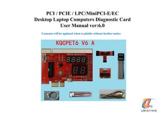
  • 1. PCI / PCIE / LPC/MiniPCI-E/EC Desktop Laptop Computers Diagnostic Card User Manual ver:6.0 LZM 2017/4/30 Contents will be updated when available without further notice T字板
  • 2. KQCPET6 V6 TypeA Master Diagnsotic Board and Accessories Supports PCI/PCI-E/ LPC/MiniPCI-E/ EC总线 EC wire USB cable(72cm)only need to be used when using the LPC or miniPCIe diagnosis. This cable needs to be connected before powering on the computer to run the diagnosis. LPC wire MiniPCI-E adapter T-Card(works on Desktop PC LPCs) Extension Cable (Connects the T- Card and miniPCIe Adapter to the Master Diagnostic Board P.5
  • 3. Simple Error LED Light Indicators video card Ram memory CPU CPU working status Bridges/HDD/USB/SATA -12V HDD/PCH RUN DISP RAM CPU IRDY FRAME RST CLK 12V AUX3V Main power/motherboard PCI slot detected mobo Motherboard signal Motherboard reset Motherboard clock signal Motherboard signal PSU/motherboard power • New simple faults LED lights, show the computer faulty areas, no need to use any digital codes interpretation, much easier than the LCD screen diagnostic cards. • Tech fact:Due to the periodical updates of the newer bios codes from the Bios and/or the computers manufacturers, only the Bios and/or the computer manufacturers have the most updated and complete list of the Bios codes. These LED lights work just as same as all other diagnostic cards on the market and needs to rely on the updated Bios codes, please use these LED codes as a quick reference. P.7
  • 4. LED lights corresponding parts check diagram
  • 5. KQCPET6 V6 all available LEDs P.8
  • 6. Indicator Light Signal Illustration Unstable Not stable If the computer motherboard is not stable, with potential faults or computer accessories parts are not fully compatible with the motherboard, this LED will be steady ON.(Only PCI and PCIe diagnosis comes with the Stability Test feature) Stable stable The computer is stable, no error. (Only PCI and PCIe diagnosis comes with the Stability Test feature) Ready Computer ready When this LED light ON(please take note all 3 dots must light up on the 4digital display, please check above picture), ok to reboot computer to do the stability test. If these Ready LED is not On, do not reboot computer for the Stability Test.(Only PCI、 PCIE connections come with Stability Test feature) -12V Power When the test card installing on the standard PCI slot , this LED will be steady ON otherwise, there is no such voltage from PSU or the motherboard is short. When using LPC、PCIE、MINIPCIE、EC、USB connections to test the computer, this LED need not to be On. HDD/PCH HDD / Bridges Hard Drive / Bridges (North or South) / SATA / USB modules self test failed RUN CPU RUN status Shows the CPU been running, as soon as CPU been initialized and run, this LED will light even though the CPU stopped working now, this LED will remain ON. To check on this LED, remove the CPU, power on the motherboard, if this LED still remains ON, the LED need to be checked for fault. DISP Video card / mobo GPU Video card / integrated motherboard GPU self test failed RAM Memory / mobo RAM RAM / motherboard memory module or power fault CPU CPU CPU / motherboard CPU coprocessor module or peripheral path self test failed IRDY Major device is ready Improved IRDY LED light, unique LED light when using the PCI slot, this LED lights ON when there is IRDY signal, works the same way as the CLK signal . This LED is absent when using the LPC、PCIE、MINIPCIE、EC connections. FRAME Frame period Improved FRAME LED light, it lights ON when there is frame cycle signals, works the same way as the CLK LED. RST Reset This LED flashes very quickly for about half a second when using the test card on the PCI slot during the power ON or pressing the Reset button on the computer. It remains ON if the reset wire connects to the wrong other pins on the motherboard or the motherboard reset circuitry is faulty. When using the LPC connection to test the computer, this LED may not light at all, please focus on the digital diagnostic codes. Only connecting with PCI or PCIe, this LED shows the motherboard reset activity. CLK Main Bus Clock This LED lights when there is CLK clock pulse signal. This LED may flash quickly enough so that it looks like never light at all. 12V Power This LED should remain steady ON when the test card is installed on the computer PCI slot , otherwise, there is no such voltage from the PSU or the motherboard is shorted. When using the LPC、PCIE、MINIPCIE connections, this 12v LED should remain OFF. AUX3V Power This LED is the unique 3.3v indicator on PCI、PCIE slots, should remain ON when the motherboard is powered ON. A few motherboards with built in PCI slots may not have this voltage. LPC connection does not have this voltage, so this LED will remain OFF. Open codes Open Code indicator Except code ‘no’, when this LED flash ON and OFF, the codes are the 2digit Qiguan open codes. If this LED remains OFF, the codes are Bios Code. On TypeB cards, this LED steady ON indicates the USB codes. KQCPET6 V6 LED Light Descriptions P.9
  • 7. PCI/PCIE/LPC/MiniPCI-E/EC Diagnostic Card (TypeA frontview) PCIE connector BIOS Code and Qiguan 2digit Open code display 2digit code check switch PCI connector EC wire 5pins connector Extension cable socket (connects the master card with T-Card or MiniPCIe Adapter Card) USB power connector(need to connect to USB for power when using LPC or MiniPCIE connections -12V 1HDD/PCH RUN DISP L RAM E CPU D IRDY FRAME L RST i CLK g 12V h AUX3V t Qiguan 4digit code display P.10
  • 8. Super IC Chips PCI/PCIE/LPC/MiniPCI-E/EC Diagnostic Card (Master Card back side) PCI connector 反面 PCIE connector P.11
  • 9.  When there is PCI and PCIe connectors on the same motherboard, please use the PCI slot.  When there is only PCI-E slot, please install the diagnostic card PCIe connector to the motherboard PCI-E X1/X4/X8/X16 connector.  Important:Never connect the PCIe connector to the motherboard non PCIe (PCI or AGP slots), this may short the diagnostic card and/or motherboard when the power is ON. P.12 Precaution for the Diagnostic Card PCI/PCI-E 1X Connection Correct Wrong
  • 10. Diagnostic Card and Motherboard PCI-Express x1  When there are different PCIe connectors available on the motherboard, please install the diagnostic card on the PCI-Express x1、 x4、x8、x16 slots,(please pay attention that some motherboards only x1 slot get the diagnostic codes.) P.13 Correct Correct
  • 11. Diagnostic Card and Motherboard PCI-E X4/X8/X16  When using the motherboard PCI-E connections, we may use the PCI- Express x4/x8/x16 slots, please pay attention that some motherboard only PCI-E x1 slot provides the diagnostic codes. The following pictures show the correction installation of the diagnostic card on the PCI-E X4/X8/X16 connectors. P.14 The correct installation of the diagnostic card on the PCI-E X16 connector
  • 12. The Wrong Installation of the Diagnostic Card to the Motherboard PCI-E x4/x8/x16 Connectors  When using the PC motherboard PCI-Express x4、x8、x16 connections, please watch not to install the diagnostic card incorrectly. Installing the diagnostic card wrong to the PCIe connectors will cause the shorts when powering ON. The following pictures show the wrong installations. P.15
  • 13. • When installing the diagnostic card to the computer PCI or PCIe connectors, the digital codes display units will auto adjust the orientation of the digital display. • A nice user friendly design. Orientation Auto-Adjustable Digital Codes Display Unit P.16
  • 14. LPC Diagnosis and the Motherboard LPC-Debug Connector  T-Card uses of the T type LPC adapter that connects to the large master diagnostic card KQCPET6 V6 first then connecting the T-Card to the motherboard to make the auto LPC diagnosis possible and more user friendly. Uses this T-Card on the motherboard that comes with the LPC-Debug connector. Please install the diagnostic card corresponding Large or Small LPC connector(as shown in the following right picture)to the motherboard ‘DEBUG_PORT’( Please take note that the different motherboards could have named the LPC debug ports differently). P.17 Large LPC Small LPC Works on the motherboards 2x5 pins layout LPC debug ports
  • 15. LPC Diagnosis and the Motherboard LPC-DEBUG Connector  In order to use the diagnostic kit on the motherboards with the LPC-Debug connectors, please install the diagnostic card LPC connector ( please select either large or small LPC pins connector on the T-Card) to the motherboard DEBUG_PORT. Before powering ON, please connect the USB power cable (the smaller micro USB connects to the master diagnostic card, the large USB connect to the motherboard standard USB port), then connect the T-card to the diagnostic card master board using the included extension cable (please see the following picture). Next powers ON the motherboard to wait for the final codes that stop changing. P.18
  • 16. The advantages of using the USB for supplying power to the diagnostic card • 1. USB ports come with the standard 5v power supply, easy to use; • 2. not rely on the motherboard LPC 3.3v for the power, can still diagnose the motherboard when the LPC power is faulty; • 3. reduces the burden to the LPC connector and thus help to maintain accurate diagnosis result; • 4. the LPC port may have the drop on the voltage due to several facrtors, using USB can help to supply the stable power for accurate diagnosis; • 5. helps to prevent the LPC power from overloading and causing the shorts; • 6. no need to add extra power components to the motherboard. More power components rise the opportunity of damage and shorts to the diagnostic equipments; • 7. These are just some advantages, more advantages of using USB for power but will not be listed here.
  • 17. USB Cable Use this cable for the USB diagnosis feature on the KQCPET6 V6 TypeB diagnostic card. This cable should be connected to the diagnostic card master board MICRO USB connector to diagnose desktop and laptop computers. When using the diagnostic card on the motherboard LPC connector or MINIPCIE, the USB cable is for getting the electrical power purpose only. To help the motherboard sees the diagnostic card, we need to get the power to the diagnostic card in advanced. So we need to connect the USB cable one end to the diagnostic card and the other end to the same computer USB port before powering on the computer to run the diagnosis. (using the USB power sources other than the same computer motherboard USB port may cause the diagnostic card not working). (the USB cable is only needed for LPC and MINIPCIE diagnosis) Each set of the diagnostic kit comes with an USB cable, smart phones MicroUSB cable is a compatible substitute. The actual USB cable includes with the diagnostic card may look slightly different than the one in this picture. P.20
  • 18. Extension Cable • The extension cable is used to connect the accessory parts such as the T-card and MINIPCIe adapter to the diagnostic card Master Board • When testing the desktop PC using the LPC method or testing the laptops using the MINIPCIe connector, uses of this extension cable helps to make the diagnosis much easier and convenient, just like adding the external display that allow viewing of the diagnosis codes more easily. P.21
  • 19. LPC Universal Adapter (T-Card) P.22  This T-card comes with 3 different sizes and specs LPC connectors to work on the different motherboards LPC Debug ports.  The small white triangle marks (please see the spots where the yellow arrows pointing to in the following pictures) shows the ‘pin 1’ position which needs to be aligned with the same pin 1 of the LPC port on the motherboard. Does not matter using the front side or the rear side pin1 of the T- Card, just make sure the pin 1s are aligned and matching. Try installing the T- card to the motherboard LPC port on each side and see which side gets the different codes running on the master test board.  When using the LPC diagnosis, select the large LPC pin connector or small LPC pin connector on the T- card first, then install this selected LPC connector to the same pin 1 on the motherboard LPC Debug port. This method applies to all different brand name computers and motherboards.  LPC(Large and small pins connector)comes with the complete protection design. If the motherboard LPC Debug ports come with over 12pins connection or more, no need to align the pin 1 method as described above, just install the LPC connector to the motherboard LPC Debug port with different pins combination until the different codes are running on the diagnostic card unit.  To use this LPC universal adapter card (T-card), please use the included extension cable to connect the card to the diagnostic card master board, then connect the included USB cable for power (must use the same computer motherboard USB port, not the other USB power sources such as the smartphone power adapter USB power connector to power the diagnostic card).  After all, if still not able to get the diagnostic codes running, please contact your seller for the helps and to see if any upgrade is needed. L a r g e L P C L a r g e L P C S m a l l L P C S m a l l L P C Works on the motherboards with 2x5 pins layout LPC debug port Works on the motherboards with 2x5 pins layout LPC debug port
  • 20. LPC Fully Automatic Feature • ‘Fully Automatic' means that the diagnostic card can automatically recognize and see the different motherboard LPC ports. The advantages are: • 1.one card fits all, no need any other converters or jumpers a、compatible to the known converted types LPC and the newly invented types LPC connectors. In the case that the LPC debug port is not compatible, need not to buy the extra diagnostic card or another LPC converter card, just need to do the upgrade on the current diagnostic card. The IC chips hardware upgrade and the shipping costs are extra. b、no risk of the extended damages to the computer due to the incorrect connecting of the adapter or jumpers. 2. No need to pay attention to the brand name or model of the motherboard during the diagnosis. 3. install the LPC connectors to the motherboard LPC debug port the right way or completely using the other turn around way, the diagnostic card will still work normally. If there are Pin1 marks on the both side of the LPC adapter card, try freely by connecting the LPC adapter to the motherboard LPC debug port without any fix pin orientation. Just try different ways, different pins connections till there are different diagnostic codes running on the diagnostic card. P.23
  • 21. Installing the LPC Connector on the Motherboard • On the LPC universal adapter card(T-Card), there is a small white triangle mark highlighting the pin1 on both Large and Small LPC pins connectors. Look for the same pin1 on the motherboard LPC Debug connector. Align pin1s and install the T-Cards to the motherboard LPC Debug Connector (please see the following pictures for the correct installation.) • Just pay attention on the pin1 alignments, ignore the missing pin on the motherboard LPC debug port. • If installing the LPC connector incorrectly, the diagnostic card will not work, but will not burn or causing damages. Try again until installing the LPC adapter correctly on the motherboard LPC debug port. Correct wrong P.24
  • 22. The following installations are all correct There are situations that the motherboard LPC Debug ports may come with more or fewer pins than the Large and Small LPC pins connectors. Just install and do the diagnosis. P.25
  • 23. The LPC Debug Ports on the Motherboards (part 1) P.26
  • 24. • 1、Until the time this user manual is being finalized, there are several new LPC connectors being found. We will keep on looking for the new LPC connector types. In the case that there is any new LPC connector not being supported, please contact seller supports for the upgrade info. IC chip hardware upgrade and the shipping costs are extra. • 2、Installing the LPC improperly or wrongly will not causing any damages, just causing the diagnostic card not getting the error codes. If not able to locate the pin1 on the motherboard LPC debug port, please try the different LPC pins connections until getting the different diagnostic codes or please contact seller support for more assistance. The LPC Debug Ports on the Motherboards (part 2) P.27
  • 25. Upgrade When there are“LPC、DEBUG、TPM”etc connectors on the motherboard but not getting the changing diagnostic codes, please contact the support for upgrade. The IC chips hardware upgrade and shipping postages are extra.. Qiguan reserves the rights of upgrades. P.28
  • 26. Diagnostic Card – RUN LED Light • RUN LED light depends on a very few components to work so comes with a very low error rate. It rely very little on the motherboard connector slot to provide the diagnostic LED codes, so even it is installed on the faulty slot and all other LEDs not getting the diagnostic result, this RUN LED may still work. Just stick to the theory that as soon as this LED flashes, the motherboard used to work. Please use this theory to help diagnose the following problems: 1. Part of the diagnostic card is faulty 2. The diagnostic card is not compatible with the motherboard 3. The connector that the diagnostic card being installed on is faulty 4. The diagnostic card has not installed properly on the motherboard. Or there is poor contacts due to the dirty/rusty diagnostic card pins or connector slot pins. 5. Motherboard is dead • 6. Motherboard is executing the other non-diagnosis related tasks. • As soon as the CPU works, this LED will be ON. If the CPU used to work once and stop now, this LED will remain ON • To check on if this LED is faulty, please remove the CPU, powers on the computer, if this LED still ON, the LED is faulty. P.29
  • 27. Diagnostic Card- CLK(Clock) Signal LED  This LED lights ON when there is Clock signal  Some motherboards will turn this LED OFF after the booting to the Windows. P.30
  • 28. Diagnostic Card-RST(Reset) Signal LED  When using the PCI slot, this LED reflects the PCI slot reset signal. This LED could take a fraction of the second to flash, most about half a second.  When using the PCIE slot, this LED reflects the PCIE express slot reset signal.  When using the motherboard LPC-DEBUG port, this LED could remain steady ON or OFF. Since LPC reset signal cannot represent the motherboard reset circuitry logic, we can ignore this LED when using the LPC diagnosis.  When using the miniPCIE slot, this LED reflects the miniPCIE slot reset signal, this LED flashes when there is reset activity. P.31 · ·
  • 29. Diagnostic Card–AUX3V LED  When the computer is connected to the main, no matter the computer is power On or OFF, this LED lights ON when the diagnostic card master board is installed on the motherboard PCI or PCIe slot.  If this AUX3V LED is dim on boot, please check the Bios settings if the energy saving option is enabled.  Motherboard LPC port does not have this AUX3V voltage, so this LED will remain OFF on LPC. P.32
  • 30. Diagnostic Card– HDD/PCH LED  HDD/PCH Steady ON indicates that the HDD, North Bridge, South Bridge, USB and SATA etc modules are faulty. P.33
  • 31. Diagnostic Card – DISP LED  DISP LED steady ON indicates that the video card is faulty or it driver is corrupted. P.34
  • 32. Diagnostic Card–RAM LED  RAM LED steady ON indicates that the RAM module did not pass the self test. P.35
  • 33. Diagnostic Card–CPU LED  CPU LED steady ON indicates that the CPU did not pass the self test. P.36
  • 34. Diagnostic Card–IRDY LED P.37  IRDY LED OFF indicates there is no IRDY signal(this IRDY signal only present on PCI interface)。
  • 35. Diagnostic Card–FRAME LED Improved FRAME LED, this LED flashes when there is cycling FRAME signal. P.38
  • 36. Open Diagnostic Code LED P.39 BIOS code / Qiguan 2digit open diagnosis code display unit TypeB: USB open diagnosis codes 1.This LED ON indicates above 2digits are USB open diagnosis codes. 2.This LED flashes to indicate the above 2digit codes are open diagnosis codes. 3.This LED OFF indicates the above 2digits are BIOS POST codes(When the above 2digit showing “no” and this LED also remains OFF, indicating there is no BIOS codes been detected.
  • 37. MINI PCI-E Adapter Card Extension cable socket • This adapter card needs to be installed on the laptop Mini PCI-E slot which must connect to the LPC bus to start the diagnosis. If there is no LPC bus connected to the Mini PCI-E slot, we need to use wires to connect the IO pins to get the diagnostic codes.(please see LPC fly wire for more info), not all laptop Mini PCI-E can get the diagnosis codes. • When using miniPCIe diagnosis and the Bios codes showing ‘no’, needs to connect the fly wire to the laptop motherboard to get the Bios diagnosis codes. • Correct connection:1.please install the MiniPCIE adapter card to the laptop motherboard WIFI MiniPCI connector and use a screw to anchor the adapter card. 2.Next is connecting the MINIPCIE adapter card to the motherboard using the included extension cable. 3.Connect the USB cable (one end to the same motherboard USB connector and the other end connects to the diagnostic card USB connector, powers on the computer to start the diagnosis, please see the following picture for more info., P.40 MiniPCIE adapter card and Diagnostic Card master board connection 7pins fly wire connection socket
  • 38. LPC Wire (Fly Wire) • KQCPET6 V6 diagnostic card allows the connection to the miniPCIe adapter card which supports the LPC diagnosis (please see the followings for more info about this LPC connector): • Most of time, laptops do not have the specific connector for this LPC connection directly. So need to use the LPC wire (also called fly wire) to connect the LPC connector on the miniPCIe adapter card to the laptop motherboard. • If the motherboard comes with PLCC32BIOS, we can use the LPC wire to connect the diagnostic card to the laptop motherboard LPC connector BIOS. Besides using the LPC Bios connection, we can also connect the diagnostic card to the laptop motherboard LPC connector IC chips. Some commonly seen LPC chips are PC97551, PC87541, PC87591,H8S/2149, W83L950D,TCPA etc. • The followings are some examples of the laptop IC chips LPC pins , more info please visit the IC chip data guides. • How to connect? Please use the included LPC wire plug to the MiniPCIE adapter card LPC wire socket, the other end of the LPC wire need to follow the instruction to be welded to the laptop motherboard LPC connector corresponding IC chip pins. The following picture shows the MiniPCIE part. This method is only recommended for the professional chipset level repair technicians, not for personal repairs! LPC Connector (Fly wire socket) Connect to the laptop motherboard LPC IC chip (must follow the LPC diagram to connect to the corresponding LPC pins) LPC wire socket connector P.42 Extensio n Cable Socket
  • 39. P.43
  • 40. EC Wire • This wire uses specifically on the laptop motherboards with the EC DEBUG port. • This wire connects the diagnostic card to the laptop EC connector. P.44 EC connector (5pins connector) 4pins laptop motherboard EC connector EC wire
  • 41. BIOS Diagnostic Codes P.41 • BIOS codes comes with 2digits. These 2digit Bios code descriptions were defined by the Bios manufacturers, also called the traditional diagnosis. • Use the diagnostic card on the PCI/PCI-E/MiniPCI-E/LPC connectors, we can see the each connector’s Bios code. But not all motherboards diagnosis get the Bios codes. • When this diagnostic card is installing on the above connectors, the Bios Code digits showing ”no ”and the small dots on the same 2digits keep flashing, this indicates that the current slot connector does not have the Bios codes AND no Qiguan open diagnosis codes as well. Please be advised to install the diagnostic card to the motherboard other connectors and do the diagnosis again. Also please look for the 4digit Qiguan codes for descriptions. P.45 BIOS Codes/ Qiguan 2digits open diagnosis code display unit TypeB card: USB open diagnosis codes
  • 42. Traditional Diagnosis Features • 1. Comes with the AUX3V、+12V、-12V Power LEDs and CLK、 RST、FRAME、IRDY、RUN signal LEDs. Capable of showing the blank screen motherboard repeated auto reset faults that leads to the No POST and dead machine. • 2.Completely eliminated the onboot random codes. No more difficulty in distinguishing between the machine startup initialization codes and the diagnostic error codes. • 3.Allows the checking of some important motherboard activities even when the CPU is not installed on the motherboard. • 4.Supports 80h、84h、300h ports simultaneously. • 5.Allows the diagnosis to be completed at one time without any interruption. Improved performance and stability. • 6.The diagnostic card with the best compatibility ever made. Capable of diagnosing all high-end and low-end motherboards. (Including Intel,AMD,VIA etc all series with servers motherboards), comes with very high diagnostic accuracy and the stability. P.46
  • 43. Qiguan 2digit Open Diagnosis Codes Features • These 2digits Diagnosis apply to the PCIe and MiniPCIe Slots • As shown in the following picture, when the small dots steady OFF/not flashing, the diagnosis codes will be the Bios Codes. • When the small dots flashing, the diagnosis codes will be the Qiguan 2digit open codes. • When showing “no”, small dots flashing, there is no Bios Code and no Qiguan open codes as well. • TypeB card when connect to the USB and no diagnostic codes coming from any other bus connector, the diagnostic card will show the USB open codes. P.47 BIOS Codes/ Qiguan 2digits open diagnosis code display unit TypeB card: USB open diagnosis codes
  • 44. How can the end user collect Qiguan 2digit open diagnosis codes? Please submit the following info to the Qiguan support. • Uses of the standard computer motherboard to collect the following info: a.take the picture of the motherboard model number. b.power off the PC and remove the RAM modules. c.install the diagnostic card to motherboard then power on the PC d.Take the photo of the codes on the diagnostic card(must showing in the photo that the RAM modules been removed) • Collect the open codes during the PC diagnostic process (before the repairs):a.take photo of the motherboard model number,b take record of the 2digit open codes ;c.install the diagnostic card to the other bus connector to test the motherboard or use other methods to repair the computers. After the repairs, if reaching the similar problem on the other computers, just need to check on the earlier recorded diagnosis codes, we can solve the computers with the similar symptoms quickly. When displaying ‘no’, the small dots on the digital display flashing, this motherboard does not have the open codes, please be advised to install the diagnostic card on the other PCIe connectors to do the diagnosis again. BIOS codes/ Qiguan 2digit open codes display unit P.48
  • 45. 2digit Qiguan Open Codes Demo Pictures P.49 Qiguan 2digit open code display unit.This time, we can see the codes 8E on a motherboard without RAMs. No RAM installed
  • 46. Qiguan 4digit Diagnostic Codes Assistance to the Novice and the Handy Tools to the Professional • 1.Consistently checking if the diagnostic card is error-free. Generates the codes to warn user if the diagnostic card is faulty. Avoids inaccurate diagnosis. • 2.CPU affects the most traditional diagnostic cards working condition. Qiguan diagnosis helps to find out the factors that causing the non functional traditional diagnosis. Helps to restore the traditional diagnosis by fixing the errors. • 3.Qiguan diagnosis does not rely on the BIOS version info. The Qiguan diagnostic codes are clear, complete and accurate. Complete checkings on the BIOS POST Codes properties. Reduces the traditional diagnostic card faults. • 4.Technology breakthrough the traditional diagnostic card limitation. Besides allowing the PCI、PCIE、LPC、MiniPCIE advanced interface diagnosis connections, it also creates many sections to help improve the diagnosis accuracy and reliability. P.50
  • 47. Qiguan 4digit Diagnostic Codes 4digit Qiguan Codes Display Unit • Qiguan Diagnostic Codes are 4digits Hexadecimal codes. Designed, Defined and Developed by Qiguan. It is different from the BIOS codes. Each of the Qiguan Diagnostic Codes comes with the corresponding definitions. There are some 4digit codes defined differently on the diagnostic card KQCPET6 V6 than the KQCPET6-H V1/V2 cards. If have any question, please contact Qiguan support. • The diagnostic card will show the corresponding 4digit Qiguan codes when being used on the different interface connectors. • Qiguan diagnostic codes allow the user interactive checking option.---- The smart phone App. Use the smart phones to scan the QR code or download the APP files for the installation, allows quick check of the codes anytime anywhere. P.51
  • 48. Diagnostic card– UnstableStableReady LEDs • Qiguan diagnostic cards unique stability test feature is indicated by 3 parts, just need to follow the stability test procedure in the next page to complete the test. The 3 parts are UnstableStableReady LEDs(the last part ‘Ready’will be indicated by the 3 small dots as shown in the following picture(so total 5 dot LEDs to check).
  • 50. Stability Test Features • 1. Stability test results will be given as ‘Unstable’ and ‘Stable’ 2 LEDs, clear and straight. • 2. Independent Stability Test can be done by the guide of the flowchart or the 4digit Qiguan codes. Can be done as needed. • 3.Besides testing the working computers stability, also test if the faulty computers contains the fixed faults or variable erros. Eg. Semi faulty computers that sometimes working, sometimes not with hidden hardware errors. This test helps to find out the faults and eliminate the errors. • 5.This feature can be used to help selecting the computer or the computer parts. It can help the users in buying the computers or purchasing the quality accessories parts such as RAM, HDD, keyboard…etc) as well as the peripherals such as UPS, printer, USB devices and ATM machines…etc. Also helps the computer vendors to set the prices correctly for the stable computers. P.62
  • 51. The Diagnostic Code “no” The Bios diagnostic codes showing “no”indicates that there is no Bios POST code been received. Same as the initialization codes of the diagnostic card. P.63
  • 52. What to do with this Bios Code ‘no’ when the diagnostic card is installing on the PCI slot? 1. Showing POST code ‘no’when the diagnostic card is not properly installed on the motherboard. solution:①Clean the diagnostic card pins by using a paper rubber ②There is dust, rust or oxidations on the motherboard slot. Please clean the slots and reseat the diagnostic card a couple more times. Check the slot pins for any loose, bent or broken pins. All these situations will cause the improper contacts so that the diagnostic card will not be able to perform the diagnosis or giving an inaccurate diagnostic results. If there is poor or no contact of the pins, the diagnostic card will show the following symptoms: blank display no diagnosis display, no Bios Code / wrong code, LEDs remain OFF, normal Qiguan codes will be reported as none . 2. When CPU never worked, the codes will show ‘no' and the RUN LED remains OFF Solution:Motherboard did not initialized, check if CPU is faulty, check CPU jumpers and settings, check PSU voltages, motherboard CMOs battery. 3. Some empty motherboards without RAM, RAM failed the self test or RAM incompatibility, the Bios codes showing ‘no’. Solution: Clean the RAM pins with a paper rubber, clean the RAM slots, reseat the RAM properly. Observe if the diagnostic codes are getting the new codes. P.64
  • 53. 4. The motherboard Bios is faulty Solution:Refresh / reprogram the BIOS. 5.Computer works normally, still showing ‘no’; Solution:If still showing ‘no' after checking all pins contacts are good, the motherboard slot is not getting the BIOS codes, please be advised to use the diagnostic card on the other motherboard slots (LPC/PCI), or on the other motherboards, as soon as any other slot or motherboard gets the different codes than ‘no’, the diagnostic card is a working unit. 6. Qiguan codes(Only applies to the Qiguan diagnostic card with 4digit Qiguan diagnosis) already indicated those factors that causing Bios codes ‘no’. Solution:Correct the errors reported by the Qiguan diagnosis codes. P.65
  • 54. What to do when the codes showing ‘no' on LPC connection diagnosis? • 1.First check on the motherboard LPC connector to make sure it is marked any of the followings: LPC_DEBUG、LPC、DEBUG、LPC1、DEBUG PORT、JLPC、LPC_CON、LPC-DEBUG、 LPC/TPM1、JTPM1、TPMS1、TPM etc. dual rows of the LPC pins; • 2.Next look for the ‘pin1’ on the motherboard LPC debug port. • 3.Double check the above 2 checks are correct, then select either large or small LPC connector and align the pin 1 to install the LPC connector on the motherboard LPC debug port. • 4.check if the USB power cable is in advance connected to the diagnostic card which will be installed on the motherboard LPC debug port. • 5. Then powers on the computer, if still showing ”no”, motherboard LPC pins could have the oxidations or poor contacts, just need to power off and reseat the LPC connectors a few more times to help get rids of the oxidations and rust for better pins contacts. • 6.CPU never worked and showing ‘no’and the diagnostic card RUN LED remains OFF.; Solution:First check if there is any CPU open circuitry. Check if the CPU is getting the power and heating up after power on. P.66
  • 55. • 7.Some empty motherboards without the RAM installed or the RAM failed the self test / RAM incompatibility will show the code ‘no’, please try use the paper rubber to clean the RAM pins, clean the RAM slots, reseat the RAMs and check if there is any new diagnostic codes. • 8.motherboard BIOS faulty solution:refresh or reprogram the Bios and try again. If not familiar with the motherboard BIOS refresh, please do not do this. • 9. Computer works normally, still showing ‘no’; Solution:If still showing ‘no' after checking all pins contacts are good, the motherboard slot is not getting the BIOS codes, please be advised to use the diagnostic card on the other motherboard slots (LPC/PCI), or on the other motherboards, as soon as any other slot or motherboard gets the different codes than ‘no’, the diagnostic card is a working unit. • 10. Qiguan codes(Only applies to the Qiguan diagnostic card with 4digit Qiguan diagnosis)already indicated those factors that causing Bios codes ‘no’. Solution:Correct the errors reported by the Qiguan diagnosis codes. P.67
  • 56. What to do when the codes showing ‘no' on PCIE connection diagnosis? • The 2digit codes showing ‘no’on the PCIe connection diagnosis indicates that the diagnostic card is not getting the BIOS Code and not getting the Qiguan 2digit open codes as well. • 1.on the motherboards with both PCI and PCIe connectors, please use the PCI as priority, this is because the motherboard manufacturers could have designed one of these connectors to outputting the BIOS codes, while the other connector will not have the Bios codes. • 2.When the motherboard does not come with PCI but PCIE slot, the diagnostic codes showing ‘no’, the followings are the 2 possibilities. • a. there is other BIOS diagnostic port such as LPC connector on the motherboard. Please use the LPC diagram guide in this manual to help checking if there is LPC debug port on the motherboard, if so, please use the LPC diagnosis instead. • b. If there is no other LPC debug port but only the PCIe slot, the motherboard has no Bios codes sent to its PCIe connector, we can do the followings: • ①CPU never worked with the bios codes ‘no' and the RUN LED remains OFF. Solution:First check if there is any CPU open circuitry. Check if the CPU is getting the power and heating up after power on. P.68
  • 57. • ②. Some empty motherboards without the RAM installed or the RAM failed the self test / RAM incompatibility will show the code ‘no’, please try use the paper rubber to clean the RAM pins, clean the RAM slots, reseat the RAMs and check if there is any new diagnostic codes. • ③. motherboard BIOS faulty solution:refresh or reprogram the Bios and try again. If not familiar with the motherboard BIOS refresh, please do not do this. • ④. Computer works normally, still showing ‘no’; Solution:If still showing ‘no' after checking all pins contacts are good, the motherboard slot is not getting the BIOS codes, please be advised to use the diagnostic card on the other motherboard slots (LPC/PCI), or on the other motherboards, as soon as any other slot or motherboard gets the different codes than ‘no’, the diagnostic card is a working unit. • ⑤ .Qiguan codes(Only applies to the Qiguan diagnostic card with 4digit Qiguan diagnosis) already indicated those factors that causing Bios codes ‘no’. Solution:Correct the errors reported by the Qiguan diagnosis codes. P.69
  • 58. Q &A • 1、There are so many diagnosis connectors, how to assure the diagnostic accuracy? • Answer:Diagnostic card can automatically identify each different connector and generate the diagnostic codes, the diagnosis results will not be affected by the numbers of different diagnosis connectors. • 2、TypeA diagnostic card uses USB for power purpose only, if need to get the USB open codes on Type A cards, what can be done? • Answer:Only TypeB diagnostic card comes with this feature, please use the TypeB card for this purpose. P.70
  • 59. Q & A • 3、the diagnostic card cannot find out the problem on my computer, what to do next? • Answer:there are so many different types of computers with different daily updated motherboards designs on the market. No single motherboard diagnostic card can diagnosis all computers and find all the problems. This diagnostic card just like all others, but we always do our best works to make our diagnostic cards superior than any others and also to works on more computers than others. • Thanks for your trust and supports on Qiguan! P.71
  • 60.
  • 61. UEFI BIOS POST CODE Code Explanation A3 Activated all currently connected IDE devices. 92 PCI Bus initialization is started. A4 SCSI initialization is started. 93 PCI Bus hot plug initialization. A5 Issue reset during SCSI initialization process. 94 PCI Bus enumeration for detecting how many resources are requested. A6 Detect and install all currently connected SCSI devices. 95 Check PCI device requested resources. A7 Activated all currently connected SCSI devices. 96 Assign PCI device resources. A8 Verify password if needed. 97 Console Output devices connect (ex. Monitor is lighted). A9 BIOS Setup is started. 98 Console input devices connect (ex. PS2/USB keyboard/mouse are activated). AA Reserved. 99 Super IO initialization. Ab Wait user command in BIOS Setup. 9A USB initialization is started. AC Reserved. 9b Issue reset during USB initialization process. Ad Issue Ready To Boot event for OS Boot. 9C Detect and install all currently connected USB devices. AE Boot to Legacy OS. 9d Activated all currently connected USB devices. AF Exit Boot Services. 9E~9F Reserved. B0 Runtime AP installation begins. A0 IDE initialization is started. B1 Runtime AP installation ends. A1 Issue reset during IDE initialization process. B2 Legacy Option ROM initialization. A2 Detect and install all currently connected IDE devices. B3 System reset if needed. P.1
  • 62. EFI BIOS POST CODE General Power 95 Check PCIdevice requested resources. code Meaning 96 Assign PCI device resources. 10 PEI Core is started. 97 Console Output devices connect (ex. Monitor is lighted). 11 Pre-memory CPU initialization is started. 98 Console input devices connect(ex. PS2/USB keyboard/mouse are activated). 12~14 Reserved. 99 Super IO initialization. 15 Pre-memory North-Bridgeinitialization is started. 9A USB initialization is started. 16~18 Reserved. 9b Issue reset during USB initialization process. 19 Pre-memory South-Bridge initialization is started. 9C Detect and install all currentlyconnected USB devices. 1A~2A Reserved. 9d Activated all currentlyconnected USB devices. 2b~2F Memory initialization. 9E~9F Reserved. 31 Memory installed. A0 IDE initialization is started. 32~36 CPU PEI initialization. A1 Issue reset during IDE initialization process. 37~3A IOH PEI initialization. A2 Detect and install all currentlyconnected IDE devices. 3b~3E PCH PEI initialization. A3 Activated all currentlyconnected IDE devices. 3F~4F Reserved. A4 SCSI initialization is started. 60 DXE Core is started. A5 Issue reset during SCSI initialization process. 61 NVRAM initialization. A6 Detect and install all currentlyconnected SCSI devices. 62 Installation of the PCH runtime services. A7 Activated all currentlyconnected SCSI devices. 63~67 CPU DXE initialization is started. A8 Verify password if needed. 68 PCI host bridge initialization is started. A9 BIOS Setup is started. 69 IOH DXE initialization. AA Reserved. 6A IOH SMM initialization. Ab Wait user command in BIOS Setup. 6b~6F Reserved. AC Reserved. 70 PCH DXE initialization. Ad Issue ReadyTo Boot event for OS Boot. 71 PCH SMM initialization. AE Boot to Legacy OS. 72 PCH devicesinitialization. AF Exit Boot Services. 73~77 PCH DXE initialization (PCH module specific). B0 Runtime AP installation begins. 78 ACPI Core initialization. B1 Runtime AP installation ends. 79 CSM initialization is started. B2 Legacy Option ROM initialization. 7A~7F Reserved for AMI use. B3 System reset if needed. 80~8F Reserved for OEM use (OEM DXE initialization codes). B4 USB device hot plug-in. 90 Phase transfer to BDS (Boot DeviceSelection) from DXE. B5 PCI device hot plug. 91 Issue event to connect drivers. B6 Clean-up of NVRAM. 92 PCI Bus initialization is started. B7 ReconfigureNVRAM settings. 93 PCI Bus hot plug initialization. B8~BF Reserved. 94 PCI Bus enumeration for detecting how many resources are requested. C0~CF Reserved. P.2
  • 63. P.3 EFI BIOS POST Code S3 wake ERROR CODE Meaning CODE meaning E0 S3 Resume is stared (called from DXE IPL). 50~55 Memory initialization error occurs. E1 Fill boot script data for S3 resume. 56 Invalid CPU type or speed. E2 Initializes VGA for S3 resume. 57 CPU mismatch. E3 OS S3 wake vector call. 58 CPU self test failed or possible CPU cache error. 59 CPU micro-code is not found or micro-code update is failed. recovery 5A Internal CPU error. CODE Meaming 5b Reset PPI is failed. F0 Recovery mode will be triggered due to invaild firmware volume detection. 5C~5F Reserved. F1 Recovery mode will be triggered by user decision. D0 CPU initialization error. F2 Recovery is started. D1 IOH initialization error. F3 Recovery firmware image is found. D2 PCH initialization error. F4 Recovery firmware image is loaded. D3 Some of the Architectural Protocols are not available. F5~F7 Reserved for future AMI progress codes. D4 PCI resource allocation error. Out of Resources. D5 No Space for Legacy Option ROM initialization. D6 No Console Output Devices are found. D7 No Console Input Devices are found. D8 It is an invaild password. D9~DA Can't load Boot Option. Db Flash update is failed. DC Reset protocol is failed. DE~DF Reserved. E8 S3 resume is failed. E9 S3 Resume PPI is not found. EA S3 Resume Boot Script is invaild. EB S3 OS Wake call is failed. EC~EF Reserved. F8 Recovery PPI is invaild. F9 Recovery capsule is not found. FA Invalid recovery capsule. Fb~FF Reserved.
  • 64. CODE meaning Explanation C0 Turn off chipset cache Close OEM manufacturers to design the Cache Controller CPU status (1 FLAGS) test 1 Microprocessor Test 1 Test CPU following states:. Carry, zero, sign, overflow BIOS setting each state and tested. 2 Microprocessor Test 2 Read / write / verify all of the CPU cache, SS, SP, and BP buffer containing 00 FF and the data type do this test. 3 Initialization Chipset Close NMI, PIE, AIE, UEI, SQWV. Close video, parity checking, DMA. Reset point arithmetic (math coprpcessor).Clear has paging cache, CMOS shutdown octet initialization Timer 0, 1, 2, including 4 Memory Test RAM test can be normal Refreshed, ensure Refresh memory function can work. 5 Initialize keyboard and clear the screen Initialization Keyboard controller and clear screen.( IOR*. IOW*. RESET . Clock SA2 ) 6 Reserved Reserved 7 Test CMOS interface and battery status Test CMOS interface and battery status Detecting whether the battery in good condition. bE Chipset default value is initialized The chipset buffer to boot (Power On) default so easy to enter the boot state. C1 Memory presence test OEM specific, test the size of on-board memory OEM specific, early shadow enable for fast boot;memory self- P.4 AWARD BIOS POST CODE
  • 65. AWARD BIOS POST CODE CODE meaning Explanation 0A Set up interrupt vector ta ble nitialize first 120 interrupt vectors. The interrupt address 00h to 1Fh address set to be consistent with the INT-TBL. 0b Test CMOS RAM checksu m CMOS RAM checksum test, if an error or insert key is pressed, the preset load. 0C Initialization keyboard Detects the presence of Keyboard in KBC port and Set NUM _LOCK Status 0d Initialize video interface Detect CPU clock, read CMOS location 14h to find the type o f video in use, detect and initialize video adapter 0E Test video memory Write sign-on message to screen, setup shadow RAM 0F Test DMA controller 0 BIOS checksum test, keyboard detect and initialization. 10 Test DMA controller 1 11 Test DMA page registers Test DMA page registers 12~13 Reserved 14 Test timer counter 2 Test 8254 timer counter 2 15 Test 8259-1 mask bits Test 8259-1 mask interrupts is normal.. 16 Test 8259-2 mask bits Test 8259-2 mask interrupts is normal.. 17 Test stuck 8259 interrupt bits Test stuck 8259 interrupt bits; Test stuck key. 18 Test 8259 interrupt functi onality Interrupt and checks the interrupt operation is normal. P.5
  • 66. CODE meaning Explanation POST DEBUG CODE (practical AWARD 6.0version) C0 Turn off chipset cache C1 Memory presence test; OEM specific, test the size of on- board memory C3 memory self-check C5 Early shadow; OEM specific, early shadow enable for fast boot;memory self-check 08 Test special keyboard controller for Winbond 977 series S uper I/O chips; Enable keyboard interface 29 Initialization Graphics 2d Display system information 52 Test all memory (clear all extended memory to 0) FF Boot loader (INT 19h) P.7 P.6 AWARD BIOS POST CODE
  • 67. Code Meaning Instructions POST DEBUG CODE (PHOENIX BIOS 6.0) 06 Initialize system hardware 08 Initialize chipset 16 BIOS ROM checksum 28 Test for memory( Autosize DRAM) 29 Initialize POST Memory Manager 2A Clear 512 KB base RAM 4A Initialize all video adapters in system 50 Display CPU type and speed F6 Clear Huge Segment F7 POST done - prepare to boot operating system P.7 PHOENIX BIOS POST CODE
  • 68. AWARD BIOS POST CODE CODE meaning Explanation 1B~1E Reserved 1F Set EISA mode Set EISA mode; If the EISA memory checksum is good then EISA is initi alized. If it's not good then ISA tests and clear EISA mode flag 20 Enable slot 0 Enable slot 0(System Board). 21~2F Enable slots 1- 15 Initialization slots 1 to 15. 30 Test base and ex tended memory Size base and extended memory; Size the base memory from 256K to 640K and the extended memory above 1MB 31 Test base and ex tended memory Test the base memory from 256K to 640K and the extended memory above 1MB using various bit patterns注意: EISA mode does not perform this test, under ISA mode you can press the ESC key to skip this test. 32 Test EISA extend ed memory If EISA mode set, then tested on a memory Slots Note: This test mode will be omitted under the ISA, EISA mode, press the ESC key to skip this test. 33~3b Reserved 3C Setup enabled 3d Initialization and install the mouse Initialize and install mouse if present. P.8
  • 69. Code Meaning Instructions BOOT BLOCK DEBUG CODE Before d0 Save power-on CPUID value in scratch CMOS. d0 Power CPU and chipset initialization Go to flat mode with 4GB limit and GA20 enabled. Verify the bootblock checksum. Early chipset initialization is done. Early super I/O initialization is done including RTC and keyboard controller. NMI is disabled. d1 Power-SIO initialization Early chipset initialization is done. Early super I/O initialization is done including RTC and keyboard controller. NMI is disabled. Including RTC and keyboard controller, serial, parallel, floppy controller initialization. d2 Early super I/O and chipset initialization Open the cache, examine BootBlock checksum; open RTC; SIO initialization of Hareware Monitor, north and south bridge and OEM north and south bridge. d3 Early BootBlock initialization If memory sizing module not executed, start memory refresh and do memory sizing in Bootblock code. Do additional chipset initialization. Re-enable CACHE. Verify that flat mode is enabled. d4 Test memory Test base 512KB memory. Adjust policies and cache first 8MB. Set stack. Bootblock code is copied from ROM to lower system P.9 AMI BIOS POST CODE
  • 70. Code Meaning Explanation INT13,INT0E,INT1E E9 Set up floppy controller and data. Attempt to read from floppy. EA Enable ATAPI hardware. Attempt to read from ARMD and ATAPI CDROM. EB Disable ATAPI hardware. Jump back to checkpoint E9. EF Read error occurred on media. Jump back to checkpoint EB. F0 Search for pre-defined recovery “AMIBOOT. ROM” file name in root directory. F1 Recovery file not found “AMIBOOT. ROM” F2 Start reading FAT table and analyze FAT to find the clusters occupied by the recovery file. F3 Start reading the recovery file cluster by cluster. F5 Disable L1 cache. FA Check the validity of the recovery file configuration to the current configuration of the flash part. Fb Make flash write enabled through chipset and OEM specific method. Detect proper flash part. Verify that the found flash part size equals the recovery file AMI BIOS POST CODE P.10
  • 71. Code meaning Explanation Fd Program the flash part. FF The flash has been updated successfully. Make flash write disabled. POST DEBUG CODE (Practical AMI 8.0) 03 Start Post Disable NMI, Parity, video for EGA, and DMA controllers. Initialize BIOS, POST, Runtime data area. Also initialize BIOS modules on POST entry and GPNV area. Initialized CMOS as mentioned in the Kernel Variable "wCMOSFlags." 04 CMOS initialization Check CMOS diagnostic byte to determine if battery power is OK and CMOS checksum is OK. Verify CMOS checksum manually by reading storage area. If the CMOS checksum is bad, update CMOS with power-on default values and clear passwords. Initialize status register A. Initializes data variables that are based on CMOS setup questions. Initializes both the 8259 compatible PICs in the system 05 Initializes the interrupt controlling hardware Initializes the interrupt controlling hardware (generally PIC) and interrupt vector table. Uncompressed POST code;ROM BIOS checksum tested; AMI BIOS POST CODE P.11
  • 72. Code meaning Explanation 2E Initializes all the output devices. 31 Allocate memory for ADM module and uncompress it Allocate memory for ADM module and uncompress it. Give control to ADM module for initialization. Initialize language and font modules for ADM. Activate ADM module. 33 Initializes the silent boot module Initializes the silent boot module. Set the window for displaying text information. 37 Display BIOS Information Displaying sign-on message, CPU information, setup key message, and any OEM specific information. 38 Mid-POST device initialization. Initializes different devices through DIM. See DIM Code Checkpoints section of document for more information. 39 Initializes DMAC-1 & DMAC-2. 3A RTC detection Initialize RTC date/time. 3b Detection of system memory Test for total memory installed in the system. Also, Check for DEL or ESC keys to limit memory test. Display total memory in the system.。 3C Mid POST initialization of chipset registers. Initialization SATA, HAD and BGA OEM POST mid-initialized. In the mid-POST, Detect different devices (Parallel ports, serial ports, and coprocessor in CPU, … etc.) successfully AMI BIOS POST CODE P.12
  • 73. Code Meaning Instructions 8d Build ACPI tables (if ACPI is supported) Build ACPI tables (if ACPI is supported) 8E Configuring Peripherals Program the peripheral parameters. Enable/Disable NMI as selected 90 Initialization Late SMI Late POST initialization of system management interrupt. A0 Check boot password if installed. If the user has set a password before, you will be prompted to enter the password authentication information. A1 Clean-up work needed before booting to OS. Make sure that all the preparatory work before into the OS has been done to restore Runtime status and interrupt vectors. A2 ready Runtime Image。 Takes care of runtime image preparation for different BIOS modules. Fill the free area in F000h segment with 0FFh. Initializes the Microsoft IRQ Routing Table. Prepares the runtime language module. Disables the system configuration display if needed. A4 Initialize runtime language module. A7 Displays the system configuration Displays the system configuration screen if enabled.Initialize the CPU’s before boot, which includes the AMI BIOS POST CODE P.13
  • 74. insyde BIOS Debug code BOOT-LOADER POST CODE DESCRIPTION 00H Boot started 01H initialize chipset 02H initialize chipset 03H Test RAM 04H into RAM 05H Execution in RAM 06H Check override option 07H Shadow system BIO 08H Checksum systemBIOS ROM 09H Proceed withnormal boot 0AH Proceed withcrisis boot 0FH No memory/fatalerror CCH Proceed with crisis ROM 99H Resume SMRAM not found POST POST CODE DESCRIPTION 10H Signals that RESEtoccurred 11H Turn off FASTA20for POST 12H Signal power onreset 13H Initialize the chipset 14H Search for ISAbusVGA adapter 15H Reset counter/time 1 16H User registerconfiguration through CMOS 17H Size system memory 18H Dispatch to RAMtest
  • 75. insyde BIOS Debug code POST POST CODE DESCRIPTION 19H Checksum the ROM 1AH Reset PICs 1BH initialize video adapter(s) 1CH Initialize video(6845Regs) 1DH Initialize color adapter 1EH Initialize monochrome adapter 1FH Test 823 A page registers 20H Keyboard controller self test 21H Rest keyboard controller 22H Check if CMOS RAM valid 23H Test battery fail &CMOS X-SUM 24H Test the DMA controllers 25H Initialize 8237A controller 26H Initialize interruptvectors 27H RAM quick sizing(page test) 28H Safely entered protected mode 29H Completely RAM test 2AH Successful exit from protectedmode 2BH Setup shadow 2CH Going to initialize video 2DH Search for monochrome adapter 2EH Search for color adapter 2FH Sign-on messages displayed 30H OEM init of keyboard controller 31H Test if keyboard present 32H Test keyboard interrupt
  • 76. Insyde BIOS Debug code POST POST CODE DESCRIPTION 33H Test keyboard command byte 34H TEST,blank and count all RAM 35H Safely entered protectedmode(2) 36H Completely RAM test 37H protected mode(2) 38H Update keyboard contro-lleroutput port 39H Setup cache controller 3AH Test if 18.2Hz periodicworking 3BH Test for RTC ticking 3CH Initialize hardware interrupt vectors 3DH Search and init the mouse 3EH Update Numloxk status 3FH OEM init COM and LPTports 40H Configure the COM andLPT ports 41H Initialize the floppies 42H Initialize the hard disk 43H Initialize option ROMs 44H OEM's init of power management 45H Update NumLock status 46H Test for coprocessorinstalled 47H OEM functions before boot 48H Dispatch to OS boot 49H Jump into bootstrap code 50H ACPI initial 51H Check if S2D partition exist 52H USB hub controller initial
  • 77. insyde BIOS Debug code PCI BIOS POST CODE DESCRIPTION D0H Check ROM signature, 1.x video D1H Enable RAM area in registers D2H Copy ROM to RAM in registers D3H Update seqment range attribute D4H Configure memory registers D5H Configure I/O registers D6H Configure IRQ assignments D7H Turn on PCI device D8H 2.x video r/w segment D9H OEM defined, ROM init DAH Disable add-in ROM card decode DBH PCI return(config and no video) DCH PCI video->Enable RAM area in reg DDH PCI Video-Copy ROM to RAM in reg DEH PCI Video-Update seg. Range attr. DFH PCI Video-Configure memory reg. E0H PCI Video-Configure I/O reg. E1H PCI Video-Configure IRQ E2H PCI Video-Turn on PCI device E3H PCI Video-2.x video r/w segment E4H PCI Video-OEM defined,ROM init E5H PCI Video-Dis.addin ROM carddecode E6H PCI Video-PCI return (no video) E7H Look for PCI bridge device E8H Search IDE controllers on the PCI bus E9H Start of CardBus configuration
  • 78. insyde BIOS Debug code PNP BIOS POST CODE EDESCRIPTION A1H Check R/W status for runtime dataarea A2H Check R/W status for NVRAM dataarea A3H Resolve svstemnodes by CMOSsettings A4H Init. Var.to PNP BIOS runtime dataarea A5H Hook INT 15h A6H Setup $PnP install ch-eck in F0000 seq. A7H PNP last minute hooks for OEMs A8H Protect RT data area &NVRAMbuffer A9H Return from PNP init-ial procedure SMI HANDLER POST COD EDESCRIPTION C0H SMI entry marker C1H SMI exit marker C2H APMSMI entry C3H APMSMI exit C4H SWSMI function execution C5H HWSMI function execution
  • 79. Motherboard brands and models The code flash Meaning Gigabyte H61-DS2 C1 No memory detected or memory self-test is not passed Gigabyte H61-DS2 d3 No memory detected or memory self-test is not passed Supermicro X9DAi 82 No memory detected or memory self-test is not passed Biostar H81MDV5 84 No memory detected or memory self-test is not passed Foxconn H61 84 No memory detected or memory self-test is not passed Foxconn H67S 8b No memory detected or memory self-test is not passed Foxconn H67S 84 By detecting DELL MIH81R dF By detecting DELL MIH81R 84 No memory detected or memory self-test is not passed DELL MS0520 58 By detecting DELL MS0520 80 No memory detected or memory self-test is not passed DELL C1100 1b By detecting ASRock H61M-VS 5C No memory detected or memory self-test is not passed Colorful h61 cf gm 6x d0 By detecting Colorful h61 cf gm 6x 8A No memory detected or memory self-test is not passed Qiguan 2-bit Open Code P.13
  • 80. Motherboard brands and models The code flash Meaning ASUS M4N78 SE 82 By detecting ASUS M4N78 SE 81 No memory detected or memory self-test is not passed Onda H61 43 No memory detected or memory self-test is not passed Qiguan 2-bit Open Code P.13