Download free for 30 days
Sign in
Upload
Language (EN)
Support
Business
Mobile
Social Media
Marketing
Technology
Art & Photos
Career
Design
Education
Presentations & Public Speaking
Government & Nonprofit
Healthcare
Internet
Law
Leadership & Management
Automotive
Engineering
Software
Recruiting & HR
Retail
Sales
Services
Science
Small Business & Entrepreneurship
Food
Environment
Economy & Finance
Data & Analytics
Investor Relations
Sports
Spiritual
News & Politics
Travel
Self Improvement
Real Estate
Entertainment & Humor
Health & Medicine
Devices & Hardware
Lifestyle
Change Language
Language
English
Español
Português
Français
Deutsche
Cancel
Save
EN
Uploaded by
ssuser086811
396 views
65784_Crimp Quality Poster_ENGLISH_26x13 version.pdf
crimp types
Engineering
◦
Read more
0
Save
Share
Embed
Embed presentation
Download
Download to read offline
1
/ 1
More Related Content
PDF
Artificial Intelligence, Data and Competition – SCHREPEL – June 2024 OECD dis...
by
OECD Directorate for Financial and Enterprise Affairs
PDF
How to Leverage AI to Boost Employee Wellness - Lydia Di Francesco - SocialHR...
by
SocialHRCamp
PDF
Storytelling For The Web: Integrate Storytelling in your Design Process
by
Chiara Aliotta
PDF
2024 State of Marketing Report – by Hubspot
by
Marius Sescu
PDF
2024 Trend Updates: What Really Works In SEO & Content Marketing
by
Search Engine Journal
PDF
Everything You Need To Know About ChatGPT
by
Expeed Software
PDF
Product Design Trends in 2024 | Teenage Engineerings
by
Pixeldarts
PDF
How Race, Age and Gender Shape Attitudes Towards Mental Health
by
ThinkNow
Artificial Intelligence, Data and Competition – SCHREPEL – June 2024 OECD dis...
by
OECD Directorate for Financial and Enterprise Affairs
How to Leverage AI to Boost Employee Wellness - Lydia Di Francesco - SocialHR...
by
SocialHRCamp
Storytelling For The Web: Integrate Storytelling in your Design Process
by
Chiara Aliotta
2024 State of Marketing Report – by Hubspot
by
Marius Sescu
2024 Trend Updates: What Really Works In SEO & Content Marketing
by
Search Engine Journal
Everything You Need To Know About ChatGPT
by
Expeed Software
Product Design Trends in 2024 | Teenage Engineerings
by
Pixeldarts
How Race, Age and Gender Shape Attitudes Towards Mental Health
by
ThinkNow
Recently uploaded
PPTX
A professional presentation on Cosmos Bank Heist
by
ssuser7f0075
PPTX
Day 3 Module 5_Optical fiber Network (operation and management).pptx
by
SachayaG
PPTX
Designing Work for Humans, Not Machines: Human-Centered Maintenance Excellence
by
MaintWiz Technologies Private Limited
PPTX
Why TPM Succeeds in Some Plants and Struggles in Others | MaintWiz
by
MaintWiz Technologies Private Limited
PPTX
ME3592 - Metrology and Measurements - Unit - 1 - Lecture Notes
by
pprakash21252
PDF
Chad Ayach - An Accomplished Mechanical Engineer
by
Chad Ayach
PDF
Industrial Tools Manufacturers In India : Torso Tools
by
torsotools8
PDF
Shear Strength of Soil/Mohr Coulomb Failure Criteria-1.pdf
by
MahmoodKhalid11
PPT
Cloud computing-1.ppt presentation preview
by
MohanaPriya780617
PDF
Applications of AI in Civil Engineering - Dr. Rohan Dasgupta
by
Rohan Dasgupta
PDF
Module 4 python programming-1BPLCK105B-2025 by Dr.SV.pdf
by
SURESHA V
PPTX
GET 211- Computing and Software Engineering (1).pptx
by
festusdaniel142
PDF
Model QP 2025 scheme Q &A- Module 1 and 2.pdf
by
SURESHA V
PDF
Computer Graphics Fundamentals (v0p1) - DannyJiang
by
Danny Jiang
PPTX
Batch-1(End Semester) Student Of Shree Durga Tech. PPT.pptx
by
rashesw1122s
PDF
Computer Network Lab Manual ssit -kavya r.pdf or Computer Network Lab Manual ...
by
kavya R
PDF
Basics of Electronics Task by Vivaan Jo Varghese.pdf
by
Vivaan Jo Varghese
PDF
Chemical Hazards at Workplace – Types, Properties & Exposure Routes, CORE-EHS
by
CORE EHS
PPTX
1.Module 4-Clamping of jigs and fixtures for manufacturing.pptx
by
condieki
PDF
CME397 SURFACE ENGINEERING UNIT 2 FULL NOTES
by
karthi keyan
A professional presentation on Cosmos Bank Heist
by
ssuser7f0075
Day 3 Module 5_Optical fiber Network (operation and management).pptx
by
SachayaG
Designing Work for Humans, Not Machines: Human-Centered Maintenance Excellence
by
MaintWiz Technologies Private Limited
Why TPM Succeeds in Some Plants and Struggles in Others | MaintWiz
by
MaintWiz Technologies Private Limited
ME3592 - Metrology and Measurements - Unit - 1 - Lecture Notes
by
pprakash21252
Chad Ayach - An Accomplished Mechanical Engineer
by
Chad Ayach
Industrial Tools Manufacturers In India : Torso Tools
by
torsotools8
Shear Strength of Soil/Mohr Coulomb Failure Criteria-1.pdf
by
MahmoodKhalid11
Cloud computing-1.ppt presentation preview
by
MohanaPriya780617
Applications of AI in Civil Engineering - Dr. Rohan Dasgupta
by
Rohan Dasgupta
Module 4 python programming-1BPLCK105B-2025 by Dr.SV.pdf
by
SURESHA V
GET 211- Computing and Software Engineering (1).pptx
by
festusdaniel142
Model QP 2025 scheme Q &A- Module 1 and 2.pdf
by
SURESHA V
Computer Graphics Fundamentals (v0p1) - DannyJiang
by
Danny Jiang
Batch-1(End Semester) Student Of Shree Durga Tech. PPT.pptx
by
rashesw1122s
Computer Network Lab Manual ssit -kavya r.pdf or Computer Network Lab Manual ...
by
kavya R
Basics of Electronics Task by Vivaan Jo Varghese.pdf
by
Vivaan Jo Varghese
Chemical Hazards at Workplace – Types, Properties & Exposure Routes, CORE-EHS
by
CORE EHS
1.Module 4-Clamping of jigs and fixtures for manufacturing.pptx
by
condieki
CME397 SURFACE ENGINEERING UNIT 2 FULL NOTES
by
karthi keyan
Featured
PDF
AI Trends in Creative Operations 2024 by Artwork Flow.pdf
by
marketingartwork
PDF
Skeleton Culture Code
by
Skeleton Technologies
PDF
PEPSICO Presentation to CAGNY Conference Feb 2024
by
Neil Kimberley
PDF
Content Methodology: A Best Practices Report (Webinar)
by
contently
PPTX
How to Prepare For a Successful Job Search for 2024
by
Albert Qian
PDF
Social Media Marketing Trends 2024 // The Global Indie Insights
by
Kurio // The Social Media Age(ncy)
PDF
Trends In Paid Search: Navigating The Digital Landscape In 2024
by
Search Engine Journal
PDF
5 Public speaking tips from TED - Visualized summary
by
SpeakerHub
PDF
ChatGPT and the Future of Work - Clark Boyd
by
Clark Boyd
PDF
Getting into the tech field. what next
by
Tessa Mero
PDF
Google's Just Not That Into You: Understanding Core Updates & Search Intent
by
Lily Ray
PDF
How to have difficult conversations
by
Rajiv Jayarajah, MAppComm, ACC
PDF
Introduction to Data Science
by
Christy Abraham Joy
PDF
Time Management & Productivity - Best Practices
by
Vit Horky
PDF
The six step guide to practical project management
by
MindGenius
PDF
Beginners Guide to TikTok for Search - Rachel Pearson - We are Tilt __ Bright...
by
RachelPearson36
PDF
Unlocking the Power of ChatGPT and AI in Testing - A Real-World Look, present...
by
Applitools
PDF
12 Ways to Increase Your Influence at Work
by
GetSmarter
PDF
ChatGPT webinar slides
by
Alireza Esmikhani
PDF
More than Just Lines on a Map: Best Practices for U.S Bike Routes
by
Project for Public Spaces & National Center for Biking and Walking
AI Trends in Creative Operations 2024 by Artwork Flow.pdf
by
marketingartwork
Skeleton Culture Code
by
Skeleton Technologies
PEPSICO Presentation to CAGNY Conference Feb 2024
by
Neil Kimberley
Content Methodology: A Best Practices Report (Webinar)
by
contently
How to Prepare For a Successful Job Search for 2024
by
Albert Qian
Social Media Marketing Trends 2024 // The Global Indie Insights
by
Kurio // The Social Media Age(ncy)
Trends In Paid Search: Navigating The Digital Landscape In 2024
by
Search Engine Journal
5 Public speaking tips from TED - Visualized summary
by
SpeakerHub
ChatGPT and the Future of Work - Clark Boyd
by
Clark Boyd
Getting into the tech field. what next
by
Tessa Mero
Google's Just Not That Into You: Understanding Core Updates & Search Intent
by
Lily Ray
How to have difficult conversations
by
Rajiv Jayarajah, MAppComm, ACC
Introduction to Data Science
by
Christy Abraham Joy
Time Management & Productivity - Best Practices
by
Vit Horky
The six step guide to practical project management
by
MindGenius
Beginners Guide to TikTok for Search - Rachel Pearson - We are Tilt __ Bright...
by
RachelPearson36
Unlocking the Power of ChatGPT and AI in Testing - A Real-World Look, present...
by
Applitools
12 Ways to Increase Your Influence at Work
by
GetSmarter
ChatGPT webinar slides
by
Alireza Esmikhani
More than Just Lines on a Map: Best Practices for U.S Bike Routes
by
Project for Public Spaces & National Center for Biking and Walking
65784_Crimp Quality Poster_ENGLISH_26x13 version.pdf
1.
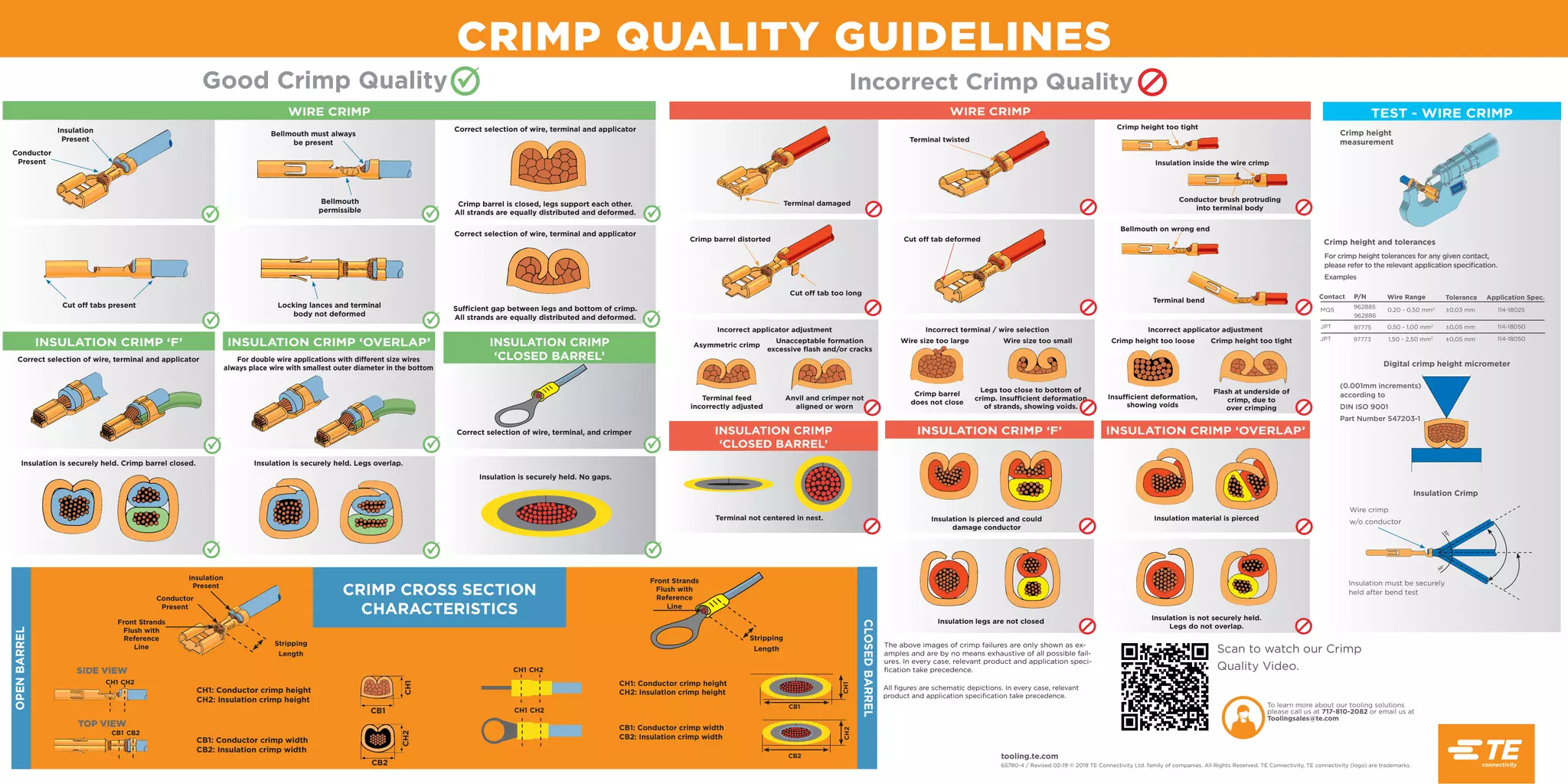
CRIMP QUALITY GUIDELINES tooling.te.com 65780-4
/ Revised 02-19 © 2019 TE Connectivity Ltd. family of companies. All Rights Reserved. TE Connectivity, TE connectivity (logo) are trademarks. All figures are schematic depictions. In every case, relevant product and application specification take precedence. Incorrect Crimp Quality WIRE CRIMP INSULATION CRIMP ‘F’ INSULATION CRIMP ‘OVERLAP’ INSULATION CRIMP ‘CLOSED BARREL’ Terminal damaged Crimp barrel distorted Incorrect applicator adjustment Asymmetric crimp Wire size too large Crimp height too loose Insufficient deformation, showing voids Insulation is pierced and could damage conductor Insulation material is pierced Insulation legs are not closed Insulation is not securely held. Legs do not overlap. Terminal feed incorrectly adjusted Crimp barrel does not close Unacceptable formation excessive flash and/or cracks Wire size too small Crimp height too tight Flash at underside of crimp, due to over crimping Anvil and crimper not aligned or worn Legs too close to bottom of crimp. Insufficient deformation of strands, showing voids. Incorrect terminal / wire selection Incorrect applicator adjustment Cut off tab deformed Cut off tab too long Terminal twisted Crimp height too tight Bellmouth on wrong end Terminal bend Insulation inside the wire crimp Conductor brush protruding into terminal body The above images of crimp failures are only shown as ex- amples and are by no means exhaustive of all possible fail- ures. In every case, relevant product and application speci- fication take precedence. Terminal not centered in nest. Good Crimp Quality WIRE CRIMP INSULATION CRIMP ‘F’ INSULATION CRIMP ‘OVERLAP’ INSULATION CRIMP ‘CLOSED BARREL’ Insulation Present Bellmouth must always be present Correct selection of wire, terminal and applicator Correct selection of wire, terminal and applicator Correct selection of wire, terminal and applicator For double wire applications with different size wires always place wire with smallest outer diameter in the bottom Insulation is securely held. Crimp barrel closed. Insulation is securely held. Legs overlap. Crimp barrel is closed, legs support each other. All strands are equally distributed and deformed. Sufficient gap between legs and bottom of crimp. All strands are equally distributed and deformed. Bellmouth permissible Cut off tabs present Locking lances and terminal body not deformed Conductor Present Correct selection of wire, terminal, and crimper Insulation is securely held. No gaps. To learn more about our tooling solutions please call us at 717-810-2082 or email us at Toolingsales@te.com Scan to watch our Crimp Quality Video. TEST - WIRE CRIMP Crimp height measurement Crimp height and tolerances For crimp height tolerances for any given contact, please refer to the relevant application specification. Examples Contact P/N Wire Range Tolerance Application Spec. MQS JPT JPT 962886 0,20 - 0,50 mm2 962885 ±0,03 mm 114-18025 97775 97773 0,50 - 1,00 mm2 1,50 - 2,50 mm2 ±0,05 mm ±0,05 mm 114-18050 114-18050 (0.001mm increments) according to DIN ISO 9001 Part Number 547203-1 Digital crimp height micrometer Insulation Crimp Wire crimp w/o conductor Insulation must be securely held after bend test 3 0 ° 30° Stripping Length Front Strands Flush with Reference Line Conductor Present Insulation Present CH1: Conductor crimp height CH2: Insulation crimp height CB1: Conductor crimp width CB2: Insulation crimp width OPEN BARREL CLOSED BARREL CH1 CH2 SIDE VIEW TOP VIEW CB1 CB2 CH1: Conductor crimp height CH2: Insulation crimp height CB1: Conductor crimp width CB2: Insulation crimp width CB1 CB2 CH1 CH2 Front Strands Flush with Reference Line Stripping Length CH1 CH2 CH1 CH2 CH2 CH1 CB1 CB2 CRIMP CROSS SECTION CHARACTERISTICS
Download