YALE (A938) ERC50VHS LIFT TRUCK Service Repair Manualuejjdksemme
This is the Highly Detailed factory service repair manual for theYALE (A938) ERC50VHS LIFT TRUCK, this Service Manual has detailed illustrations as well as step by step instructions,It is 100 percents complete and intact. they are specifically written for the do-it-yourself-er as well as the experienced mechanic.YALE (A938) ERC50VHS LIFT TRUCK Service Repair Workshop Manual provides step-by-step instructions based on the complete dis-assembly of the machine. It is this level of detail, along with hundreds of photos and illustrations, that guide the reader through each service and repair procedure. Complete download comes in pdf format which can work under all PC based windows operating system and Mac also, All pages are printable. Using this repair manual is an inexpensive way to keep your vehicle working properly.
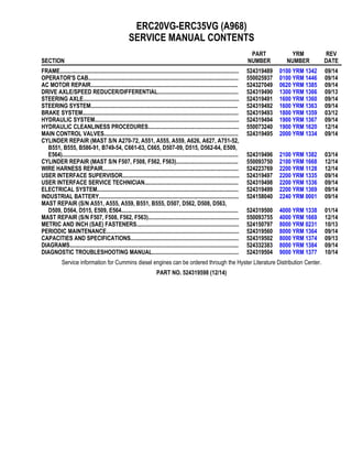
Service Repair Manual Covers:
Frame
Ac motor repair
Drive axle/wet brakes
Steering axle
Steering system
Hydraulic system
Hydraulic cleanliness procedures
Main control valves
Cylinder repair (mast s/n a270-72, a551, a555, a559, a626, a627, a751-52,
B551, b555, b586-91, b749-54, c661-63, c665, d507-09, d515, d562-64, e509,e564)
Wire harness repair
User interface supervisor
User interface service technician
Electrical system
Industrial battery
Mast repairs (s/n a551, a555, a559, a751, a752, b586, b587, b588, b590, b591, b749, b750, b751, b752, and b754)
Metric and inch (sae) fasteners
Diagrams
Periodic maintenance
Capacities and specifications
Diagnostic troubleshooting manual
File Format: PDF
Compatible: All Versions of Windows & Mac
Language: English
Requirements: Adobe PDF Reader
NO waiting, Buy from responsible seller and get INSTANT DOWNLOAD, Without wasting your hard-owned money on uncertainty or surprise! All pages are is great to haveYALE (A938) ERC50VHS LIFT TRUCK Service Repair Workshop Manual.
Looking for some other Service Repair Manual,please check:
https://www.aservicemanualpdf.com/
Thanks for visiting!
YALE (A938) ERC50VHS LIFT TRUCK Service Repair Manualuejjdksemme
This is the Highly Detailed factory service repair manual for theYALE (A938) ERC50VHS LIFT TRUCK, this Service Manual has detailed illustrations as well as step by step instructions,It is 100 percents complete and intact. they are specifically written for the do-it-yourself-er as well as the experienced mechanic.YALE (A938) ERC50VHS LIFT TRUCK Service Repair Workshop Manual provides step-by-step instructions based on the complete dis-assembly of the machine. It is this level of detail, along with hundreds of photos and illustrations, that guide the reader through each service and repair procedure. Complete download comes in pdf format which can work under all PC based windows operating system and Mac also, All pages are printable. Using this repair manual is an inexpensive way to keep your vehicle working properly.
Service Repair Manual Covers:
Frame
Ac motor repair
Drive axle/wet brakes
Steering axle
Steering system
Hydraulic system
Hydraulic cleanliness procedures
Main control valves
Cylinder repair (mast s/n a270-72, a551, a555, a559, a626, a627, a751-52,
B551, b555, b586-91, b749-54, c661-63, c665, d507-09, d515, d562-64, e509,e564)
Wire harness repair
User interface supervisor
User interface service technician
Electrical system
Industrial battery
Mast repairs (s/n a551, a555, a559, a751, a752, b586, b587, b588, b590, b591, b749, b750, b751, b752, and b754)
Metric and inch (sae) fasteners
Diagrams
Periodic maintenance
Capacities and specifications
Diagnostic troubleshooting manual
File Format: PDF
Compatible: All Versions of Windows & Mac
Language: English
Requirements: Adobe PDF Reader
NO waiting, Buy from responsible seller and get INSTANT DOWNLOAD, Without wasting your hard-owned money on uncertainty or surprise! All pages are is great to haveYALE (A938) ERC50VHS LIFT TRUCK Service Repair Workshop Manual.
Looking for some other Service Repair Manual,please check:
https://www.aservicemanualpdf.com/
Thanks for visiting!
Ever been troubled by the blinking sign and didn’t know what to do?
Here’s a handy guide to dashboard symbols so that you’ll never be confused again!
Save them for later and save the trouble!
Things to remember while upgrading the brakes of your carjennifermiller8137
Upgrading the brakes of your car? Keep these things in mind before doing so. Additionally, start using an OBD 2 GPS tracker so that you never miss a vehicle maintenance appointment. On top of this, a car GPS tracker will also let you master good driving habits that will let you increase the operational life of your car’s brakes.
Core technology of Hyundai Motor Group's EV platform 'E-GMP'Hyundai Motor Group
What’s the force behind Hyundai Motor Group's EV performance and quality?
Maximized driving performance and quick charging time through high-density battery pack and fast charging technology and applicable to various vehicle types!
Discover more about Hyundai Motor Group’s EV platform ‘E-GMP’!
What Exactly Is The Common Rail Direct Injection System & How Does It WorkMotor Cars International
Learn about Common Rail Direct Injection (CRDi) - the revolutionary technology that has made diesel engines more efficient. Explore its workings, advantages like enhanced fuel efficiency and increased power output, along with drawbacks such as complexity and higher initial cost. Compare CRDi with traditional diesel engines and discover why it's the preferred choice for modern engines.
5 Warning Signs Your BMW's Intelligent Battery Sensor Needs AttentionBertini's German Motors
IBS monitors and manages your BMW’s battery performance. If it malfunctions, you will have to deal with an array of electrical issues in your vehicle. Recognize warning signs like dimming headlights, frequent battery replacements, and electrical malfunctions to address potential IBS issues promptly.
Fleet management these days is next to impossible without connected vehicle solutions. Why? Well, fleet trackers and accompanying connected vehicle management solutions tend to offer quite a few hard-to-ignore benefits to fleet managers and businesses alike. Let’s check them out!
𝘼𝙣𝙩𝙞𝙦𝙪𝙚 𝙋𝙡𝙖𝙨𝙩𝙞𝙘 𝙏𝙧𝙖𝙙𝙚𝙧𝙨 𝙞𝙨 𝙫𝙚𝙧𝙮 𝙛𝙖𝙢𝙤𝙪𝙨 𝙛𝙤𝙧 𝙢𝙖𝙣𝙪𝙛𝙖𝙘𝙩𝙪𝙧𝙞𝙣𝙜 𝙩𝙝𝙚𝙞𝙧 𝙥𝙧𝙤𝙙𝙪𝙘𝙩𝙨. 𝙒𝙚 𝙝𝙖𝙫𝙚 𝙖𝙡𝙡 𝙩𝙝𝙚 𝙥𝙡𝙖𝙨𝙩𝙞𝙘 𝙜𝙧𝙖𝙣𝙪𝙡𝙚𝙨 𝙪𝙨𝙚𝙙 𝙞𝙣 𝙖𝙪𝙩𝙤𝙢𝙤𝙩𝙞𝙫𝙚 𝙖𝙣𝙙 𝙖𝙪𝙩𝙤 𝙥𝙖𝙧𝙩𝙨 𝙖𝙣𝙙 𝙖𝙡𝙡 𝙩𝙝𝙚 𝙛𝙖𝙢𝙤𝙪𝙨 𝙘𝙤𝙢𝙥𝙖𝙣𝙞𝙚𝙨 𝙗𝙪𝙮 𝙩𝙝𝙚 𝙜𝙧𝙖𝙣𝙪𝙡𝙚𝙨 𝙛𝙧𝙤𝙢 𝙪𝙨.
Over the 10 years, we have gained a strong foothold in the market due to our range's high quality, competitive prices, and time-lined delivery schedules.
In this presentation, we have discussed a very important feature of BMW X5 cars… the Comfort Access. Things that can significantly limit its functionality. And things that you can try to restore the functionality of such a convenient feature of your vehicle.
"Trans Failsafe Prog" on your BMW X5 indicates potential transmission issues requiring immediate action. This safety feature activates in response to abnormalities like low fluid levels, leaks, faulty sensors, electrical or mechanical failures, and overheating.
What Does the PARKTRONIC Inoperative, See Owner's Manual Message Mean for You...Autohaus Service and Sales
Learn what "PARKTRONIC Inoperative, See Owner's Manual" means for your Mercedes-Benz. This message indicates a malfunction in the parking assistance system, potentially due to sensor issues or electrical faults. Prompt attention is crucial to ensure safety and functionality. Follow steps outlined for diagnosis and repair in the owner's manual.
Comprehensive program for Agricultural Finance, the Automotive Sector, and Empowerment . We will define the full scope and provide a detailed two-week plan for identifying strategic partners in each area within Limpopo, including target areas.:
1. Agricultural : Supporting Primary and Secondary Agriculture
• Scope: Provide support solutions to enhance agricultural productivity and sustainability.
• Target Areas: Polokwane, Tzaneen, Thohoyandou, Makhado, and Giyani.
2. Automotive Sector: Partnerships with Mechanics and Panel Beater Shops
• Scope: Develop collaborations with automotive service providers to improve service quality and business operations.
• Target Areas: Polokwane, Lephalale, Mokopane, Phalaborwa, and Bela-Bela.
3. Empowerment : Focusing on Women Empowerment
• Scope: Provide business support support and training to women-owned businesses, promoting economic inclusion.
• Target Areas: Polokwane, Thohoyandou, Musina, Burgersfort, and Louis Trichardt.
We will also prioritize Industrial Economic Zone areas and their priorities.
Sign up on https://profilesmes.online/welcome/
To be eligible:
1. You must have a registered business and operate in Limpopo
2. Generate revenue
3. Sectors : Agriculture ( primary and secondary) and Automative
Women and Youth are encouraged to apply even if you don't fall in those sectors.
Why Is Your BMW X3 Hood Not Responding To Release CommandsDart Auto
Experiencing difficulty opening your BMW X3's hood? This guide explores potential issues like mechanical obstruction, hood release mechanism failure, electrical problems, and emergency release malfunctions. Troubleshooting tips include basic checks, clearing obstructions, applying pressure, and using the emergency release.
2. General
DESCRIPTION
This section contains a description and service
procedures for the parts of the frame. These parts
include the frame, counterweight assembly, overhead
guard, hood and seat assembly, access panels, and
labels.
Throughout this section, forward will refer to travel in
the direction of the forks and left and right will be
determined by an operator sitting in the seat facing
forward. See Figure 1.
A. LEFT SIDE
B. RIGHT SIDE
C. FORWARD TRAVEL
Figure 1. Truck Orientation
If a torque value is not specified, go to Metric and
Inch (SAE) Fasteners 8000YRM0231 for torque
values.
FRAME
The frame is a single weldment with mounts for:
• Counterweight
• Overhead guard
• Tilt cylinders
• Drive axle, or if equipped, transaxle
• Floor plate and pedals
• Side step and fender weldments
• Hood and seat assembly
• Front drop-in bulkhead for lift truck models
ERC40-55VH, ERC50VHS (ERC80-120VH,
ERC100VHS) (A938)
See Figure 2 for lift truck models
• ERC22-35VG (ERC045-070VG) (A968)
See Figure 3 for lift truck models
• ERC16-20VA (ERC030-040VA) (A969)
See Figure 4 for lift truck models
• ERP22-35VL (ERP045-070VL) (A976)
See Figure 5 for lift truck models
• ERP40-50VM, ERP50-55VM6
(ERP080-120VM, ERP100VML) (A985)
See Figure 6 for lift truck models
• ERC40-55VH, ERC50VHS (ERC80-120VH,
ERC100VHS) (A938)
0100 YRM 1342 General
1
3. 1. FRONT OVERHEAD GUARD MOUNTING
BRACKET
2. REAR OVERHEAD GUARD MOUNTING
BRACKET
3. COUNTERWEIGHT MOUNTING PLATE
4. FRONT BULKHEAD
5. RIGHT FRAME CHANNEL
6. LEFT FRAME CHANNEL
7. REAR BULKHEAD
8. TILT ANCHOR PLATE
9. SIDE STEP MOUNTING BRACKET
Figure 2. Frame Weldment for Lift Truck ERC22-35VG (ERC045-070VG) (A968)
General 0100 YRM 1342
2
4. 1. FRONT OVERHEAD GUARD MOUNTING
BRACKET
2. REAR OVERHEAD GUARD MOUNTING
BRACKET
3. COUNTERWEIGHT MOUNTING PLATE
4. FRONT BULKHEAD
5. RIGHT FRAME CHANNEL
6. LEFT FRAME CHANNEL
7. REAR BULKHEAD
8. TILT ANCHOR PLATE
9. SIDE STEP MOUNTING BRACKET
Figure 3. Frame Weldment for Lift Truck ERC16-20VA (ERC030-040VA) (A969)
0100 YRM 1342 General
3
5. 1. FRONT OVERHEAD GUARD MOUNTING
BRACKET
2. OPERATOR MODULE PLATE
3. FRONT BULKHEAD
4. REAR BULKHEAD
5. COUNTERWEIGHT MOUNTING PLATE
6. LEFT FENDER
7. RIGHT FENDER
8. RIGHT FRAME CHANNEL
9. LEFT FRAME CHANNEL
10. TILT ANCHOR PION
11. DRIVE AXLE MOUNTS
12. SIDE STEP MOUNTING BRACKET
Figure 4. Frame Weldment for Lift Truck ERP22-35VL (ERP045-070VL) (A976)
General 0100 YRM 1342
4
6. 1. FRONT OVERHEAD GUARD MOUNTING
BRACKET
2. OPERATOR MODULE PLATE
3. FRONT BULKHEAD
4. REAR BULKHEAD
5. COUNTERWEIGHT MOUNTING PLATE
6. LEFT FENDER
7. RIGHT FENDER
8. RIGHT FRAME CHANNEL
9. LEFT FRAME CHANNEL
10. TILT ANCHOR PION
11. DRIVE AXLE MOUNTS
12. SIDE STEP MOUNTING BRACKET
Figure 5. Frame Weldment for Lift Truck ERP40-50VM, ERP50-55VM6 (ERP080-120VM, ERP100VML)
(A985)
0100 YRM 1342 General
5
7. 1. FRONT OVERHEAD GUARD MOUNTING
BRACKET
2. REAR OVERHEAD GUARD MOUNTING
BRACKET
3. COUNTERWEIGHT MOUNTING PLATE
4. FRONT BULKHEAD
5. RIGHT FRAME CHANNEL
6. LEFT FRAME CHANNEL
7. REAR BULKHEAD
8. TILT ANCHOR PLATE
9. SIDE STEP MOUNTING BRACKET
Figure 6. Frame Weldment for Lift Trucks ERC40-55VH, ERC50VHS (ERC80-120VH, ERC100VHS) (A938)
The hydraulic and traction motor electronic controllers
and contactors are located in the counterweight cavity
for the following lift truck models
• ERC22-35VG (ERC045-070VG) (A968)
• ERC16-20VA (ERC030-040VA) (A969)
• ERC40-55VH, ERC50VHS (ERC80-120VH,
ERC100VHS) (A938)
The hydraulic motor electronic controller and
contactor are located in the counterweight cavity and
the traction motor controller is attached to the front
bulkhead for the following lift truck models
• ERP22-35VL (ERP045-070VL) (A976)
• ERP40-50VM, ERP50-55VM6
(ERP080-120VM, ERP100VML) (A985)
NOTE: Lift truck models ERC22-35VG
(ERC045-070VG) (A968) manufactured after June,
2012 are equipped with a removable floor plate that
requires no tools to remove.
For all lift truck models covered in this Service
Manual, the Vehicle Systems Manager (VSM) is
either mounted on or near the front bulkhead
underneath the floor mat and floor plate.
General 0100 YRM 1342
6
8. DISCHARGING THE CAPACITORS
WARNING
DO NOT make repairs or adjustments unless you
have been properly trained and authorized to do
so. Improper repairs and adjustments can create
dangerous operating conditions. DO NOT operate
a lift truck that needs repairs. Report the need for
repairs to your supervisor immediately. If repair is
necessary, attach a DO NOT OPERATE tag on the
steering wheel and disconnect the battery.
Disconnect the battery and allow the capacitors to
discharge before opening any compartment
covers or inspecting or repairing the electrical
system. DO NOT place tools on top of the battery.
If a tool causes a short circuit, the high current
flow from the battery can cause personal injury or
property damage.
Some checks and adjustments are performed with
the battery connected. DO NOT connect the
battery until the procedure instructs you to do so.
Never wear any metallic items on your fingers,
arms, or neck. Metal items can accidentally make
an electrical connection and cause injury.
Before performing any tests or adjustments, block
the lift truck to prevent unexpected movement.
The capacitor in the transistor controller(s) can
hold an electrical charge for about 10 seconds
after the battery is disconnected. To prevent an
electrical shock and personal injury, discharge
the capacitor(s) before inspecting or repairing any
component in the drive unit compartment. Make
certain that the battery has been disconnected.
DO NOT short across the motor controller
terminals with a screwdriver or jumper wire.
Make certain the Emergency-Disconnect switch
has not been activated. This will isolate the
controller and prevent the capacitors from
discharging properly. The proper way to
disconnect the battery is by separating the battery
connectors.
1. Ensure the capacitors are discharged by
performing Step 2 through Step 6 below.
2. Turn the key or keyless switch to the OFF
position.
3. Disconnect the battery by separating the
connectors.
4. Block the drive wheels to prevent the lift truck
from moving.
5. Make sure the Emergency-Disconnect switch
HAS NOT been activated. If the Emergency-
Disconnect switch is activated, rotate the switch
to the right until it pops up.
6. Press horn button. Wait 30 seconds to be sure
capacitors are fully discharged.
RAPID CHARGE
All the lift trucks covered in this Service Manual may
be equipped with an optional Basic Rapid Charge
System. See Figure 7. Lift truck models ERP22-35VL
(ERP045-070VL) (A976) and ERP40-50VM,
ERP50-55VM6 (ERP080-120VM, ERP100VML)
(A985) may also be equipped with an optional
Integrated (Quick Disconnect) Rapid Charge System.
See Figure 8 or Figure 9.
On lift trucks equipped with either Rapid Charge
System, the battery is charged during operator breaks
or when the lift truck is not being used. Both systems
provide extended operation with a single battery.
Connect or disconnect battery from the Rapid Charge
System using the battery connectors.
Some of the features of the Basic Rapid Charge
System include (see Figure 7):
• Battery connector externally mounted for easy
access.
• Vented side covers for improved battery
cooling.
• Requires rapid charge vented battery and
sealed battery fan box with thermostat.
Some of the features of the Integrated (Quick
Disconnect) Rapid Charge System include (see
Figure 8 or Figure 9):
• Power cables from hood mounted connector
are wired to the existing truck battery
connections, eliminating the need to run cables
from the battery to the top side of hood.
• The Integrated Rapid Charge System easily
supports rapid, fast, and convenient charging.
0100 YRM 1342 General
7
9. • Cutouts in the battery compartment side panel
are standard with the Integrated Rapid Charge
System and help support vented tray batteries
and batteries with side-mounted cooling fans.
• An interlock switch on the hood mounted
connector housing door prevents truck from
being operated during charging.
NOTE: LIFT TRUCK MODELS ERP22-35VL
(ERP045-070VL) (A976) SHOWN.
1. RAPID CHARGE CONNECTOR
2. VENTED SIDE COVER
Figure 7. Basic Rapid Charge System
General 0100 YRM 1342
8
11. Thank you very much for
your reading. Please Click
Here. Then Get COMPLETE
MANUAL. NO WAITING
NOTE:
If there is no response to
click on the link above,
please download the PDF
document first and then
click on it.
12. 1. SIDE PANEL CUTOUT
2. COVER
3. BATTERY CABLES
4. INTERLOCK SWITCH
5. BATTERY CONNECTOR
Figure 9. Integrated (Quick Connect) Rapid Charge System, Lift Truck Models ERP40-50VM, ERP50-55VM6
(ERP080-120VM, ERP100VML) (A985)
GROUND TEST
NOTE: If the static discharge ground connection is
not secured properly, it could lead to the possible
failure of the traction motor and/or pump motor
controller.
To ensure proper installation of seat assembly and
associated bracketing, perform continuity test as
described below:
1. Using an ohm meter, place a test lead at the
armrest mounting bolt and another at the truck
frame. The resistance needs to read 5 Ohms or
less. See Figure 10.
2. If resistance is greater than 5 Ohms, double
check installation of seat assembly, both ends of
seat wiring harness, and wiring harness ground
strap.
General 0100 YRM 1342
10
13. A. ARMREST FOR LIFT TRUCK MODELS
ERC045-070VG (A968), ERC030-040VA (A969),
ERP045-070VL (A976), ERP080-120VM (A985),
AND ERC80-120VH, ERC100VHS (A938)
B. ARMREST FOR LIFT TRUCK MODELS
ERC22-35VG (A968), ERC16-20VA (A969),
ERP22-35VL (A976), ERP40-50VM,
ERP50-55VM6 (A985), AND ERC40-55VH,
ERC50VHS (A938)
1. ARMREST BOLT
2. FRAME
Figure 10. Ground Test
MUD GUARDS
Lift truck models equipped with mud guards will have
mud guards attached to front fender extensions and
suspended between drive wheels and carriage. The
mud guards are not serviceable and should be re-
placed if damaged or no longer providing shielding
from debris.
1. Set parking brake and turn key or keyless switch
to OFF position.
2. Remove capscrew and nut from lift truck frame
and fender extension. Discard mud guard. See
Figure 11.
3. Install new mud guard, capscrew, and nut into
fender extension and frame. Tighten capscrew to
66 N•m (49 lbf ft).
NOTE: STANDARD TREAD MUD GUARD SHOWN.
WIDE TREAD MUD GUARD IS SIMILAR.
1. CAPSCREW
2. NUT
3. MUD GUARD
Figure 11. Mud Guards
0100 YRM 1342
11
14. Covers and Floor Plates
FOR LIFT TRUCK MODELS ERC22-35VG
(ERC045-070VG) (A968)
Various covers and floor plates provide access to
components during service and securely cover areas
during normal operations.
NOTE: Lift truck models ERC22-35VG
(ERC045-070VG) (A968) manufactured after June,
2012 are equipped with a removable floor plate that
requires no tools to remove.
1. Floor mat and floor plates in operator compart-
ment allow access to traction motor, hydraulic
pump and motor, service and parking brakes, and
hydraulic control valve. The floor plate is fastened
to the frame with capscrews and washers. The
manual hydraulic floor plate and e-hydraulic floor
plate hook onto the floor plate. See Figure 12.
2. Counterweight cover is attached to counterweight
by two capscrews and allows access to electrical
controllers. See Figure 12.
3. Manual hydraulic covers protect links during oper-
ation. For removal procedures for these covers
see Main Control Valves 2000YRM1334. See
Figure 12.
4. Hood latch cover is attached to bulkhead using
two capscrews. See Figure 12.
A. MANUAL HYDRAULIC CONTROL LEVERS B. E-HYDRAULIC CONTROL LEVERS
1. COUNTERWEIGHT COVER
2. CAPSCREW
3. HOOD LATCH COVER*
4. MANUAL HYDRAULIC COVERS
5. MANUAL HYDRAULIC FLOOR MAT
6. WASHER
7. MANUAL HYDRAULIC FLOOR PLATE
8. COWL
9. E-HYDRAULIC FLOOR MAT
10. E-HYDRAULIC FLOOR PLATE
11. COUNTERWEIGHT
12. FRAME
13. FLOOR PLATE
*HOOD LATCH COVER USED ON LIFT TRUCKS EQUIPPED WITH EITHER MANUAL OR E-HYDRAULIC
CONTROL LEVERS.
Figure 12. Covers and Floor Plates for Lift Truck Models ERC22-35VG (ERC045-070VG) (A968)
Covers and Floor Plates 0100 YRM 1342
12
15. FOR LIFT TRUCK MODELS ERC16-20VA
(ERC030-040VA) (A969)
Various covers and floor plates provide access to
components during service and securely cover areas
during normal operations.
1. Floor mat and floor plates in operator compart-
ment allow access to traction motor, hydraulic
pump and motor, service and parking brakes, and
hydraulic control valve. The floor plate is fastened
to the frame with capscrews and washers. The
manual hydraulic floor plate and e-hydraulic floor
plate hook onto the floor plate. See Figure 13.
2. Counterweight cover is attached to counterweight
by two capscrews and allows access to electrical
controllers. See Figure 13.
3. Manual hydraulic covers protect links during oper-
ation. For removal procedures for these covers
see Main Control Valves 2000YRM1334. See
Figure 13.
A. E-HYDRAULIC CONTROL LEVERS B. MANUAL HYDRAULIC CONTROL LEVERS
1. COUNTERWEIGHT
2. COUNTERWEIGHT COVER
3. CAPSCREW
4. FRAME
5. COWL
6. E-HYDRAULIC FLOOR PLATE
7. E-HYDRAULIC FLOOR PLATE
8. E-HYDRAULIC FLOOR MAT
9. MANUAL HYDRAULIC COVERS
10. MANUAL HYDRAULIC FLOOR PLATE
11. MANUAL HYDRAULIC FLOOR PLATE
12. MANUAL HYDRAULIC FLOOR MAT
Figure 13. Covers and Floor Plates for Lift Truck Models ERC16-20VA (ERC030-040VA) (A969)
0100 YRM 1342 Covers and Floor Plates
13
16. FOR LIFT TRUCK MODELS ERP22-35VL
(ERP045-070VL) (A976)
Various covers and floor plates provide access to
components during service and securely cover areas
during normal operations.
1. Floor mat and floor plates in operator compart-
ment allow access to service and parking brakes
and hydraulic control valve. The floor plate is fas-
tened to the frame with capscrews and washers.
The manual hydraulic floor plate and e-hydraulic
floor plate hook onto the floor plate. See Fig-
ure 14.
2. Counterweight cover is attached to counterweight
by a tow pin and two capscrews. This cover al-
lows access to electrical controllers, hydraulic
pump and motor, and hydraulic tank. See Fig-
ure 14.
3. Manual hydraulic covers protect links during oper-
ation. For removal procedures for these covers
see Main Control Valves 2000YRM1334. See
Figure 14.
A. E-HYDRAULIC CONTROL LEVERS B. MANUAL HYDRAULIC CONTROL LEVERS
1. COUNTERWEIGHT
2. FRAME
3. COWL
4. COUNTERWEIGHT COVER
5. TOW PIN
6. CAPSCREW
7. MANUAL HYDRAULIC FLOOR PLATE
8. MANUAL HYDRAULIC FLOOR PLATE
9. MANUAL HYDRAULIC FLOOR MAT
10. MANUAL HYDRAULIC COVERS
11. E-HYDRAULIC FLOOR PLATE
12. E-HYDRAULIC FLOOR PLATE
13. E-HYDRAULIC FLOOR MAT
Figure 14. Covers and Floor Plates for Lift Truck Models ERP22-35VL (ERP045-070VL) (A976)
Covers and Floor Plates 0100 YRM 1342
14
17. FOR LIFT TRUCK MODELS ERP40-50VM,
ERP50-55VM6 (ERP080-120VM,
ERP100VML) (A985)
Various covers and floor plates provide access to
components during service and securely cover areas
during normal operations.
1. Floor mat and floor plates in operator compart-
ment allow access to service brakes, hydraulic
control valve, and traction motor electrical control-
ler. The manual hydraulic floor plate and e-hy-
draulic floor plate hook onto the floor plate. See
Figure 15 or Figure 16.
2. Counterweight cover is attached to counterweight
by three captive capscrews. This cover allows ac-
cess to hydraulic pump electrical controller, hy-
draulic pump and motor, and hydraulic tank. See
Figure 15 or Figure 16.
3. Manual hydraulic covers protect links during oper-
ation. For removal procedures for these covers
see Main Control Valves 2000YRM1334. See
Figure 15 or Figure 16.
A. MANUAL HYDRAULIC CONTROL LEVERS B. E-HYDRAULIC CONTROL LEVERS
1. CAPTIVE CAPSCREW
2. COUNTERWEIGHT COVER
3. COUNTERWEIGHT
4. MANUAL HYDRAULIC FLOOR MAT
5. MANUAL HYDRAULIC FLOOR PLATE
6. MANUAL HYDRAULIC FLOOR PLATE
7. FRAME
8. MANUAL HYDRAULIC COVERS
9. COWL
10. E-HYDRAULIC FLOOR MAT
11. E-HYDRAULIC FLOOR PLATE
12. E-HYDRAULIC FLOOR PLATE
Figure 15. Covers and Floor Plates for Lift Truck Models ERP40-50VM, ERP50-55VM6 (ERP080-120VM,
ERP100VML) (A985) Manufactured Before Nov, 2014
0100 YRM 1342 Covers and Floor Plates
15