1. The World’s Best Compressors™
For Gas Compression
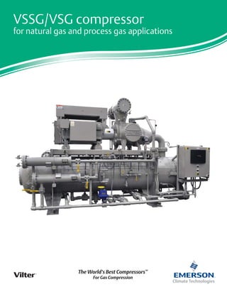
VSSG/VSG compressor
for natural gas and process gas applications
2. Why choose a Vilter™
single screw compressor?
Vilter’s VSSG/VSG single screw gas compressors deliver longer life, higher reliability and better energy efficiency than
twin screw compressors and have fewer moving parts than reciprocating compressors. The key to the single screw
compressor’s reliability is in its balanced design. At the core of the positive displacement rotary compressor is a single main
rotor intermeshed with two opposing gaterotors. The balanced design results in ultra-low bearing loads with significantly
decreased vibration and sound levels. The key to the single screw compressor’s high energy efficiency is Vilter’s exclusive
Parallex™
slide system allowing the compressor to run at optimum efficiency through its full range of capacity.
Part load energy consumption –
single screw vs. twin screw
Isentropic efficiency comparison
between variable and fixed volume
Applications
• Gas liquification
• Vapor recovery
• Flare gas recovery
• Coal bed methane recovery
• Field and fuel gas boosting
• Wellhead recovery
• Enhanced oil recovery
• Landfill gas recovery
• LNG boil off
• Gas gathering
• BIO - gas
• Digester
• CO2
• Nitrogen
• Hydrogen
• Refrigerant
Features and benefits
•Displacements from 310 to 2,048 CFM
• Variable capacity control 10-100%
• Variable volume ratios 1.2 – 7.0
• Compression ratios 2 – 20
• Electronic actuators are weatherproof
and conform to Class 1, Group C&D,
Division 2 Classification
• Balanced main rotor with no axial or
radial loads
• Parallex™
slide system for maximum
operating efficiency
• Low bearing loads – no hydrodynamic bearings
• High suction pressure capability is standard
• Clockwise rotation models available
• Low noise levels
• Low maintenance costs
Parallex™
slide system
It’s the key to part load efficiencies far superior to twin screw compressors.
Capacity and volume slides move independently of each other based on
load, eliminating over or under compression and saving motor horsepower.
Allen-Bradley programmable controller
The CompactLogix programmable controller with an A-B PanelView 1000
graphic display provides high performance in a small footprint for stand
alone operation or for integrated system control.
Large capacity oil filter
Filters will remove all particles, 25 microns or larger, from the oil before the
compressor. Filter assemblies are equipped with transducers to measure
pressure drop and shut-off valves for isolation and servicing.
Oil cooling options
• Water cooled
• Air cooled
3. Unit features
Standard construction
• Main bearings – Roller and ball type angular contact
thrust.
• Gaterotor bearings – Roller and ball type angular contact
thrust.
• Hand wheels or optical slide valve motor for capacity and
volume control. Suitable for Class 1, Group C+D, Div. II.
• Variable vi - Independent volume control and capacity
control for improving efficiencies.
• Separate prelube oil pump with TEFC drive motor.
• Lube oil piping is carbon steel, using socket weld or butt
weld connections. Threaded connections are kept to a
minimum.
• ASME designed oil separator with coalesing oil filter.
• CompactLogix programmable controller with an A-B
PanelView 1000 graphic display
• Separate stop and check valves for both suction and
discharge lines.
Process gas circuit
• Suction gas stop and check valve.
• Suction line strainer – The strainer is stainless steel mesh
construction and suited to process gas applications.
• Process gas/oil separator – The separator is capable of
removing the oil from the discharge gas stream and is an
ASME-coded vessel which uses five stages of separation to
achieve an oil loss of below 4 ppm.
• Discharge oil separator relief valve.
Injection oil circuit
• Oil prelube pump with TEFC motor.
• Oil cooler/temperature control valve – An oil cooler,
either air or water cooled, must be used to remove the
heat of compression from the oil stream. A two way
temperature control valve is used to maintain precise oil
injection temperature to the compressor VIA PID loop
control in PLC
• Oil filtration – Filtration down to 25 microns nominal.
Optional dual filters are recommended to allow
replacement of one cartridge while the compressor
continues running with the other cartridge in service
• Oil heater –Oil heaters are supplied to maintain oil
temperature of at least 90°F when the compressor is
not running
Available options
• Stainless steel lube oil circuit
• Suction bypass connection for fuel gas booster application
• Dual oil pumps
• Dual oil filters
• Water cooled or air cooled oil coolers
• High and low ambient temperature options
Note – Because the oil system on the VSSG/VSG compressor utilizes
discharge gas pressure as the means to move the injection oil through the
system, it must be remembered that all components of the oil system are
exposed to full discharge pressure and must be pressure rated accordingly.
Flow Diagram (Figure 1)
4. Instrumentation
Pressure
There are four pressure transducers to read system pressures
as listed below (Figure 1).
PT1 suction pressure transducer
(-15.0 - 400 PSIG) measures the gas suction pressure into
the compressor housing.
PT2 discharge pressure transducer
(-15.0 - 400 PSIG) measures the discharge pressure of the
process gas in the separator.
PT3 oil filter inlet pressure transducer
(-15.0 - 400 PSIG) measures the oil pressure as it enters the
oil filter canisters.
PT4 oil manifold pressure transducer
(-15.0 - 400 PSIG) measures the oil pressure downstream
of the oil filter as the oil is injected into the compressor.
Additional pressure transducers may be required and installed by the cus-
tomer for pressure readings at customer specified points such as process gas
discharge pressure from the package boundary, cooling water pressure to
and/or from the oil cooler, etc.
Temperature
There are four temperature readings for processor control, as
listed below (Figure 1).
RTD1 suction temperature RTD
measures the temperature of the incoming suction gas.
RTD2 discharge temperature RTD
measures the temperature of the gas/oil mixture as it is
discharged from the compressor housing.
RTD3 oil separator temperature RTD
measures the temperature of the oil in the separator sump.
RTD4 oil Injection temperature RTD
measures the temperature of the oil as it is injected into
the compressor.
Additional RTD’s may be required and installed by the customer for
temperature readings at customer specified points such as discharge gas
temperature from the package boundary, cooling water temperature to and/
or from the oil cooler, gas aftercooler temperature, etc.
Additional instrumentation
• Motor current transformer
• Optical actuators for capacity and volume slide indication
Other options
• Remote start/stop input
• Remote alarm/trip output
Alarm and shutdown annunciation/indication
The control system for the VSSG/VSG compressor must
protect the machine from running outside of normal
operating conditions. This is accomplished by providing
operators with alarms when operating parameters have
reached an abnormal condition, and by automatically
stopping the compressor before these conditions can
cause a unit failure.
Safety setpoints:
• Low gas suction temperature
• High gas discharge temperature
• Low oil separator start temperature
• Low oil separator run temperature
• Low oil injection temperature
• High oil injection temperature
• Low suction pressure
• High discharge pressure
• Prelube oil pressure
• Low oil pressure
• High starting oil filter differential pressure
• High running oil filter differential pressure
• High motor amperage limit
In most cases, the safety setpoints described will have
settings which are dictated by process requirements, and
not necessarily mechanical constraints of the compressor.
Process pressures and temperatures may vary considerably
depending on the application of the compressor. The VSSG/
VSG compressor is designed to operate in a broad range of
applications. Minimum and maximum values for each safety
setpoint are provided, while precise settings for the safety
setpoints must be derived for each installation.
5. Application guidelines
To ensure the successful operation of the VSSG/VSG com-
pressor, the guidelines described below should be followed.
Proper lubrication is critical to the operation of the VSSG/
VSG compressor. The compressor relies on the injected oil
to absorb and remove the heat of compression, to seal the
compression chambers formed in the flutes of the screw,
and to lubricate all moving parts. For this reason, it is
imperative that the oil chosen be of correct viscosity, and
that sufficient oil flow be provided at all times, using an
auxiliary oil pump when necessary. The oil chosen must be
compatible with the process gas, to prevent absorption of
the gas into the oil, which would dilute the oil and reduce
the viscosity. Also oil filtration to 25 micron nominal
particle size is required to ensure that only clean oil is
injected into the compressor. For assistance in choosing
the correct oil for the application and in sizing an auxiliary
oil pump, consult a Vilter representative.
Injection oil temperature must be closely controlled for
optimum performance. Oil temperature must be maintained
a minimum of 15 - 20°F above the gas mixture dewpoint at
anytime to prevent condensation or liquid knockout from
occurring within the compressor.
Gas composition plays a role in the performance of the
VSSG/VSG compressor as well. While the VSSG/VSG is
capable of handling a wide variety of gases, if H2
S is present
in the process gas in any concentration, special oil additives
are required to protect the compressor from corrosion.
Levels below 100 PPM of H2
S allow the standard warranty
to apply.
Typical gases handled: Natural gas, landfill gas, carbon
dioxide, propane, helium, propylene and ammonia.
Other gases will need to be reviewed for compatibility
and operational performance by Vilter.
VSG compressor capacity and design limitations - standard models
Description
VSG
301
VSG
361
VSG
401
VSG
501
VSG
601
VSG
701
VSG
751
VSG
901
VSG
791
VSG
891
VSG
1051
VSG
1201
VSG
1301
VSG
1551
VSG
1851
VSG
2101
VSG
2401
VSG
2601
VSG
2801
VSG
3001
Rotor diameter (mm) 205 240 280 310 312 350 401 401
Gaterotor diameter (mm) 195 205 216 225 240 252 268 280 289 300 298 310 312 331 350 368 388 400 411 416
Max. HP 3600 RPM* 300 HP 500 HP 675 HP 2000 HP 675 HP 1000 HP 2000 HP
Max. allowable torque (ft. lbs.) 444 739 998 2958 998 1479 2958
Rotor speed (RPM) 1200-4200 1200-4000 1200-3800
Direction of rotation
CCW facing
drive end
CW facing
drive end
CCW facing drive end
Drive type Direct drive, electric motor, gas engine
Built-in volume ratio 1.2 to 7.0 (Continuously variable automatic, or manual control)
Capacity range 10% to 100% (Continuously variable automatic, or manual control)
Bare comp. MAWP (psig)** 515 485 1100 485 535
Max. pressure differential
(psig)***
325
Min. inlet temp. (°F) -50°F
Max. inlet temp. (°F) 180°F
Max. disch. temp. (°F) 225° (Contact Vilter for increased temperature limits)
Max. oil temp. (°F) 190° (Contact Vilter for increased temperature limits)
*Higher limits are available. Consult Vilter Manuafacturing LLC.
**Higher discharge pressures are achievable. Consult Vilter Manuafacturing LLC. for approval.
***Higher differential pressures can be achieved. Consult Vilter Manuafacturing LLC. for approval.
Note: MAWP (Maximum Allowable Working Pressure). The relief valve setting must be below the MAWP. The relief valve is usually set 10% lower than the MAWP.
6. A B
D
C
A B
C
ROTATION
D
VSG unit dimensions and specifications
Models VSG 301-701, left, are
shown with a standard C-Flange
motor mount, single oil filter
and standard water-cooled oil
cooler which is noted by the D
dimension on the drawing.
Models VSG 751-3001 drawings
illustrate the optional dual oil
filter and the optional remote
mounted oil cooler which can
be air cooled.
It is important to note that all
VSG models can be fitted with
single or dual oil filters, water-
cooled oil cooler or remote
mounted oil cooler.
Models VSG 301-701
Models VSG 751-3001
VSG unit dimensions
Vilter model
Standard connection size* Unit dimensions (approx.)*
Approx. shipping
weight (lbs)**Suction Discharge
A
Length
B
Width
C
Height
D
Optional oil cooler
VSG-301 3” 3” 8’-10” 4’-2” 6’ 7-3/4” 7000
VSG-361 3” 3” 8’-10” 4’-2” 6’ 7-3/4” 7300
VSG-401 3” 3” 8’-10” 4’-2” 6’ 7-3/4” 7500
VSG-501 4” 3” 8’-9” 3’-8” 7’-6” 10-3/4” 8500
VSG-601 4” 4” 9’-10” 4’ 7’-10” 10-3/4” 8800
VSG-701 4” 4” 9’-10” 4’ 7’-10” 10-3/4” 9000
VSG-751 6” 4” 12’ 3’-7” 8’ 16” 14800
VSG-901 6” 4” 12’ 3’-7” 8’ 16” 15200
VSG-791 6” 4” 12’ 3’-7” 8’ 16” 14800
VSG-891 6” 4” 12’ 3’-7” 8’ 16” 15200
VSG-1051 6” 6” 13’-2” 4’-1” 8’-8” 16” 15500
VSG-1201 6” 6” 13’-2” 4’-1” 8’-10” 16” 16000
VSG-1301 6” 6” 13’-2” 4’-1” 8’-10” 16” 16000
VSG-1551 8” 6” 15’ 5’-8” 10’ 17” 18000
VSG-1851 8” 6” 15’ 5’-8” 10’ 17” 18200
VSG-2101 10” 6” 15’ 5’-8” 10’ 17” 18500
VSG-2401 12” 8” 17’-4” 7’-4” 11’-4” 17” 19000
VSG-2601 12” 8” 17’-4” 7’-4” 11’-4” 17” 19000
VSG-2801 12” 8” 17’-4” 7’-4” 11’-4” 17” 19200
VSG-3001 12” 8” 17’-4” 7’-4” 11’-4” 17” 19500
*Dimensions shown are approximate and should not be used for construction.
** Typical motor weight used, actual weight may differ.
7. A B
C
Models VSSG 291-601 drawings il-
lustrate the optional dual oil filter
and the air cooled connections.
It is important to note that all
VSSG models can be fitted with
single or dual oil filters, wa-
tercooled oil cooler or remote
mounted oil cooler.
VSSG unit dimensions
Vilter model
Standard connection size* Unit dimensions (approx.)*
Approx.
shipping
weight (lbs)**Suction Discharge
A
Length
B
Width
C
Height
D
Optional oil
cooler
VSSG-291 3” 3” 8’-10” 4’-2” 6’ 7-3/4” 7000
VSSG-341 3” 3” 8’-10” 4’-2” 6’ 7-3/4” 7300
VSSG-451 3” 3” 8’-10” 4’-2” 6’ 7-3/4” 7500
VSSG-601 4” 4” 9’-10” 4’ 7’-10” 10-3/4” 8800
*Dimensions shown are approximate and should not be used for construction.
**Typical motor weight used, actual weight may differ.
VSSG compressor capacity and design limitations - standard models
Description
VSSG
291
VSSG
341
VSSG
451
VSSG
601
Rotor diameter (mm) 240 240 240 240
Gaterotor diameter (mm) 220 225 225 240
Max. HP 3600 RPM* 500 HP
Max. allowable torque 739 ft. lbs.
Rotor speed (RPM)* 1200-4200
Direction of rotation CW Facing Drive End
Drive type Direct drive, electric motor, gas engine
Built-in volume ratio 1.2 to 7.0 (Continuously variable automatic, or manual control)
Capacity range 10% to 100% (Continuously variable automatic, or manual control)
Bare comp. MAWP (psig)** 535
Max. pressure differential
(psig)***
325
Min. inlet temp. (°F) -50°F
Max. inlet temp. (°F) 180°F
Max. disch. temp. (°F) 225° (Contact Vilter for increased temperature limits)
Max. oil temp. (°F) 190° (Contact Vilter for increased temperature limits)
*Higher limits are available. Consult Vilter Manuafacturing LLC.
**Higher discharge pressures are achievable. Consult Vilter Manuafacturing LLC. for approval.
***Higher differential pressures can be achieved. Consult Vilter Manuafacturing LLC. for approval.
Note: MAWP (Maximum Allowable Working Pressure). The relief valve setting must be below the MAWP. The relief valve is usually set 10% lower than the MAWP.
Models VSSG 291-601
VSSG unit dimensions and specifications