Downloaded 43 times


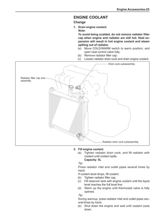


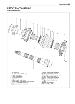
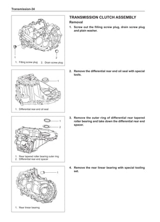
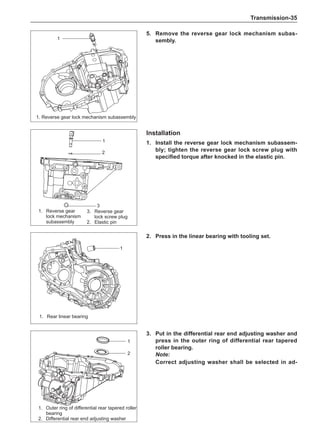


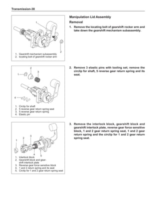


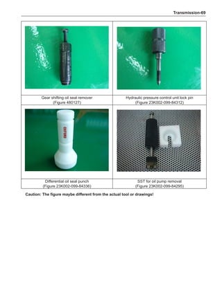
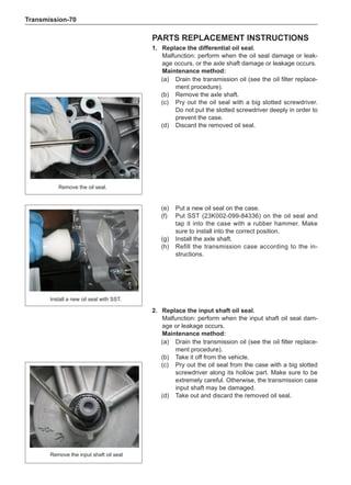
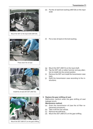
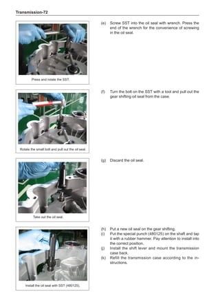
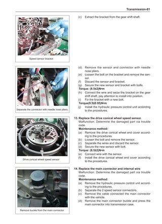


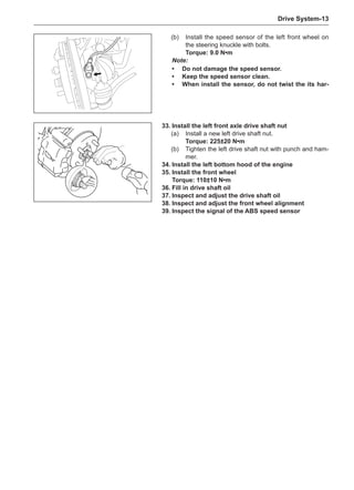

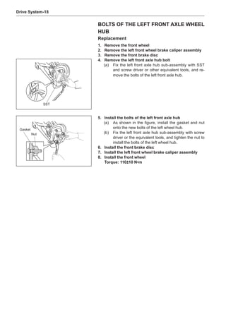
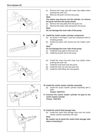


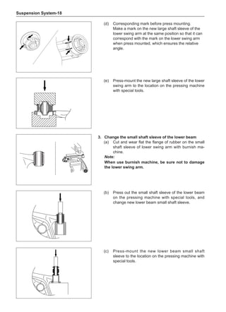


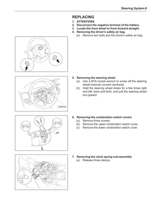
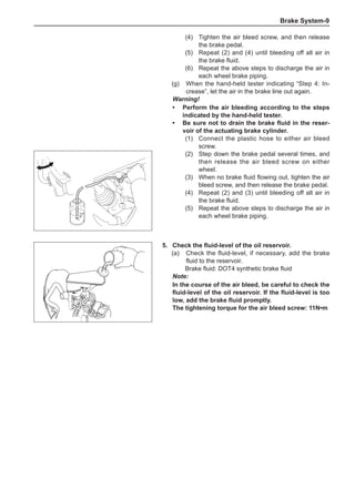
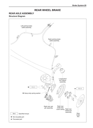
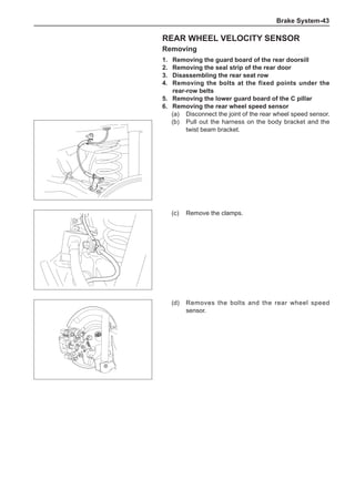
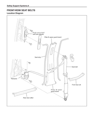
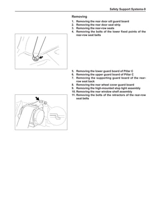
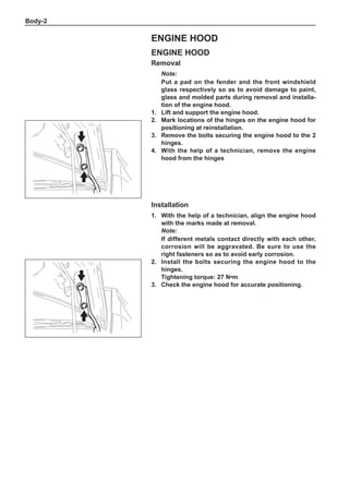
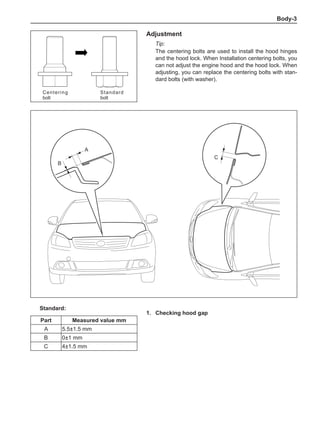
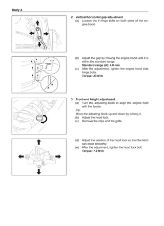
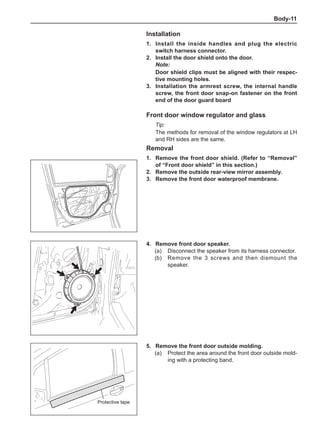
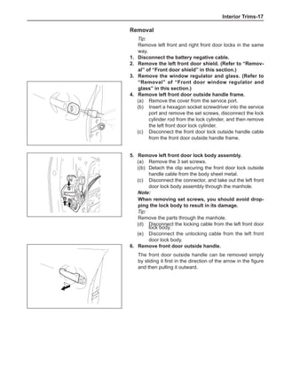
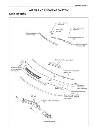
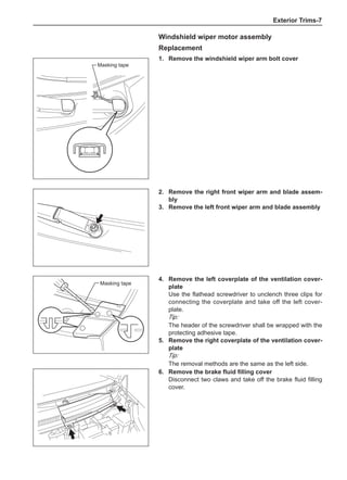
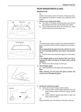
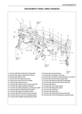
![Suspension System-32
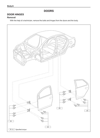
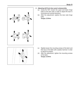
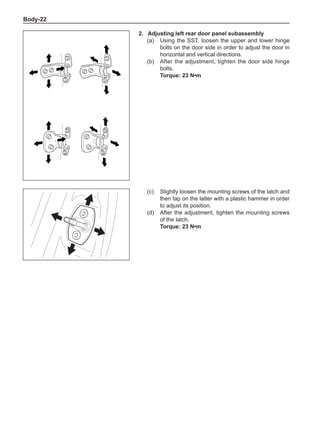
Wheels
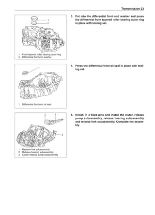
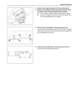
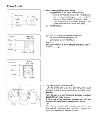
General Balance Steps
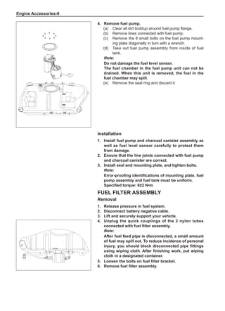
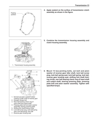
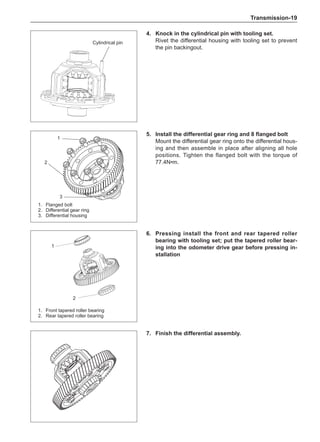
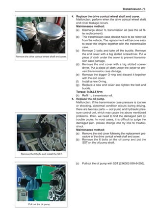
Clean the accumulated soil and other objects on the in-
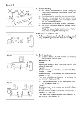
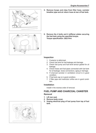
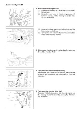
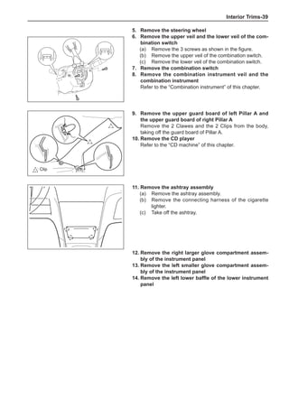
side of the wheel rims.
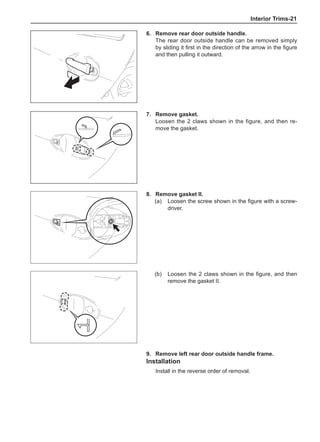
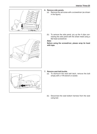
Note:
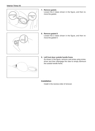
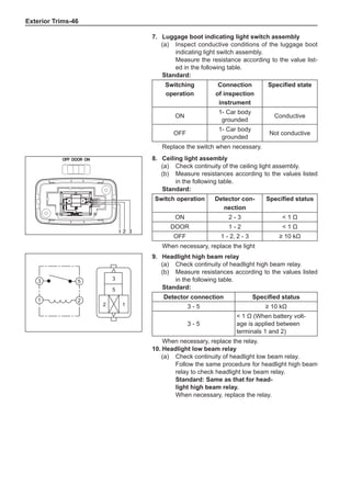
Remove the stone on the tread to prevent it from
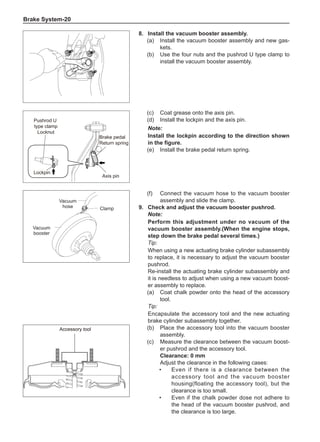
flying off and injuring the operator in the course of
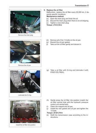
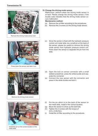
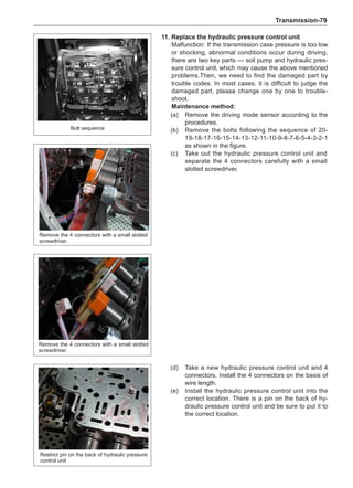
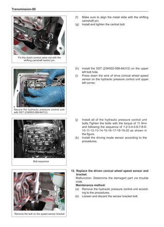
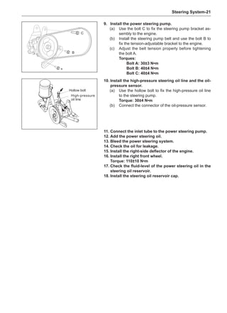
rotary balance. This can achieve a good balance.
Check the tire for damage in details. And then, per-
form balance operations as recommended by the
manufacturer of the balance device.
Off-Board Balance
Most off-board balancers are more accurate than on-
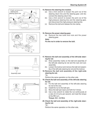
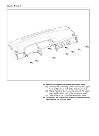
board rotary balancers, providing a convenience of use
and dynamic (double) balances. Unlike the on-board bal-
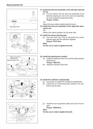
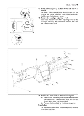
ance, they cannot correct the brake drum or brake disc
for imbalance, but they can overcome this shortcoming
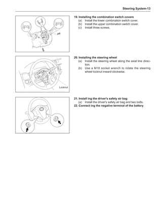
through their accuracy.
On-Board Balance
The on-board balance depends on the equipment and
tool manufacturer. Therefore, be sure to follow the in-
structions of various manufacturers to perform balance
operations.
Note:
Control the wheel rotative speed within 55 km /h
as shown in the speedometer. This restriction is
necessary because when a drive wheel is slipping
and the other drive wheel is static, the speedometer
only shows half of the actual wheel speed. Be care-
ful when the wheel is slipping because the slipping
wheel can reach a very high speed. This can cause
tire peeling off or damage to differentials, and cause
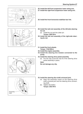
serious personal injuries or serious damage to cars.
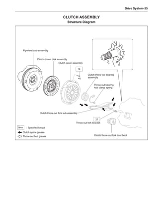
1
3
2
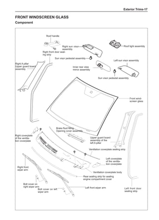
[A] [B]
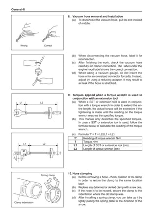
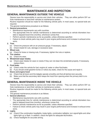
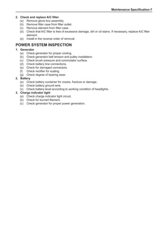
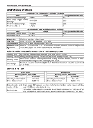
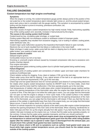
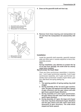
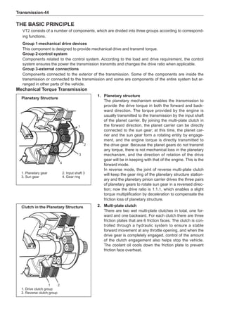
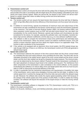
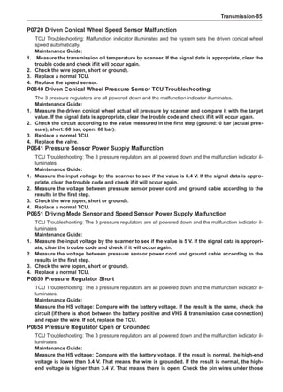
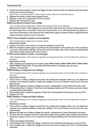
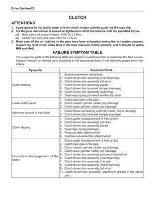
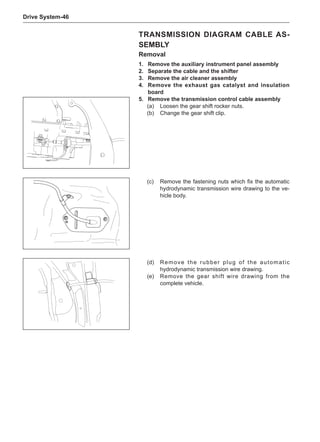
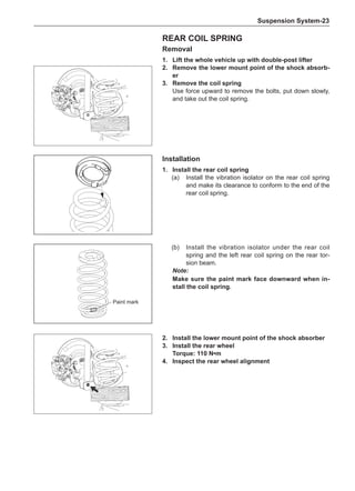
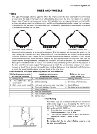
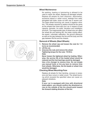
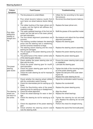
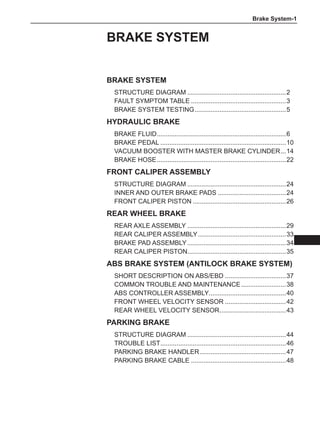
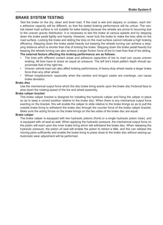
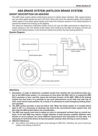
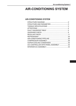
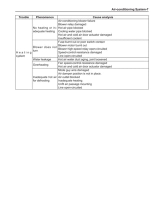
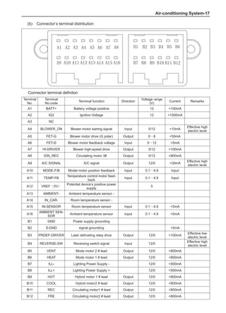
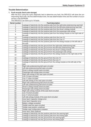
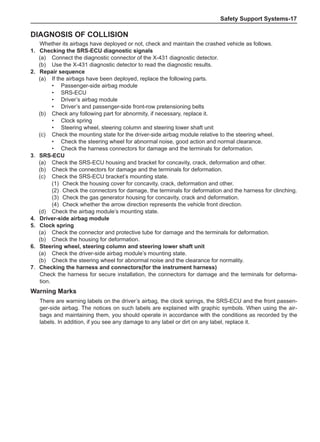
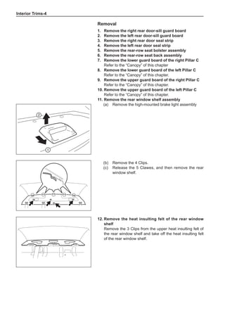
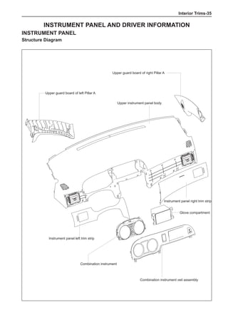
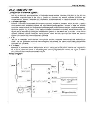
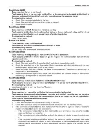
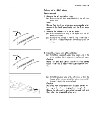
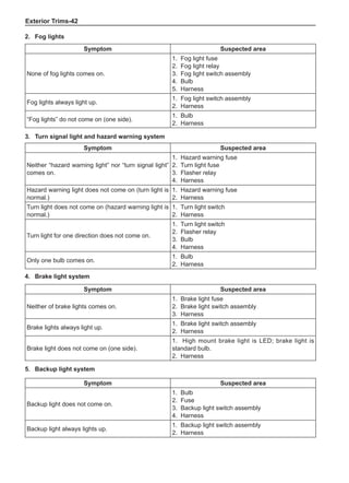
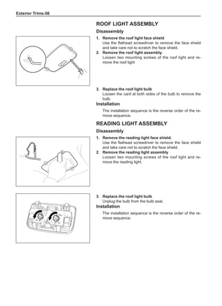
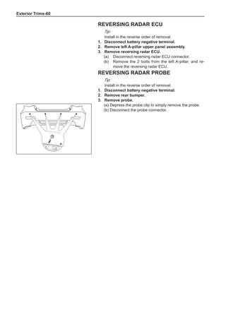
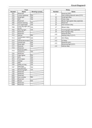
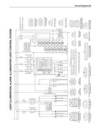
Chart 1
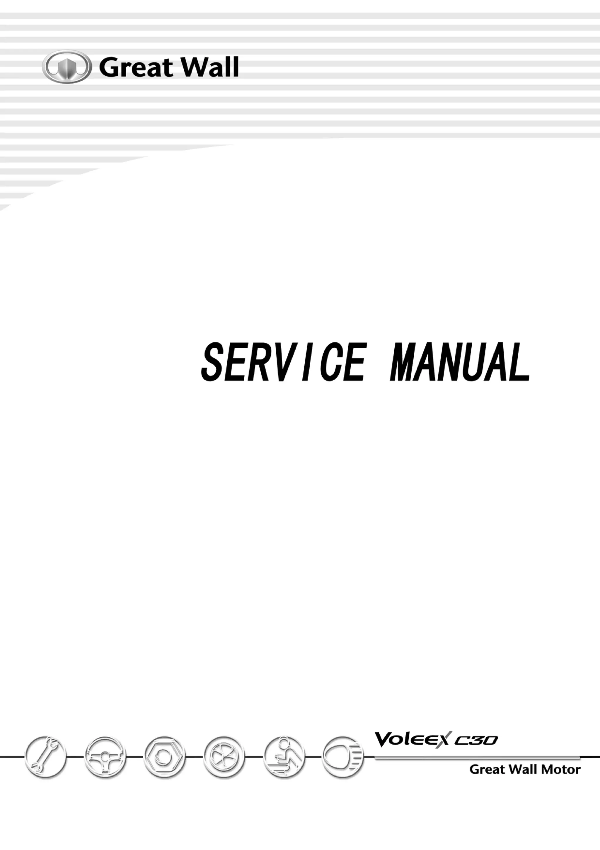
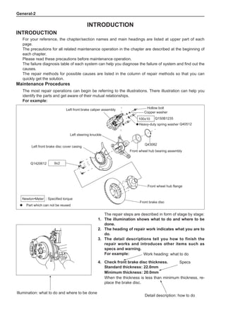
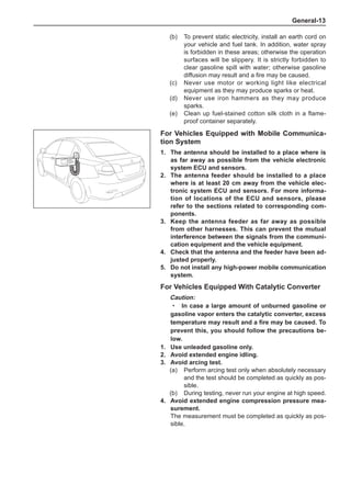
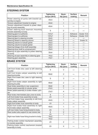
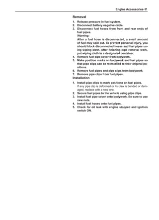
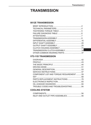
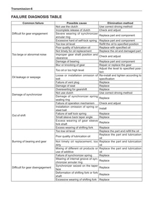
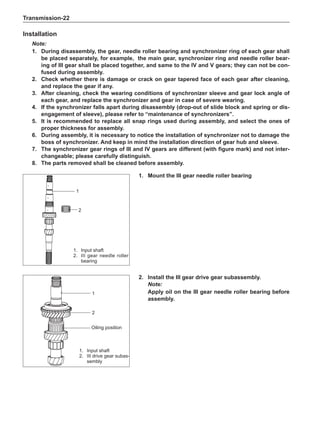
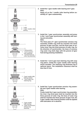
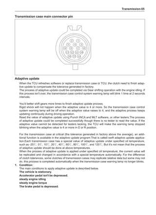
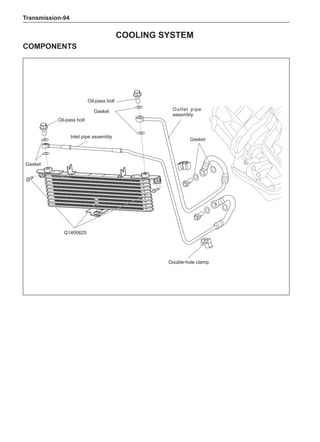
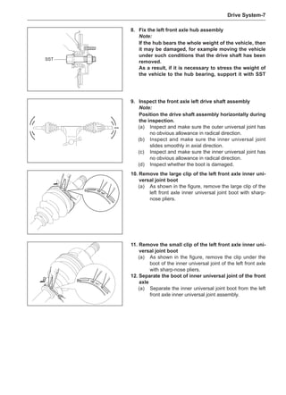
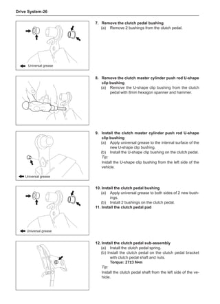
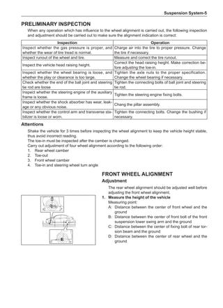
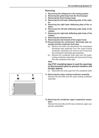
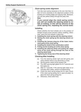
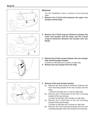
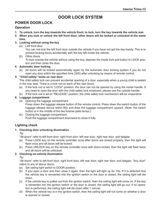
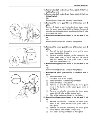
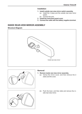
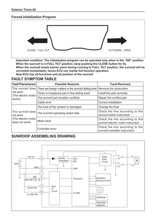
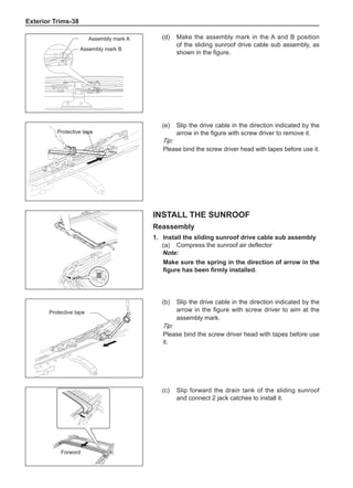
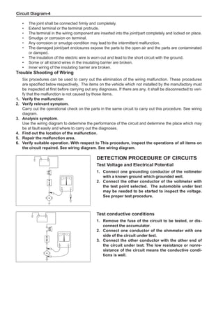
Dynamic Balance and Static Balance
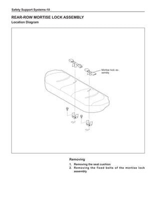
There are two types of wheel balance: static and dy-
namic. Chart 1 represents the static balance and Chart
2 represents the dynamic balance. The static balance
refers to the weight distribution around the wheel are
equal. The wheel imbalance in respect of the static bal-
ance can cause intense bouncing up and down. This is
called the bouncing vibration. This eventually can cause
uneven tire wear, as shown in Chart 1.
1. Wheel bouncing points [A]: without balance blocks
2. Points with balance blocks [B]: With balance blocks
3. Axle center](https://image.slidesharecdn.com/voleexc30servicemanual-220527123416-8120316f/85/VOLEEX-C30-service-manual-pdf-248-320.jpg)
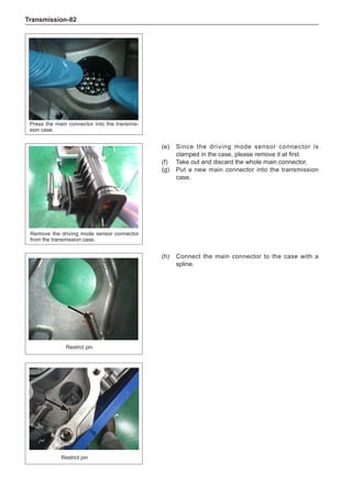
![Suspension System-33
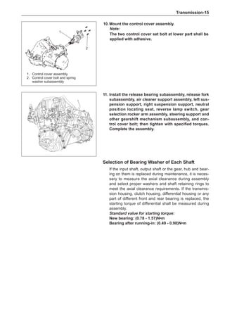
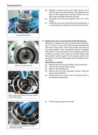
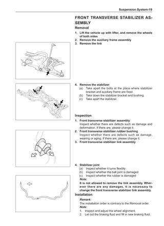
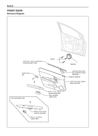
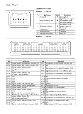
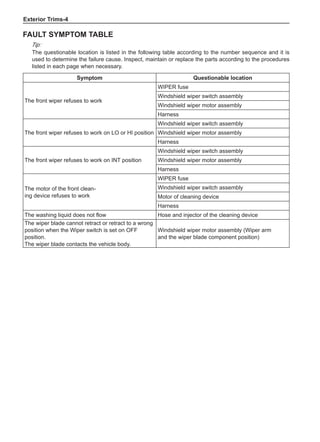
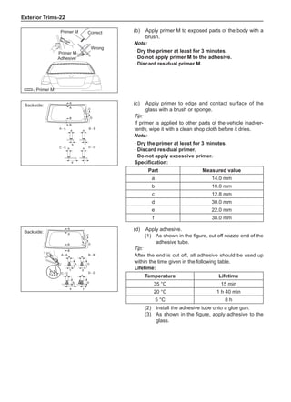
The Test Methods for Wheel Dynamic Balance
Are As Follows:
1. Clean the wheel to be tested, removing the dirt, sand
and stone and remove the old balance block.
2. Inflate the tire to match the specified pressure.
3. Install the wheel to the dynamic balancer and lock it
securely.
4. Turn on the power supply switch and check the indi-
cating device for correct indication.
5. Key in the rim diameter and the rim width, measure
the distance from the rim flange to the machine box
and key it in.
6. Put down the shield, press down the starting key and
start to measure.
7. After the wheel stopping rotating automatically, read
the dynamic imbalance masses and positions inside
and outside the wheel from the indicating device.
8. Rotate the wheel manually at a slow speed. When
the indicating device of the dynamic balancer sends
signals, stop rotating the wheel.
9. Place the dynamic imbalance masses shown by the
dynamic balancer onto the upper of the rim flange
according to the inside and outside positions and
clamp them securely.
10. Re-start the dynamic balancer to perform the dynam-
ic balance test until the dynamic imbalance weight is
less than 5g and the machine shows it is qualified.
11. Remove the wheel and turn off the power supply, and
this means the completion of the test. The operating
methods for using various dynamic balancer models
and brands are different so it is necessary to read
the relevant manuals before using.
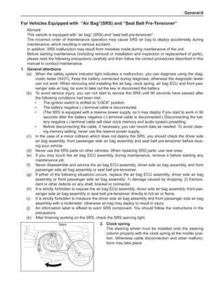
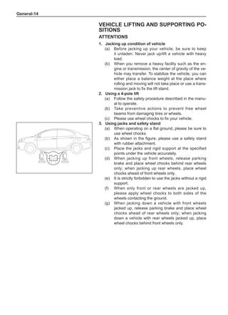
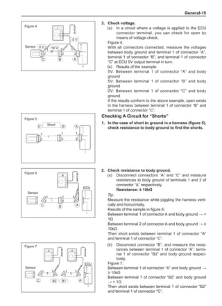
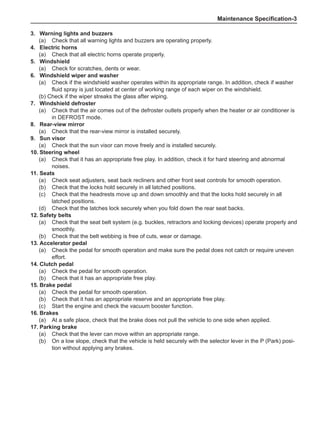
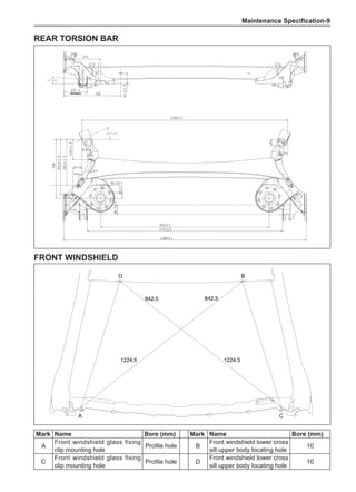
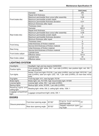
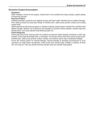
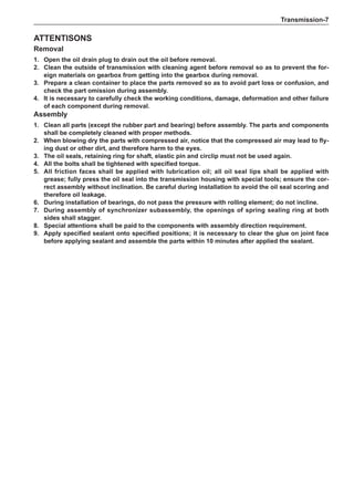
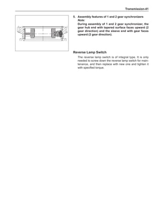
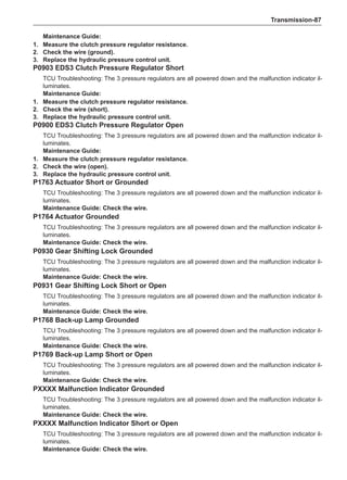
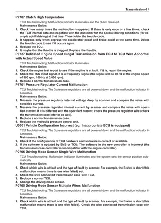
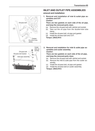
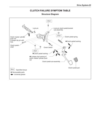
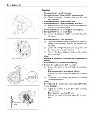
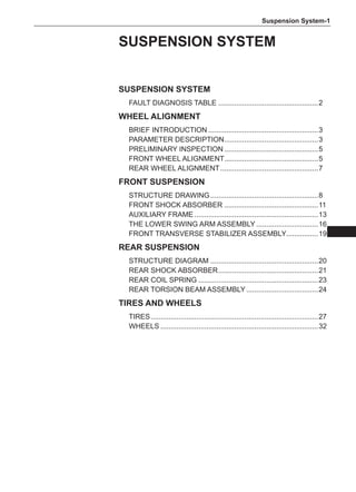
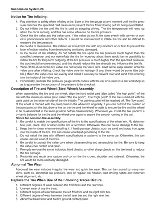
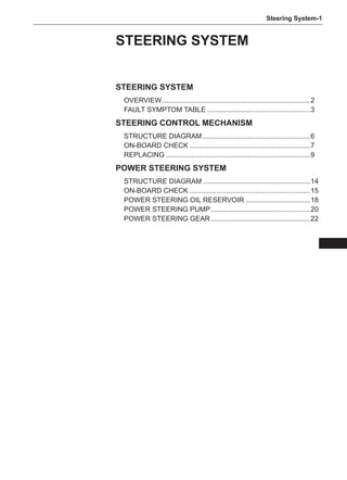
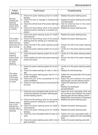
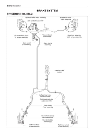
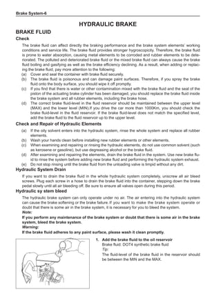
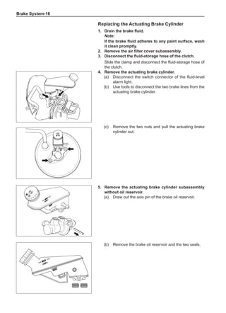
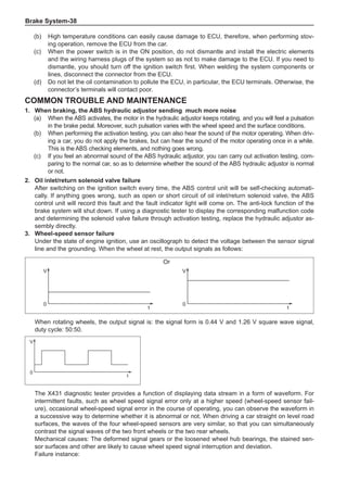
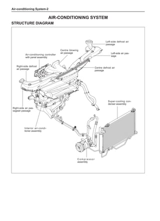
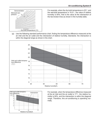
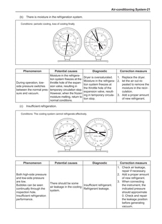
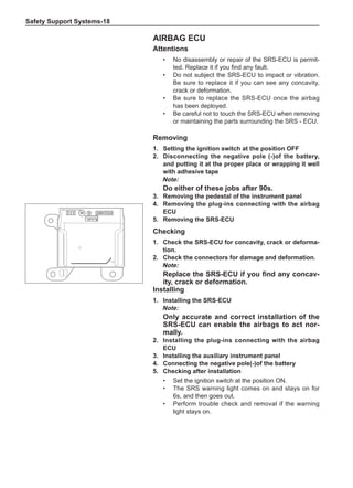
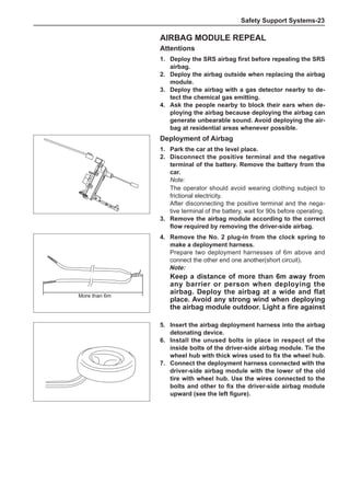
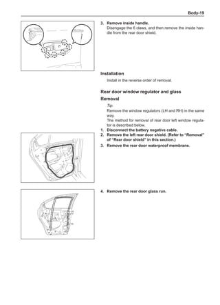
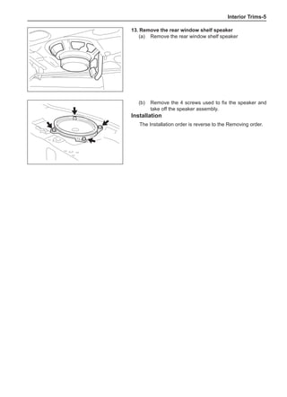
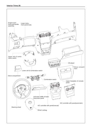
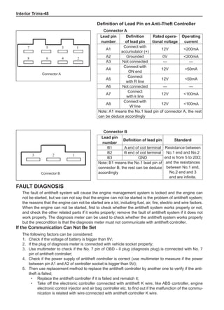
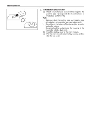
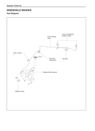
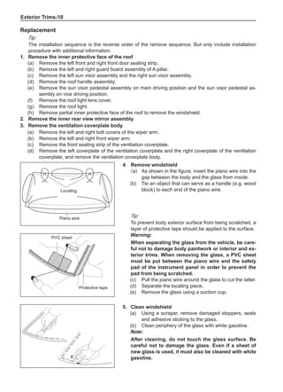
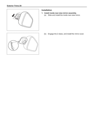
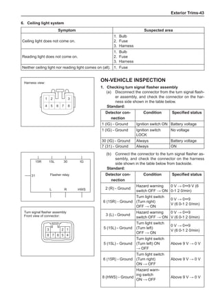
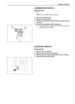
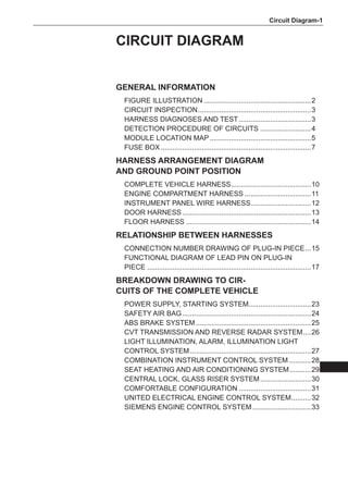
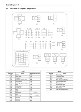
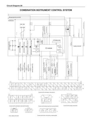
[C] [D]
1
3
2
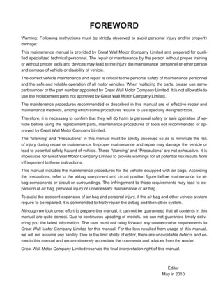
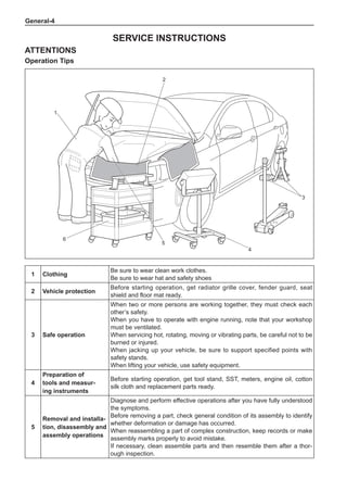
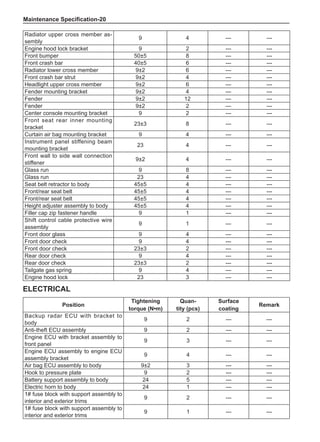
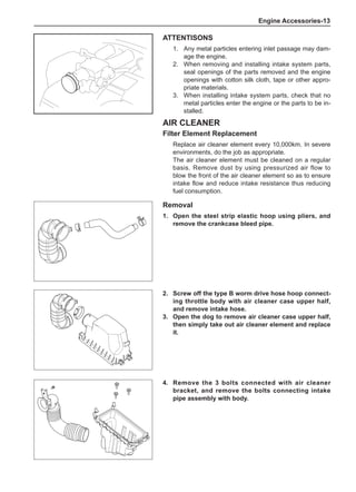
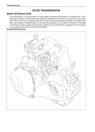
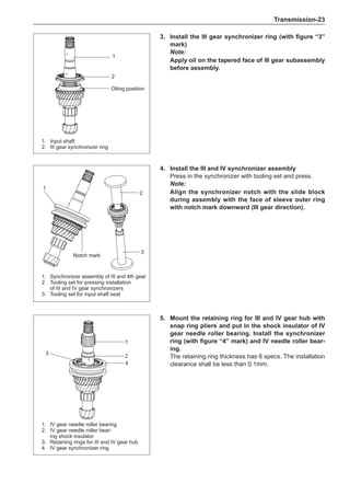
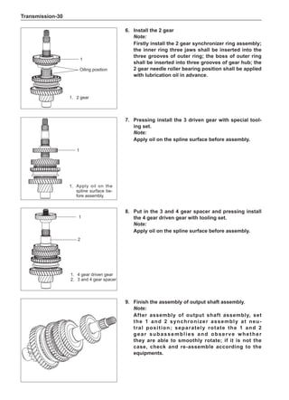
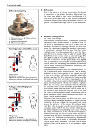
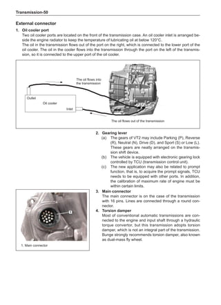
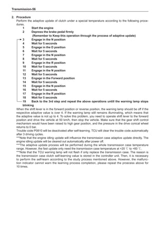
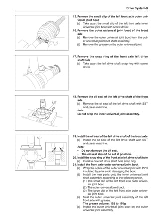
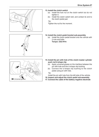
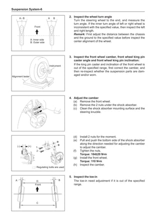
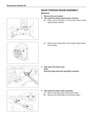
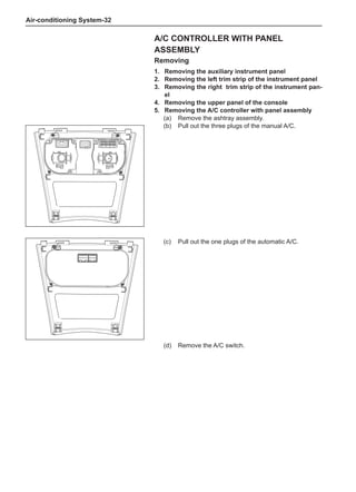
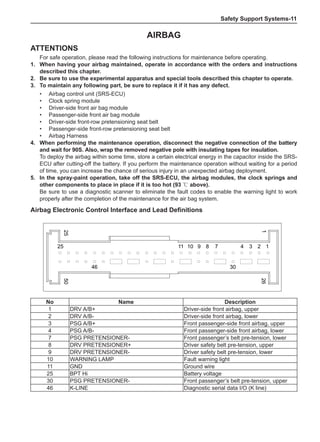
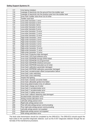
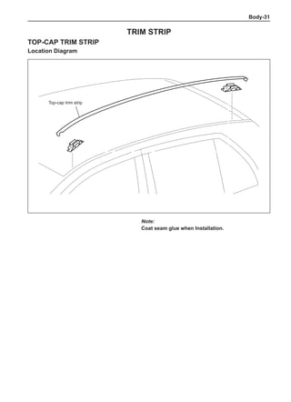
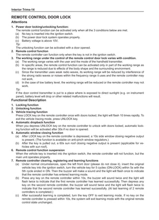
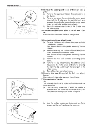
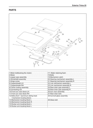
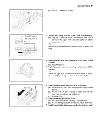
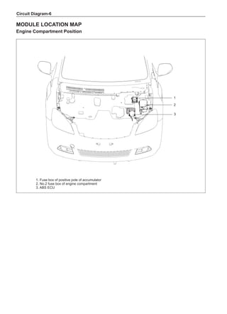
The dynamic balance refers to the weight distribution on
both sides of the wheel center plane are equal so that
the assembly will not tend to move from one side of the
center plane to the other side in the process of the tire
rotation. The wheel imbalance in respect of the dynamic
balance can cause oscillating, as shown in Chart 2.
1. Wheel oscillating points [C]: without balance blocks
2. Points with balance blocks [D]: With balance blocks
3. Axle center
Chart 2](https://image.slidesharecdn.com/voleexc30servicemanual-220527123416-8120316f/85/VOLEEX-C30-service-manual-pdf-249-320.jpg)


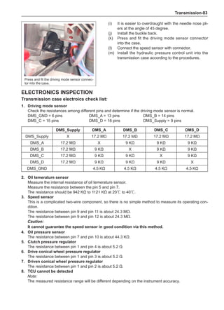
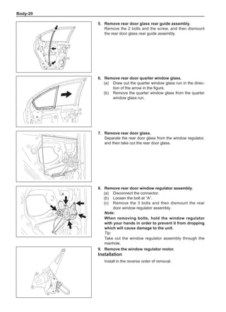
![Air-conditioning System-
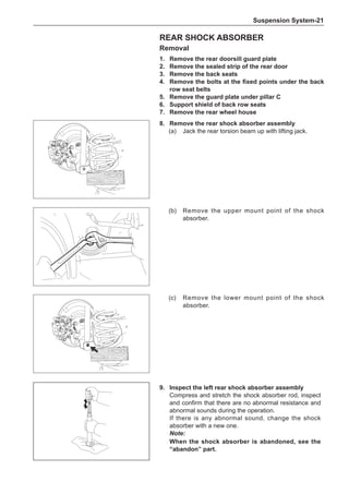
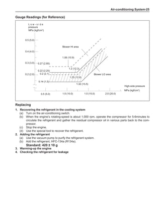
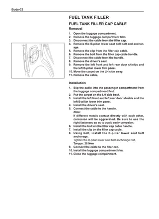
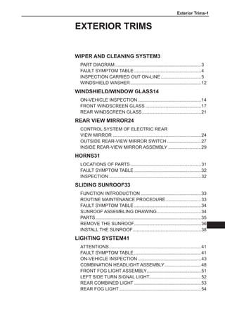
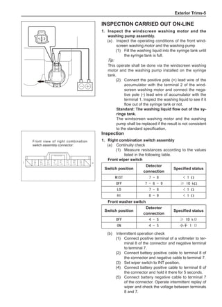
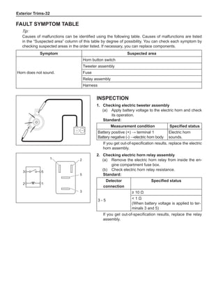
On-board check
1. Air-conditioning function check
(a) Install high-pressure measurement meter.
(b) Set the car to be in the following states.
Item Condition
Car Car parking in shade
Door Fully open
Air conditioning switch Switch on
Engine rotating-speed 2,000 rpm
Damper position of intake mode selector Outer recirculation
Outlet damper position Face
Set temperature Coldest
Blower speed HI
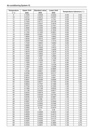
Air inlet temperature * 2 25 to 30ºC
Condenser pressure (high-pressure measurement meter) * 3 1.5 MPa
Tip:
*2 Make a correct determination as long as the air inlet temperature is maintained between 25 ℃ and
35 ℃. If the temperature is below 25 ℃, defer this test.
*3 When the condenser pressure (high-side measurement meter) is higher than 1.5 MPa, it is neces-
sary to spray or pour the condenser with water to reduce the pressure. When the condenser pres-
sure is too low, it is necessary to cover the front side of the condenser to increase the pressure.
(c) Place the dry/wet bulb thermometer at the air inlet and insert the bulb of the dry-bulb thermometer
into the center position of the air outlet.
(d) Operate the air-conditioning after the step [* 1], and keep the air outlet temperature stable (for
about 5-6 minutes).
(e) Measure the wet-bulb temperature at the air inlet and measure the dry-bulb temperature at the air outlet.
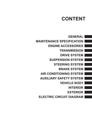
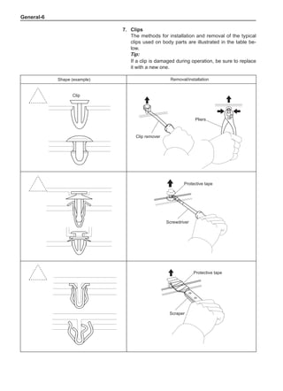
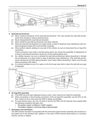
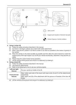
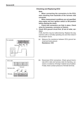
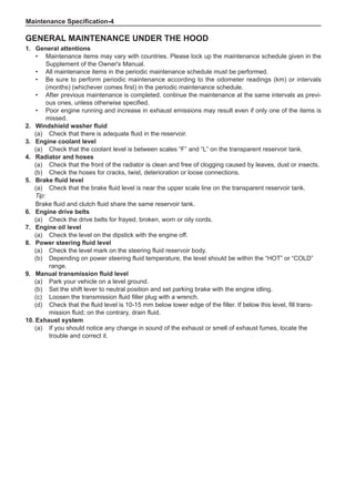
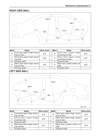
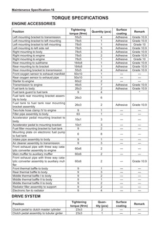
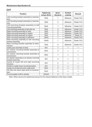
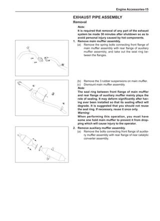
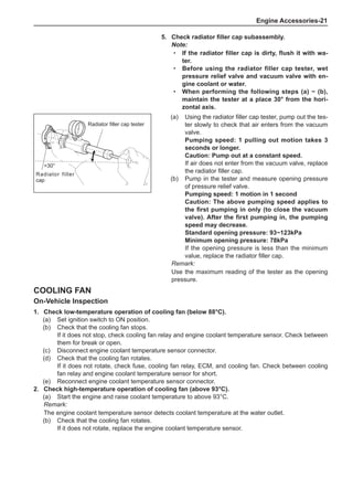
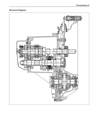
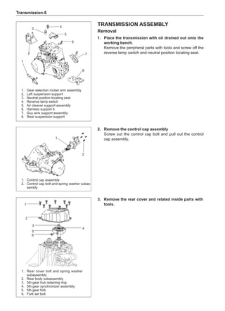
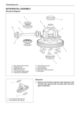
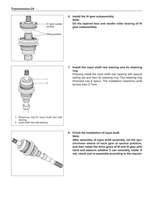
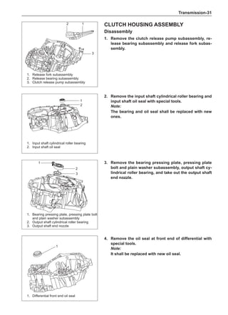
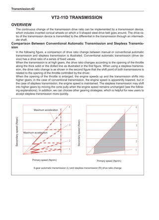
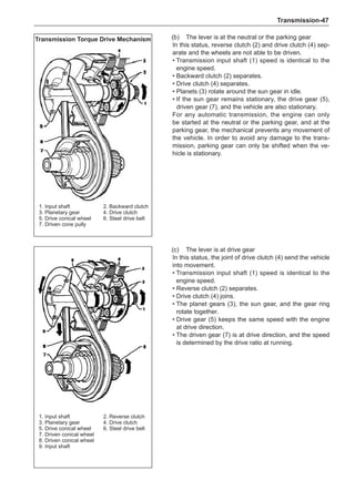
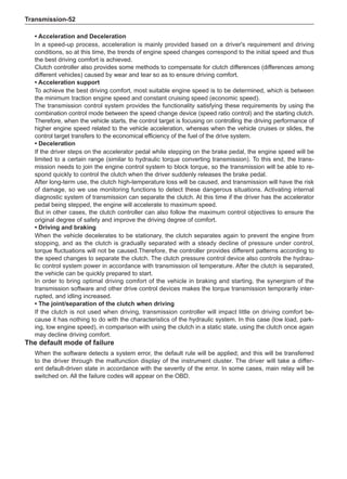
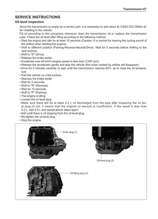
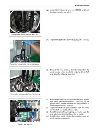
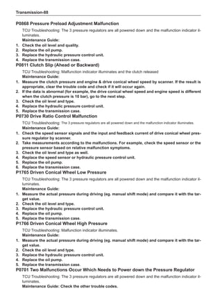
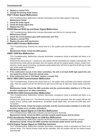
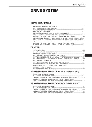
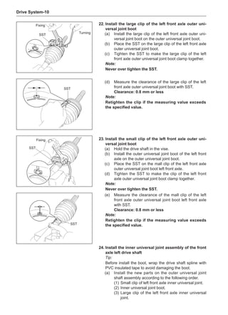
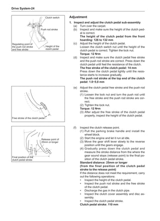
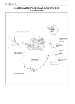
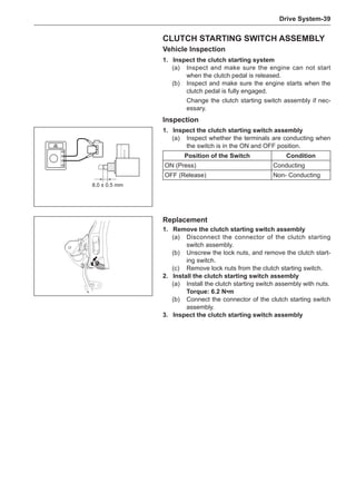
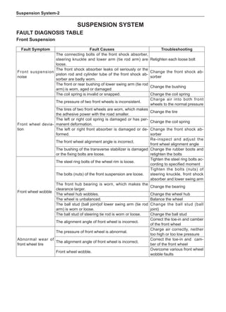
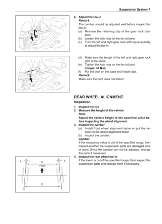
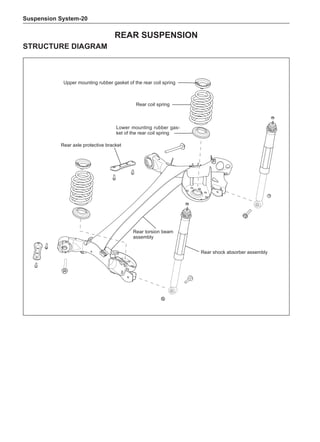
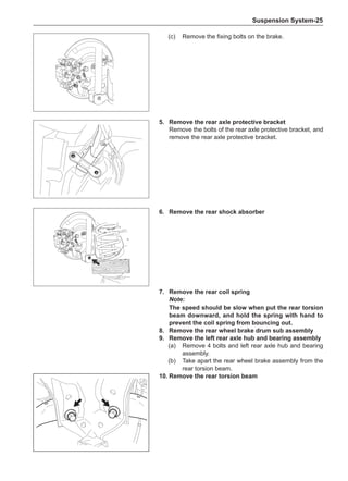
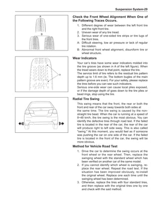
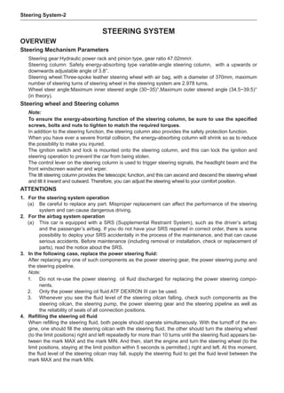
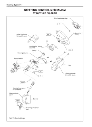
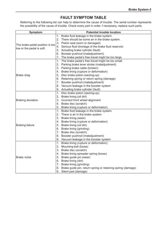
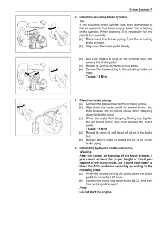
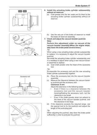
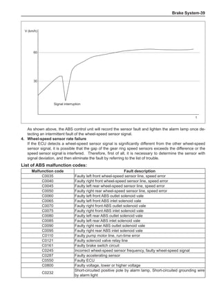
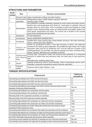
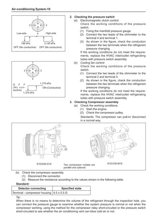
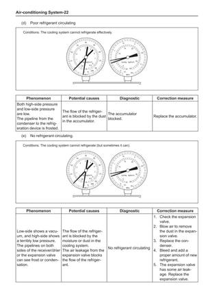
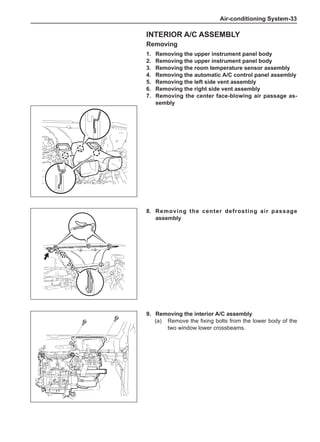
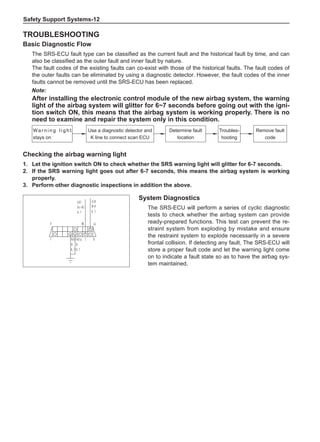
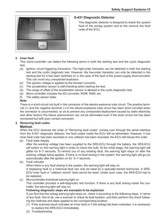
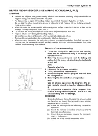
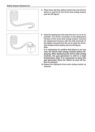
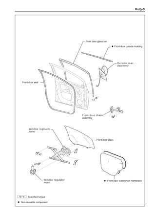
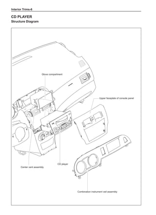
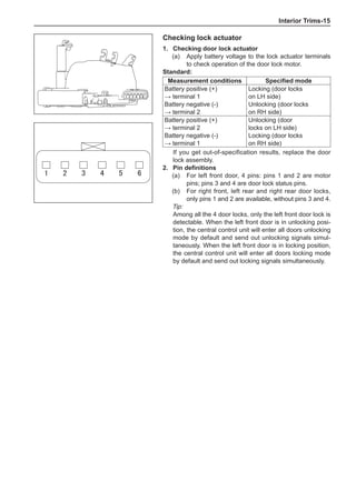
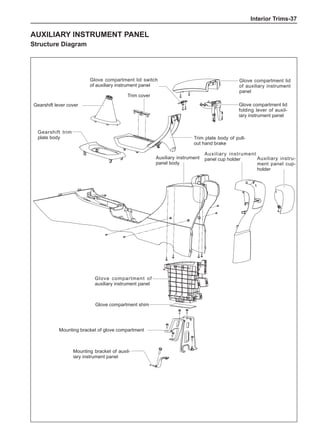
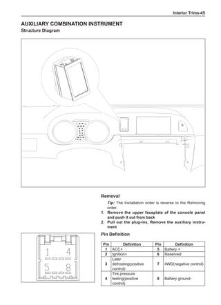
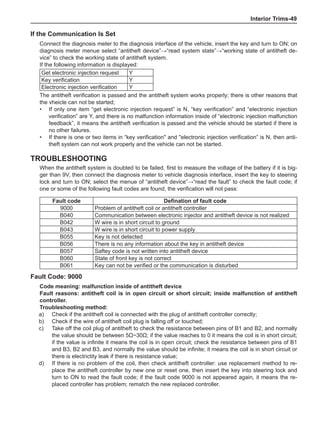
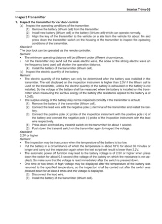
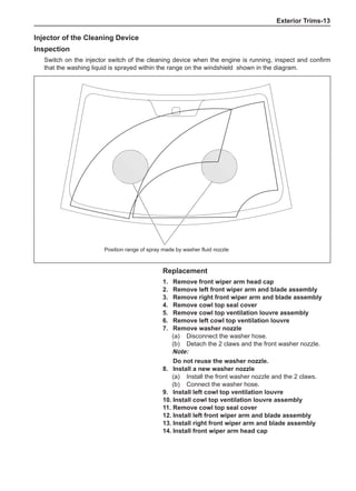
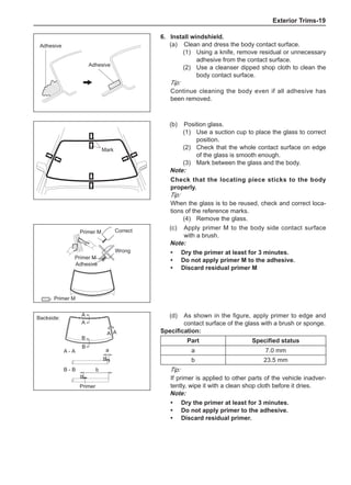
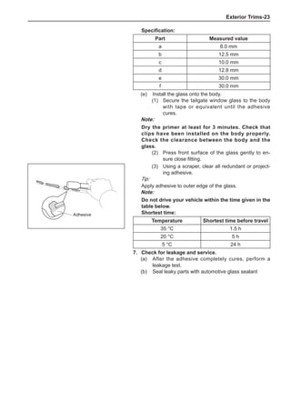
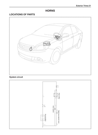
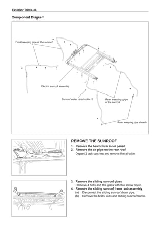
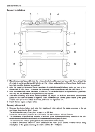
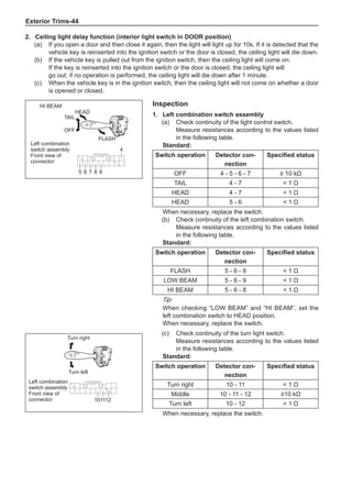
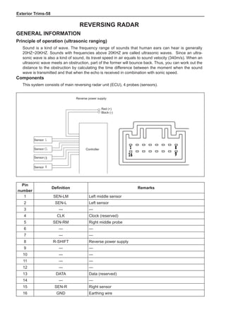
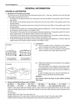
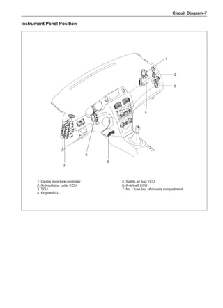
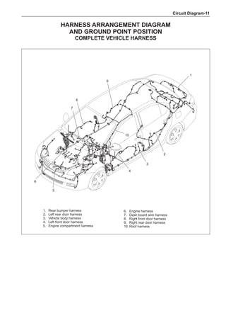
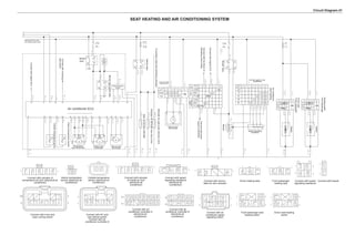
(f) Using the following humidity table, determine the value of relative humidity according to the mea-
sured value by the dry/wet bulb thermometer at the air inlet.
0
-5 -4 -3 -2 -1 0 1 2 3 4 5 6 7 8 9 10 11 12 13 14 15 16 17 1819 20 21 22 23 24 25 26 27 28 29 30 31 32 33 34 35 36 37 38 39 40
5
100
100%
90
9
0
80
8
0
70
7
0
60
60
50
50
40
40
30
30
20
20
10
10
10
15
20
25
30
Relative humidity
Dry bulb temperature (℃)
Wet bulb temperature
Relative humidity](https://image.slidesharecdn.com/voleexc30servicemanual-220527123416-8120316f/85/VOLEEX-C30-service-manual-pdf-336-320.jpg)


This document provides instructions and warnings for maintaining a vehicle that is equipped with airbags and seat belt pre-tensioners. It states that the incorrect order of maintenance can cause accidental deployment of airbags, which can result in serious injury. It provides guidelines for working with airbag components, including waiting 90 seconds after disabling the vehicle before working, not disassembling airbag parts, and storing airbag parts properly. The document emphasizes handling airbag parts carefully and following all provided precautions to avoid accidental deployment.


