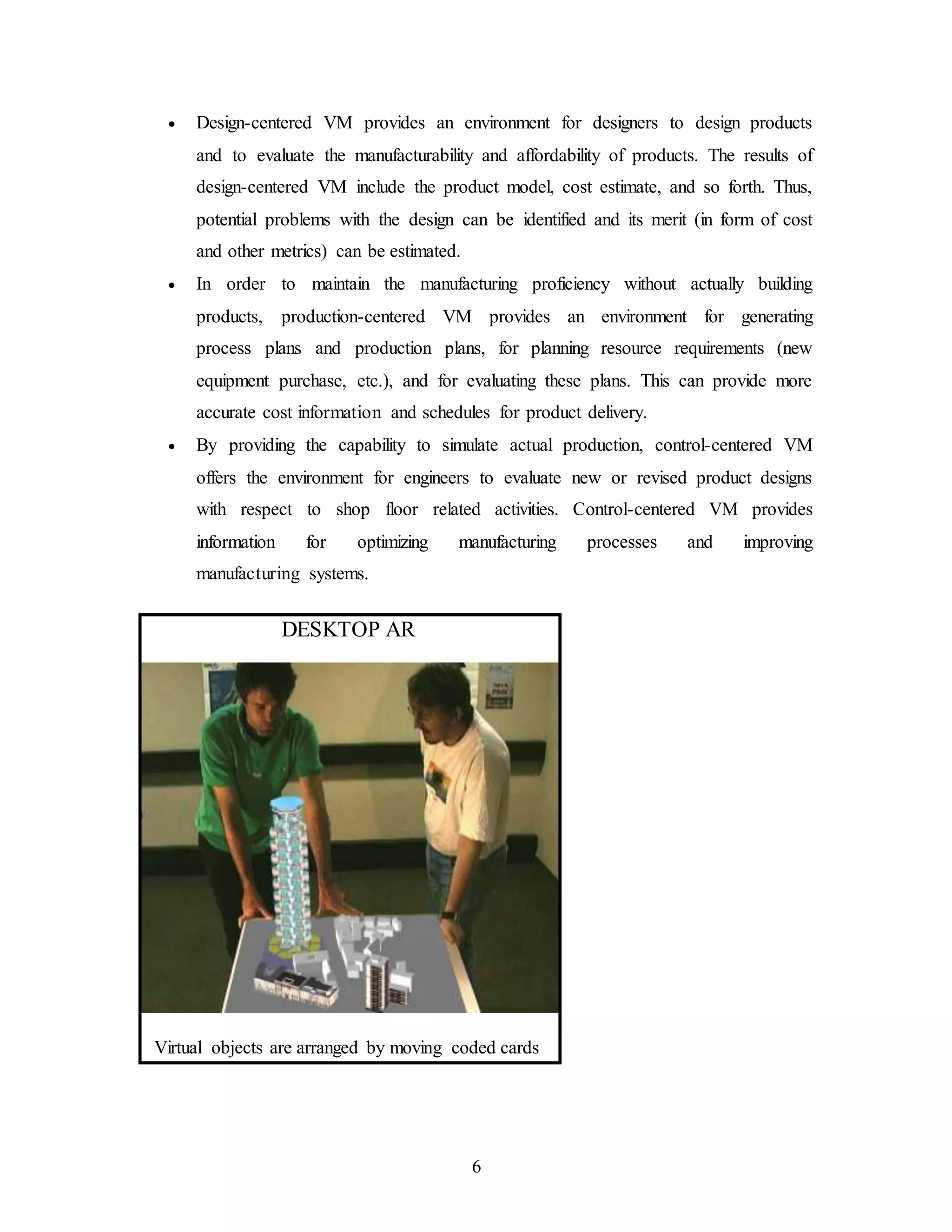
SlideShare a Scribd company logo
1 of 29
1
1. INTRODUCTION
Manufacturing is defined as the making of articles in an industry.
Manufacturing is the heart and soul of an industry. For an industry to excel in its field,
the company must possess the latest technology in manufacturing. One such technology
is “Virtual Manufacturing”.
Drawbacks of the conventional manufacturing systems
In conventional manufacturing, there is lots of time and money wasted on
building the physical prototypes of the manufacturing processes to be used before the
actual production starts. This takes a lot of time which can be used to optimize the
product design and market the product in a better way. There is also lots of money and
material wastage if more physical prototypes are required. With increasing competition in
today’s world, the conventional way of setting up production processes causes the
company a fortune. It was time for an innovation and this is how Virtual Manufacturing
was born.
The first step toward successfully launching the VM initiative was taken at a
Users Workshop on VM, held in Dayton on 12-13 July 1994. The workshop was held to
ensure that the needs and directions of those involved in and responsible for defense
manufacturing are accommodated in the VM initiative.
Before defining virtual manufacturing lets define Virtual Reality.
What is Virtual Reality?
Virtual Reality (VR) is an exciting new technology for which the most
important benefits are the ability to do human-in-the-loop, real time, "what if" scenarios,
reducing development time and reducing time to deliver products to the market. Virtual
reality promises a ready ability to interact in three dimensional space. In particular it is
possible to provide a visual simulation of familiar real-world environments, and to make
changes within such an environment.
2
VIRTUAL REALITY SYSTEM
COMPUTERISED VIRTUAL REALITY
Virtual Environment
Computer
Person
Input devices:
Head/eye/hand tracking
Output devices:
Graphics, Sound, Tactile
Shape, Colour, Patterns,
Textures, Lighting,
Viewpoints,
Behaviours…
Network
3
Augmented Reality in Manufacturing
Augmented Reality (AR) augments a user’s view of the world with computer
data and/or graphics models, which brings information into the user’s real world rather
than pulling the user into the computer’s virtual world. It is a more natural means of
exhibit a design in its real-world context.
VIRTUAL REALITY EXPERIENCE
What is Virtual Manufacturing?
Perhaps one of the most interesting and important of these recent
developments is called “Virtual Manufacturing”. Often termed “The Next Revolution in
Global Manufacturing”, virtual manufacturing involves the simulation of a product and
the processes involved in fabrication. Virtual Manufacturing (VM) is defined to be an
integrated, synthetic manufacturing environment exercised to enhance all levels of
decision and control. In simple words, the vision of Virtual Manufacturing is to provide a
capability to “Manufacture in the Computer”. Virtual Manufacturing (VM) is defined to
be an integrated, synthetic manufacturing environment exercised to enhance all levels of
decision and control.
4
In essence, VM will ultimately provide a modeling and simulation
environment so powerful that the fabrication/assembly of any product, including the
associated manufacturing processes, can be simulated in the computer. This powerful
capability would take into account all of the variables in the production environment
from shop floor processes to enterprise transactions. In other words, VM will
accommodate the visualization of interacting production processes, process planning,
scheduling, assembly planning, logistics from the line to the enterprise, and related
impacting processes such as accounting, purchasing and management. In addition, VM
also reduces the cost of tooling, eliminates the need for multiple physical prototypes, and
reduces material waste. This allows everyone to “get it right the first time”.
VM utilizes nonlinear finite element analysis technologies to provide
detailed information about a product, which is than used for optimization of factors such
5
as manufacturability, final shape, residual stress and life-cycle estimations. At the core of
VM lies nonlinear FEA technology.
A virtual part in a machining center. One can use such concept to effectively
debug and verify a process planning.
Three Paradigms of Virtual Manufacturing
Three major paradigms have been proposed for VM:
Design-Centered VM, Production-Centered VM and Control-Centered VM.
Figure 1 depicts the relationships among these three types of VM with respect to the
virtual product life-cycle. In this figure, the three blocks represent the three types of VM;
the relevant interactions (or information flow) are represented by directed arcs. For
example, the information (such as product models) provided by Design-centered VM to
Production-centered VM, is represented by a directed arc from the Design-centered VM
block to the Production-centered VM block.
These three different types of VM have the following characteristics:
6
 Design-centered VM provides an environment for designers to design products
and to evaluate the manufacturability and affordability of products. The results of
design-centered VM include the product model, cost estimate, and so forth. Thus,
potential problems with the design can be identified and its merit (in form of cost
and other metrics) can be estimated.
 In order to maintain the manufacturing proficiency without actually building
products, production-centered VM provides an environment for generating
process plans and production plans, for planning resource requirements (new
equipment purchase, etc.), and for evaluating these plans. This can provide more
accurate cost information and schedules for product delivery.
 By providing the capability to simulate actual production, control-centered VM
offers the environment for engineers to evaluate new or revised product designs
with respect to shop floor related activities. Control-centered VM provides
information for optimizing manufacturing processes and improving
manufacturing systems.
DESKTOP AR
Virtual objects are arranged by moving coded cards
7
THE MULTI-MEDIA HARD HAT, 1995
Concept for imposing the Augmented model on top of the real surroundings
8
2. FINITE ELEMENT ANALYSIS
Finite Element Analysis is a very powerful engineering design tool that
enables engineers and designers to simulate structural behavior, make design changes,
and see the effects of these changes. The finite element method works by breaking the
geometry of a real object down into a large number (1000’s or 100,000’s) of elements
(e.g. cubes). These elements form the mesh and the connecting points are the nodes. The
behavior of each little element, which is regular in shape, is readily predicted by set
mathematical equations. The summation of the individual element behavior produces the
expected behavior of the actual object. The mesh contains the material and structural
properties that define how the part reacts to certain load conditions. In essence, FEA is a
numerical method used to solve a variety of engineering problems that involve stress
analysis, heat transfer, electromagnetism, and fluid flow. FEA is in effect a computer
simulation of the whole process in which a physical prototype is built and tested, and then
rebuilt and retested until an acceptable design is created. Nonlinear FEA uses an
incremental solution procedure to step through the analysis. In contrast to linear FEA,
where a solution is achieved in one step, nonlinear FEA may require hundreds, even
thousands of steps.
There are three major types of nonlinearities:-
Material – plasticity, creep, viscoelasticity, Geometric – large deformations,
large strains, snap-through buckling, Boundary – contact, friction, gaps, follower force. A
nonlinear analysis can include any combination of these. In the case studies to follow,
you will encounter examples including all of these solution types.
9
3. STRUCTURE OF VIRTUAL
MANUFACTURING PROCESS
Each VM process is an ordered collection of individual steps called virtual
manufacturing operations (VMO). Each VMO changes the attributes of the starting
virtual work part, and requires a combination of a virtual machine tool and virtual
tooling. The VMO is essentially a set of physics-based process models derived from first
principles. Different VMO’s could be constructed based on different principles, i.e., a
virtual machining operation, a virtual assembly operation, a virtual inspection operation,
etc. The virtual machining operation is defined as a set of physics-based analytical and
numerical models that describe the phenomena of chip formation zone including the
mechanics and thermodynamics of the process, tribology, and tool wear. The virtual
machining operation, as part of the virtual manufacturing process, communicates with the
other objects in the immediate vicinity of the VM system (the virtual machine tool,
virtual prototyping system, and virtual inspection system) by exchanging information as
shown in Figure 2.
The virtual machining operation interfaces with the VP system. When the VP
system interacts with the VMO as in Figure 2, it provides VMO with information about
the geometrical and material specifications of the work part. In return, the VMO will send
back to the VP system information about the manufacturability of the prototype.
10
Additional information may be exchanged between VP and VMO to enhance design and
manufacturing functions, which would in essence emulate the Design Manufacturability
related activities. Also, VP will interact with the other objects in the virtual
manufacturing, for example the virtual machining tool and virtual inspection system, to
provide and receive information on the various aspects involved. Another object of the
subsystem illustrated in figure 2 is the virtual machine tool. A virtual machine tool is a
computer- based subsystem of the VM system exercised to improve the machine tool
characteristics like dimensional accuracy, productivity, and machining performance. The
virtual machining operation provides the virtual machine tool with information about the
cutting forces and temperatures required to calculate the elastic and temperature
deformations. In return, the VMO receives input on the machining parameters, tool
geometry and materials, and the spatial positions of the virtual work part and cutting tool.
Additional information may be exchanged between virtual machine tool and virtual
machining operation to enhance machining functions and machine functionalities.
The virtual inspection system is an object that is created based on the real
inspection units used in the manufacturing process. For example, the virtual inspection
station will have a virtual coordinate measuring machine with virtual probes and a virtual
fixture to hold the virtual work part. The virtual inspection unit contains metrology model
that simulates the working principle of the measuring device, like the CMM machine,
optical comparator, etc., kinematic models to simulate the working of the machine, error
generation models, and calibration models which are exercised to measure the virtual
work part. Just like the other system elements, the virtual inspection unit communicates
with the other objects. It receives information about the real geometry of the virtual work
part as calculated by superimposing the ideal geometry provided by the VP system with
the error envelope created during the VMO and checks the work part geometry for
compliance with the geometrical tolerances. The information generated by the virtual
inspection unit is then fed back to the virtual machine tool and the virtual machining
operation to compensate for the error or change the machining conditions to ensure that
the work part produced is within design specifications. In addition, the virtual inspection
system may incorporate a quality module to facilitate the statistical process control.
11
Illustrative example – A simple orthogonal machining process has been
developed to illustrate the virtual machining operation concept. It consists of a heat-
transfer model, a two-dimensional model of the mechanics of chip formation, and a
cutting tool wear model. These three models take the input values for various parameters
like tool geometry, tool material properties, cutting conditions, and work material
properties from the virtual prototyping system and the virtual machine tool. The model
provides feedback to the virtual inspection system and the virtual prototyping system
through the dimensional error calculator explained elsewhere. For the purpose of this
work, the heat-transfer model and the mechanics of chip formation model have been
developed in a non-linear hybrid finite element/analytical formulation.
The analytical model of the chip formation produces data for velocities,
stresses, and strain rates in selected points in the chip formation zone. This information is
then entered into the finite element model (FEM) to calculate the temperature fields in the
work, tool, and chip. The FEM has an adaptive re-meshing to account for the change in
the geometry. The elemental temperatures generated by FEM are then used to update the
material properties in the chip formation model. The hybrid model accounts for important
features of the process such as frictional conditions at the tool-chip interface, the change
in material properties with temperature, strain, and strain-rate. It is fully predictive and
requires data only for the mechanical and thermal properties and tool materials as well as
cutting conditions and tool geometry from the virtual prototyping system and the virtual
machine tool. The volumetric tool wear model is comprised of a set of analytical models
of the principle wear mechanisms acting in metal cutting - diffusion, adhesion, and
abrasion.
The outcomes of the wear model are the volumetric tool wear and the width of
wear land (VB) defined as the cutting time required for the cutting tool to develop a flank
wear land of width VB, the so-called wear criterion.
12
4. CASE STUDY: IMACS
(INTERACTIVE MANUFACTURABILITY ANALYSIS AND
CRITIQUING SYSTEM)
The ability to quickly introduce new quality products is a decisive factor in
capturing market share. Because of pressing demands to reduce lead time, analyzing the
manufacturability of the proposed design has become an important step in the design
stage. As shown below, the IMACS project is extending the design loop to incorporate a
manufacturability analysis system that can be used once the geometry and/or tolerances
have been specified. This will help in creating designs that not only satisfy the functional
requirements but are also easy to manufacture.
We assume that the proposed design is available as a solid model, along with
the tolerance and surface finish information as attributes of various faces of the solid
model. We assume we have information about the available machining operations,
including the process capabilities, dimensional constraints, etc. As shown on the next
page, our approach is to generate alternative interpretations of the part as collections of
machining features, map these interpretations into operation plans, and evaluate the
manufacturability of each operation plans. The ultimate goal of the IMACS project is to
provide tools for manufacturability analysis as part of the CAD systems used by
designers. We believe our work will help designers design products that are easier to
manufacture. This will reduce the need for redesign, resulting in reduced lead time and
13
product cost. In addition, it will help to speed up the evaluation of new product designs in
order to decide how or whether to manufacture them. Such a capability will be especially
useful in flexible manufacturing systems, which need to respond quickly to changing
demands and opportunities in the marketplace.
Manufacturability Analysis
Given a computerized representation of the design (i.e. a solid model) and a
set of manufacturing resources, the automated manufacturability analysis problem can be
defined as follows:
1. Determine whether or not the design attributes (e.g., shape, dimensions,
tolerances, surface finishes) can be achieved.
2. If the design is found to be manufacturable, determine a manufacturability rating,
to reflect the ease (or difficulty) with which the design can be manufactured.
14
3. If the design is not manufacturable, then identify the design attributes that pose
manufacturability problems.
In general, a design's manufacturability is a measure of the effort required to
manufacture the part according to the design specifications. Our approach to measuring
manufacturability is to estimate the manufacturing time and cost. Since all manufacturing
operations have measurable time and cost, these can be used as an underlying basis to
form a suitable manufacturability rating. Ratings based on time and cost can easily be
combined into a overall rating. Moreover, they present a realistic view of the difficulty in
manufacturing a proposed design and can be used to aid management in making make-or-
buy decisions.
In a machining operation, a cutting tool is swept along a trajectory, and
material is removed by the motion of the tool relative to the current workpiece. The
volume resulting from a machining operation is called a machining feature.
More specifically, their approach involves the following steps :-
1. Build the set of all potential machining features by identifying various features
which can be used to create the part from the stock. Each of these features represents a
different possible machining operation which can be used to create various surfaces of
the part.
2. Repeat following steps until every promising feature-based model (FBM) has been
examined :-
A. Generate a promising FBM from the feature set. An FBM is a set of
machining features that contains no redundant features and is sufficient to create the
part. We consider an FBM unpromising if it is not expected to result in any operation
plans better than the ones which have already been examined.
B. Do the following steps repeatedly, until every promising operation plan
resulting from the particular FBM has been examined :-
i) Generate a promising operation plan for the FBM. This operation plan
represents a partially ordered set of machining operations. We consider an operation plan
to be unpromising if it violates any common machining practices.
ii) Estimate the achievable machining accuracy of the operation plan. If the
operation plan cannot produce the required design tolerances and surface finishes, then
15
discard it and go to Step 1.
iii) Estimate the production time and cost associated with operation plan.
3. If no promising operation plans were found, then exit with failure. Otherwise exit
with success, returning the operation plan that represents the best tradeoff among quality,
cost, and time.
Analysis of SocketDesign:
16
Manufacturing Processes-
Machinable by drilling and end-milling operations.
The best plan requires 13 operations in 3 different setups.
Total time required to machine the socket :- 31.13 minutes.
IMACS's output includes an optimal operation plan for the design.
As shown below, this plan includes three setups:-
(Blue colour indicates-that face of the workpiece is being machined first)
Setup 1:
Setup 2:
Setup 3:
17
5. VIRTUAL MANUFACTURING OPTIMIZES
ROLL FORMING PROCESS
PROBLEM
Cold formed roll profiles are important structural elements in almost any area
of engineering. This includes automotive, and construction, where a large variety of open
or closed section bar shaped profiles are used. In the continuous roll forming process, flat
sheet metal is formed by driving pairs of contoured rolls into a finished profile through
several stages without any intended reduction in sheet thickness. The final profile shape
can be influenced by longitudinal strains causing sheet edge waviness and bowing. Also,
residual stresses in the profile produce spring-back, and can deform the final profile
shape. In order to speed up tool design, virtual manufacturing based techniques are
required to aid in planning of the pass sequence development, calculation of the spring-
back angle, and estimation of the strip edge elongation.
SOLUTION
The planning for a new part begins with a definition of the finished section, the
design of the pass sequences, and the sizing of the different rolls in the CAD system. In
this analysis, the CAD data was fed into the MSC.Marc FEA solver, and the simulation
was run. The results were analyzed to determine the deviations in shape and dimensions
of the finished section. The longitudinal strains of the sheet edge revealed the quality of
the roll forming process. Some of the characteristics that were checked included,
dimensional tolerances, angular tolerances, longitudinal bow, twist sheet edge waviness,
and profile end deformation. After optimizing the manufacturing process in this virtual
environment, the manufacturer was able to manufacture the tools and run a test in the
mill. This analysis avoids high costs derived from improperly designed tools needing
adjustment and rework in the mill to fit a new profile.
18
6. SIDE IMPACT ANALYSIS OF A CAR DOOR
REDUCES INJURIES
PROBLEM
In car accidents, side impacts result in numerous injuries because the side
structure of the car, including the occupant compartment, is crushed. During design, the
strength of the door should be stressed for passenger safety. It is a common belief that
improvements in the strength of the door itself is quite effective for passenger safety,
particularly in collisions from the oblique direction, or with fixed objects. In this
research, MSC.Marc was used for static compression analysis and dynamic impact
analysis to understand the crash worthiness of the door. Experiments were also performed
for comparison purposes. In addition, the effectiveness of the door-beams, which were
installed within the doors, were analyzed.
SOLUTION
The doors used for this experiment were the front doors of four door sedans.
The door panels, hinges, locks, and other necessary mechanisms were used, while the
windows and door trims were removed. Hinges and latches were constrained. For static
compression and dynamic impact, the loading device was applied laterally on the center
19
of the door. Experimental results of a door in the body show different characteristics from
the results of a door alone, mainly because the door contacts with the center pillar and
side sill; therefore, the force on the door is distributed rather than concentrated on the
latch. However, the latch part still receives most of the force. In fact, experimental results
of the door within the car body showed cracks in the latch part, just like the results with
the door alone. The importance of the strength of the latch part should be stressed for the
strength of the door itself. From the static compression analysis and dynamic impact
analysis of a door, as well as the experiments, it was found that the strength of the door
hinge and door latch strongly affected the crush resistance of a door itself. In the
experiments, it was found that once crack propagation occurred in the latch, the force
drastically decreased. It was also necessary to consider reinforcing the latch even when a
door has a door-beam. It was also found that by attaching a door-beam, absorption of the
deformation energy increased and deformation of the door decreased upon impact.
20
7. PLANNING A PLANT USING VIRTUAL
MANUFACTURING
Only a decade ago, it took many years for a spacecraft to move from the
drawing board to the launch pad. It now takes only about two years to design and build a
satellite, thanks to recent advances in computer-aided design and other technological
techniques. It used to take five to seven years before a new model car was ready for
market. Today, that cycle has been shortened to two or three years. And time to market
continues to drop, even as the size and the complexity of satellites and automobiles grow.
Still, market pressures are pushing manufacturers for even more reductions in time to
market. VM allows manufacturers to simulate factory layout digitally, in order to see how
the plant would function under the proposed arrangement and to predict out potential
problems on the line.
With VM, engineers are able to design individual assembly-line
workstations via computer for smooth functioning and to guard workers
against repetitive-motion injuries.
Contrary to what it may sound like, digitizing the factory, as it's sometimes
called, doesn't mean replacing all the workers in a plant with high-tech robots. Instead,
the software can help ensure that a product is manufactured in the most streamlined
method possible. CAD tools help engineers take care to come up with optimal product
21
design. But VM makes sure the product can be manufactured in the right quality with
reliable processes, within the shortest time frame, and with the best factory layout.
Digital factory software is used for more than just laying out a plant floor on
computer. It serves a number of functions around the manufacturing plant, including
designing individual workstations in order to guard employees against repetitive motion
injuries. VM lets manufacturing engineers visualize the production process via
computer—which allows an overview of factory operations for a particular
manufacturing job.
There are three areas to consider before actually laying out a real factory.
First, engineers have to determine the assemblies, fabrication, and machining needed for
the specific manufacturing process. Second, they need to figure out what tooling, fixtures,
and equipment—down to the nuts and bolts—will be needed. Then, they must lay out a
factory floor plan. VM is useful for each of these steps. Virtual factory software allowed
engineers to test how operators, tools, and material-handling systems would work
together even before construction began. If engineers decide to change the design of a
part while the part is still only a CAD model, they can use VM to demonstrate the effect
of the new design at every stage of the manufacturing process. The redesigned part, for
example, might need more clearance on the automotive line.
The same software that engineers use to simulate plant functioning via
computer can also be used to program and site robots on the assembly
22
VM also allows engineers to simulate robotic functioning. We can see
whether the robots can reach all the points it needs to reach. With the help of VM we can
decide for each robot where it should stand.
In addition to robots, employees themselves can be represented in a digitized
version. In this way, engineers can figure out where employees should stand on the line
and design workstations for them to both optimize their movements and to ensure they're
not under any kind of ergonomic stress. Using VM, engineers can tell if an employee
could reach a particular tool on the line and if the employee would be strong enough to
lift it. They can see whether an employee could repeatedly perform a task without risking
a repetitive-motion injury.
It used to take five to seven years from design to manufacture to create a
new car model. Factory simulation software has helped cut that time in half.
One of the major providers of software for virtual manufacturing applications
is the Delmia Corp. of Troy, Michigan. Other software and hardware providers in this
realm are Tecnomatix Technologies of Herzeliya, Israel; Rockwell Automation of
Milwaukee, and EDS of Plano, Texas.
DaimlerChrysler of Stuttgart, Germany, is currently digitizing the way its
manufacturing plants are designed. Factories will be entirely simulated—inside and out,
from initial floor plans to functioning assembly lines—before they're built. The key is
that the investment is expected to reduce new-vehicle production cycles by up to 30
percent, an automaker's holy grail. VM is becoming a leading tool in industries today.
23
8. RELIABILITY OF COST, SCHEDULE AND
QUALITY ESTIMATES MADE USING VM
Reliability of an estimated value of a criterion (such as cost, schedule, or
quality) is defined as the closeness of that estimate to the average value of the criterion
resulting from actual manufacturing.
The manual (or semi-manual) estimation techniques described above require a
detailed description of the design, and knowledge of the processes to be used in
production. Since they are based on empirical knowledge, which has been derived from
years of experience, they typically provide reliable estimates for both the cost and the
processing time.
Manufacturability-related studies have automated the design critiquing
process to a certain extend. The product and process information used in such studies
may vary greatly in detail. Some methods assess the manufacturability based on
information that is known at the initial design stages. Other methods require a fully
developed design. As discussed above, however, most studies use indirect metrics for
design critiquing, which quantify the relative and not the absolute difficulty of
manufacture. Thus, it is difficult to assess the reliability of the manufacturability
estimates. Even these methods that do estimate processing times, do not account for the
dynamics of the production system, and therefore they cannot estimate the product's lead
(or cycle) time which contains queuing time. (Note that the latter may range from 50 to
95% of the cycle time). Similarly, although it may be possible to estimate material and
labor costs, it is not feasible to estimate inventory costs without considering the dynamics
of the production system. Finally, the ability to estimate product quality is minimal since
there manufacturability studies do not generally use sophisticated process models.
Virtual manufacturing is able to provide accurate estimates for processing
times, cycle times and costs (including inventory), as well as product quality. This is
because VM can model both the processes employed for the product's manufacture and
the production system dynamics. By employing comprehensive models of manufacturing
processes, VM will be able to accurately predict set-up times and run times, and,
consequently, labor costs. Furthermore, if these process models are able to predict the
24
variance of key product attributes, then process yields or the values of quality ratios may
be obtained by comparing the process capability with the corresponding design
tolerances. On the other hand, modeling the production process will yield queue times, as
well as Work-In-Process and finished goods inventory. Consequently, accurate estimates
of overall cycle times and overall costs may be obtained. The potential of VM to provide
accurate cost, lead time and quality estimates is a major motivation to use this tool.
25
9. ADVANTAGES
FEWER PROTOTYPES – The more trials you can simulate in a virtual environment,
the less physical prototypes you need to perfect your design. This means you spend more
time up front in engineering and design, and less resources running physical trials.
Virtual prototyping is cheaper than building physical models and optimizing your design
by trial-and-error. It is not complete replacement for physical testing, but it can minimize
the effort and enable the resulting physical tests to be more successful.
LESS MATERIAL WASTE – If you build fewer physical models, you waste less
material in the form of prototypes as well as the tooling used to create them.
REDUCED COST OF TOOLING – Again it follows that if you build fewer
prototypes, then you develop fewer tools, which are typically very expensive.
Furthermore, by modeling the tools, you can reduce tool wear, thus increasing tool life.
CONFIDENCE IN MANUFACTURING PROCESS – Even if the tools are
properly designed, the control of the tools may affect the quality of the part produced.
VM allows you to simulate the part, the tools, and their control. This simulation can let
you optimize your tool control before building prototypes, again letting you “get it right
the first time”.
IMPROVED QUALITY – It improves their part quality by utilizing VM techniques.
There are numerous examples throughout this paper, and almost all of them result in a
part with quality produced at lower cost than previously attained through traditional
prototyping techniques.
REDUCED TIME TO MARKET – Time to market is becoming increasingly
critical in an age where information can be transmitted and shared readily. Although VM
may translate into spending more resources in the design and engineering phases, the
26
resulting product will need much less rework downstream. This saves enormously in
unforeseen redesign and re-engineering efforts.
LOWER OVERALL MANUFACTURING COST – The bottom line is that our
customers have had success incorporating VM techniques into their processes, and none
have gone back to the traditional product design cycle. We are confident that you will
also share in this success.
27
10. CONCLUSION
Virtual manufacturing, when mature, is expected to greatly support assessing
the manufacturability of a candidate design and to provide accurate estimates for
processing times, cycle times and costs (including inventory), as well as product quality.
This is because VM will be able to model both the processes employed for the product's
manufacture and the production process. By employing comprehensive models of
manufacturing processes, VM will be able to accurately predict set-up times and run
times, and, consequently, labor costs. Furthermore, if these process models are able to
predict the variance of key product attributes, then process yields or the values of quality
ratios may be obtained by comparing the process capability with the corresponding
design tolerances. On the other hand, modeling the production process will yield queue
times, as well as Work-In-Process and finished goods inventory. Consequently, accurate
estimates of overall cycle times and overall costs may be obtained. Tools that assess
manufacturability by generating and evaluating manufacturing plans require more
computing time than approaches that try to analyze the design directly, but they also offer
more accurate results. As the cost of computing power continues to decrease, we
anticipate that such approaches will become increasingly widespread.
The potential of VM to support manufacturability assessments and provide
accurate cost, lead time and quality estimates is a major motivation for further research
and development in this area. There are several advancements, however, that are needed
to effectively support manufacturability assessments using virtual manufacturing. These
include:
1) Support for computer-aided conceptual design.
2) Integration beyond single applications and single manufacturing domains.
3) Critical role in supporting generative and hybrid approaches to process
planning.
4) Necessity to develop methods for integrating product design and process
planning with production planning and scheduling.
28
5) Need to develop product information models that are able to shape
information and data that are directly relevant to manufacturing, such as
tolerances (dimensional and geometric), and form features.
6) Need to integrate process models into concurrent engineering and VM
systems.
7) New information models are necessary to capture the capabilities and
performance of production systems, and thus provide plant-specific
information to the virtual manufacturing system for design evaluation.
The development of an all inclusive virtual manufacturing system is a science itself, and
this paper is only a humble attempt in this direction.
29
11. REFERENCES
BOOK REFERENCE
1. Vijay Ramachandran, 1995, "Information Models for Agile Manufacturing,"
Master's Thesis, University of Maryland at College Park.
2. David W. Rosen, John R. Dixon, Corrado Poli, and Xin Dong. Features and
algorithms for tooling cost evaluation in injection molding and die casting. In
Proceedings of the ASME International Computers in Engineering Conference ,
pages 1-8. ASME, 1992.
3. Achieving agile manufacturing in the automotive industry: Part I. Automotive
Engineering, 102(11):19, November 1994.
4. Achieving agile manufacturing in the automotive industry: Part II. Automotive
Engineering, 102(12):13, December 1994.
5. Douglas L. Waco and Yong Se Kim. Geometric reasoning for machining features
using convex decomposition. Computer Aided Design, 26(6):477--489, June
1994.
WEB REFERENCES
1. www.howstuffworks.com
2. www.virtualmanufacturing.com
3. www.mscsoftware.com
4. www.wiley.com

More Related Content

Similar to virtual-manufacturing.doc

Development Prototype Design of Virtual Assembly Application-Based Leap Motion
Development Prototype Design of Virtual Assembly Application-Based Leap MotionDevelopment Prototype Design of Virtual Assembly Application-Based Leap Motion
Development Prototype Design of Virtual Assembly Application-Based Leap MotionIJAEMSJORNAL
 
CAD and VIRTUAL REALITY
CAD  and VIRTUAL REALITYCAD  and VIRTUAL REALITY
CAD and VIRTUAL REALITYDeepak Rotti
 
Today, electronic work instructions soft-ware is instrumenta.docx
Today, electronic work instructions soft-ware is instrumenta.docxToday, electronic work instructions soft-ware is instrumenta.docx
Today, electronic work instructions soft-ware is instrumenta.docxedwardmarivel
 
Quasi-Static Evaluation of a Modular and Reconfigurable Manufacturing Cell
Quasi-Static Evaluation of a Modular and Reconfigurable Manufacturing CellQuasi-Static Evaluation of a Modular and Reconfigurable Manufacturing Cell
Quasi-Static Evaluation of a Modular and Reconfigurable Manufacturing CellHillary Green
 
digital twin seminar 1.pptx
digital twin seminar 1.pptxdigital twin seminar 1.pptx
digital twin seminar 1.pptxMacZain
 
IRJET- Role of Artificial Intelligence in Flexible Manufacturing Process - A ...
IRJET- Role of Artificial Intelligence in Flexible Manufacturing Process - A ...IRJET- Role of Artificial Intelligence in Flexible Manufacturing Process - A ...
IRJET- Role of Artificial Intelligence in Flexible Manufacturing Process - A ...IRJET Journal
 
Virtual manufacturing
Virtual manufacturing Virtual manufacturing
Virtual manufacturing jagannathps3
 
Digital Twin Driven Optimization of Human Cyber Physical Environment in Smart...
Digital Twin Driven Optimization of Human Cyber Physical Environment in Smart...Digital Twin Driven Optimization of Human Cyber Physical Environment in Smart...
Digital Twin Driven Optimization of Human Cyber Physical Environment in Smart...IRJET Journal
 
Integrated industry- Manufacturing of the Future
Integrated industry- Manufacturing of the FutureIntegrated industry- Manufacturing of the Future
Integrated industry- Manufacturing of the FutureWg Cdr Jayesh C S PAI
 
Prototyping of the Virtual Type
Prototyping of the Virtual TypePrototyping of the Virtual Type
Prototyping of the Virtual TypeDon Talend
 
Digital Twin Technology: Function, Significance, and Benefits
Digital Twin Technology: Function, Significance, and BenefitsDigital Twin Technology: Function, Significance, and Benefits
Digital Twin Technology: Function, Significance, and Benefitsemilybrown8019
 
SYSTEM AND RISK ANALYSIS OF CLOUDMANUFACTURING SYSTEM
SYSTEM AND RISK ANALYSIS OF CLOUDMANUFACTURING SYSTEMSYSTEM AND RISK ANALYSIS OF CLOUDMANUFACTURING SYSTEM
SYSTEM AND RISK ANALYSIS OF CLOUDMANUFACTURING SYSTEMIJCSES Journal
 
B Kindilien-The Digital Age of Manufacturing
B Kindilien-The Digital Age of ManufacturingB Kindilien-The Digital Age of Manufacturing
B Kindilien-The Digital Age of ManufacturingjgIpotiwon
 
Assignment 1 - Application of Simulation Software.pdf
Assignment 1 - Application of Simulation Software.pdfAssignment 1 - Application of Simulation Software.pdf
Assignment 1 - Application of Simulation Software.pdfSafeen Yaseen Ja'far
 
Conceptual framework for designing Intelligent factory
Conceptual framework for designing Intelligent factoryConceptual framework for designing Intelligent factory
Conceptual framework for designing Intelligent factoryTanmay Patil
 
What is Digital Twins?
What is Digital Twins?What is Digital Twins?
What is Digital Twins?Nickjohn33
 
Recent concept used in manufacturingVirtual Factory.pptx
Recent concept used in manufacturingVirtual Factory.pptxRecent concept used in manufacturingVirtual Factory.pptx
Recent concept used in manufacturingVirtual Factory.pptxcharanjitkaur58
 

Similar to virtual-manufacturing.doc (20)

Development Prototype Design of Virtual Assembly Application-Based Leap Motion
Development Prototype Design of Virtual Assembly Application-Based Leap MotionDevelopment Prototype Design of Virtual Assembly Application-Based Leap Motion
Development Prototype Design of Virtual Assembly Application-Based Leap Motion
 
CAD and VIRTUAL REALITY
CAD  and VIRTUAL REALITYCAD  and VIRTUAL REALITY
CAD and VIRTUAL REALITY
 
Virtual manufacturing
Virtual manufacturingVirtual manufacturing
Virtual manufacturing
 
Today, electronic work instructions soft-ware is instrumenta.docx
Today, electronic work instructions soft-ware is instrumenta.docxToday, electronic work instructions soft-ware is instrumenta.docx
Today, electronic work instructions soft-ware is instrumenta.docx
 
Quasi-Static Evaluation of a Modular and Reconfigurable Manufacturing Cell
Quasi-Static Evaluation of a Modular and Reconfigurable Manufacturing CellQuasi-Static Evaluation of a Modular and Reconfigurable Manufacturing Cell
Quasi-Static Evaluation of a Modular and Reconfigurable Manufacturing Cell
 
digital twin seminar 1.pptx
digital twin seminar 1.pptxdigital twin seminar 1.pptx
digital twin seminar 1.pptx
 
IRJET- Role of Artificial Intelligence in Flexible Manufacturing Process - A ...
IRJET- Role of Artificial Intelligence in Flexible Manufacturing Process - A ...IRJET- Role of Artificial Intelligence in Flexible Manufacturing Process - A ...
IRJET- Role of Artificial Intelligence in Flexible Manufacturing Process - A ...
 
Virtual manufacturing
Virtual manufacturing Virtual manufacturing
Virtual manufacturing
 
Digital Twin Driven Optimization of Human Cyber Physical Environment in Smart...
Digital Twin Driven Optimization of Human Cyber Physical Environment in Smart...Digital Twin Driven Optimization of Human Cyber Physical Environment in Smart...
Digital Twin Driven Optimization of Human Cyber Physical Environment in Smart...
 
Integrated industry- Manufacturing of the Future
Integrated industry- Manufacturing of the FutureIntegrated industry- Manufacturing of the Future
Integrated industry- Manufacturing of the Future
 
Prototyping of the Virtual Type
Prototyping of the Virtual TypePrototyping of the Virtual Type
Prototyping of the Virtual Type
 
Digital Twin Technology: Function, Significance, and Benefits
Digital Twin Technology: Function, Significance, and BenefitsDigital Twin Technology: Function, Significance, and Benefits
Digital Twin Technology: Function, Significance, and Benefits
 
SYSTEM AND RISK ANALYSIS OF CLOUDMANUFACTURING SYSTEM
SYSTEM AND RISK ANALYSIS OF CLOUDMANUFACTURING SYSTEMSYSTEM AND RISK ANALYSIS OF CLOUDMANUFACTURING SYSTEM
SYSTEM AND RISK ANALYSIS OF CLOUDMANUFACTURING SYSTEM
 
17.pdf
17.pdf17.pdf
17.pdf
 
B Kindilien-The Digital Age of Manufacturing
B Kindilien-The Digital Age of ManufacturingB Kindilien-The Digital Age of Manufacturing
B Kindilien-The Digital Age of Manufacturing
 
Assignment 1 - Application of Simulation Software.pdf
Assignment 1 - Application of Simulation Software.pdfAssignment 1 - Application of Simulation Software.pdf
Assignment 1 - Application of Simulation Software.pdf
 
Conceptual framework for designing Intelligent factory
Conceptual framework for designing Intelligent factoryConceptual framework for designing Intelligent factory
Conceptual framework for designing Intelligent factory
 
What is Digital Twins?
What is Digital Twins?What is Digital Twins?
What is Digital Twins?
 
Digital twin
Digital twinDigital twin
Digital twin
 
Recent concept used in manufacturingVirtual Factory.pptx
Recent concept used in manufacturingVirtual Factory.pptxRecent concept used in manufacturingVirtual Factory.pptx
Recent concept used in manufacturingVirtual Factory.pptx
 

Recently uploaded

High Profile Call Girls Nagpur Meera Call 7001035870 Meet With Nagpur Escorts
High Profile Call Girls Nagpur Meera Call 7001035870 Meet With Nagpur EscortsHigh Profile Call Girls Nagpur Meera Call 7001035870 Meet With Nagpur Escorts
High Profile Call Girls Nagpur Meera Call 7001035870 Meet With Nagpur EscortsCall Girls in Nagpur High Profile
 
result management system report for college project
result management system report for college projectresult management system report for college project
result management system report for college projectTonystark477637
 
Sheet Pile Wall Design and Construction: A Practical Guide for Civil Engineer...
Sheet Pile Wall Design and Construction: A Practical Guide for Civil Engineer...Sheet Pile Wall Design and Construction: A Practical Guide for Civil Engineer...
Sheet Pile Wall Design and Construction: A Practical Guide for Civil Engineer...Dr.Costas Sachpazis
 
Call for Papers - Educational Administration: Theory and Practice, E-ISSN: 21...
Call for Papers - Educational Administration: Theory and Practice, E-ISSN: 21...Call for Papers - Educational Administration: Theory and Practice, E-ISSN: 21...
Call for Papers - Educational Administration: Theory and Practice, E-ISSN: 21...Christo Ananth
 
High Profile Call Girls Nagpur Isha Call 7001035870 Meet With Nagpur Escorts
High Profile Call Girls Nagpur Isha Call 7001035870 Meet With Nagpur EscortsHigh Profile Call Girls Nagpur Isha Call 7001035870 Meet With Nagpur Escorts
High Profile Call Girls Nagpur Isha Call 7001035870 Meet With Nagpur Escortsranjana rawat
 
Call for Papers - African Journal of Biological Sciences, E-ISSN: 2663-2187, ...
Call for Papers - African Journal of Biological Sciences, E-ISSN: 2663-2187, ...Call for Papers - African Journal of Biological Sciences, E-ISSN: 2663-2187, ...
Call for Papers - African Journal of Biological Sciences, E-ISSN: 2663-2187, ...Christo Ananth
 
Java Programming :Event Handling(Types of Events)
Java Programming :Event Handling(Types of Events)Java Programming :Event Handling(Types of Events)
Java Programming :Event Handling(Types of Events)simmis5
 
(RIA) Call Girls Bhosari ( 7001035870 ) HI-Fi Pune Escorts Service
(RIA) Call Girls Bhosari ( 7001035870 ) HI-Fi Pune Escorts Service(RIA) Call Girls Bhosari ( 7001035870 ) HI-Fi Pune Escorts Service
(RIA) Call Girls Bhosari ( 7001035870 ) HI-Fi Pune Escorts Serviceranjana rawat
 
(MEERA) Dapodi Call Girls Just Call 7001035870 [ Cash on Delivery ] Pune Escorts
(MEERA) Dapodi Call Girls Just Call 7001035870 [ Cash on Delivery ] Pune Escorts(MEERA) Dapodi Call Girls Just Call 7001035870 [ Cash on Delivery ] Pune Escorts
(MEERA) Dapodi Call Girls Just Call 7001035870 [ Cash on Delivery ] Pune Escortsranjana rawat
 
MANUFACTURING PROCESS-II UNIT-5 NC MACHINE TOOLS
MANUFACTURING PROCESS-II UNIT-5 NC MACHINE TOOLSMANUFACTURING PROCESS-II UNIT-5 NC MACHINE TOOLS
MANUFACTURING PROCESS-II UNIT-5 NC MACHINE TOOLSSIVASHANKAR N
 
Booking open Available Pune Call Girls Koregaon Park 6297143586 Call Hot Ind...
Booking open Available Pune Call Girls Koregaon Park  6297143586 Call Hot Ind...Booking open Available Pune Call Girls Koregaon Park  6297143586 Call Hot Ind...
Booking open Available Pune Call Girls Koregaon Park 6297143586 Call Hot Ind...Call Girls in Nagpur High Profile
 
KubeKraft presentation @CloudNativeHooghly
KubeKraft presentation @CloudNativeHooghlyKubeKraft presentation @CloudNativeHooghly
KubeKraft presentation @CloudNativeHooghlysanyuktamishra911
 
SPICE PARK APR2024 ( 6,793 SPICE Models )
SPICE PARK APR2024 ( 6,793 SPICE Models )SPICE PARK APR2024 ( 6,793 SPICE Models )
SPICE PARK APR2024 ( 6,793 SPICE Models )Tsuyoshi Horigome
 
MANUFACTURING PROCESS-II UNIT-2 LATHE MACHINE
MANUFACTURING PROCESS-II UNIT-2 LATHE MACHINEMANUFACTURING PROCESS-II UNIT-2 LATHE MACHINE
MANUFACTURING PROCESS-II UNIT-2 LATHE MACHINESIVASHANKAR N
 
Call Girls Pimpri Chinchwad Call Me 7737669865 Budget Friendly No Advance Boo...
Call Girls Pimpri Chinchwad Call Me 7737669865 Budget Friendly No Advance Boo...Call Girls Pimpri Chinchwad Call Me 7737669865 Budget Friendly No Advance Boo...
Call Girls Pimpri Chinchwad Call Me 7737669865 Budget Friendly No Advance Boo...roncy bisnoi
 
Porous Ceramics seminar and technical writing
Porous Ceramics seminar and technical writingPorous Ceramics seminar and technical writing
Porous Ceramics seminar and technical writingrakeshbaidya232001
 
(ANVI) Koregaon Park Call Girls Just Call 7001035870 [ Cash on Delivery ] Pun...
(ANVI) Koregaon Park Call Girls Just Call 7001035870 [ Cash on Delivery ] Pun...(ANVI) Koregaon Park Call Girls Just Call 7001035870 [ Cash on Delivery ] Pun...
(ANVI) Koregaon Park Call Girls Just Call 7001035870 [ Cash on Delivery ] Pun...ranjana rawat
 
Call Girls Service Nashik Vaishnavi 7001305949 Independent Escort Service Nashik
Call Girls Service Nashik Vaishnavi 7001305949 Independent Escort Service NashikCall Girls Service Nashik Vaishnavi 7001305949 Independent Escort Service Nashik
Call Girls Service Nashik Vaishnavi 7001305949 Independent Escort Service NashikCall Girls in Nagpur High Profile
 

Recently uploaded (20)

High Profile Call Girls Nagpur Meera Call 7001035870 Meet With Nagpur Escorts
High Profile Call Girls Nagpur Meera Call 7001035870 Meet With Nagpur EscortsHigh Profile Call Girls Nagpur Meera Call 7001035870 Meet With Nagpur Escorts
High Profile Call Girls Nagpur Meera Call 7001035870 Meet With Nagpur Escorts
 
Roadmap to Membership of RICS - Pathways and Routes
Roadmap to Membership of RICS - Pathways and RoutesRoadmap to Membership of RICS - Pathways and Routes
Roadmap to Membership of RICS - Pathways and Routes
 
result management system report for college project
result management system report for college projectresult management system report for college project
result management system report for college project
 
Sheet Pile Wall Design and Construction: A Practical Guide for Civil Engineer...
Sheet Pile Wall Design and Construction: A Practical Guide for Civil Engineer...Sheet Pile Wall Design and Construction: A Practical Guide for Civil Engineer...
Sheet Pile Wall Design and Construction: A Practical Guide for Civil Engineer...
 
Call for Papers - Educational Administration: Theory and Practice, E-ISSN: 21...
Call for Papers - Educational Administration: Theory and Practice, E-ISSN: 21...Call for Papers - Educational Administration: Theory and Practice, E-ISSN: 21...
Call for Papers - Educational Administration: Theory and Practice, E-ISSN: 21...
 
High Profile Call Girls Nagpur Isha Call 7001035870 Meet With Nagpur Escorts
High Profile Call Girls Nagpur Isha Call 7001035870 Meet With Nagpur EscortsHigh Profile Call Girls Nagpur Isha Call 7001035870 Meet With Nagpur Escorts
High Profile Call Girls Nagpur Isha Call 7001035870 Meet With Nagpur Escorts
 
Call for Papers - African Journal of Biological Sciences, E-ISSN: 2663-2187, ...
Call for Papers - African Journal of Biological Sciences, E-ISSN: 2663-2187, ...Call for Papers - African Journal of Biological Sciences, E-ISSN: 2663-2187, ...
Call for Papers - African Journal of Biological Sciences, E-ISSN: 2663-2187, ...
 
Java Programming :Event Handling(Types of Events)
Java Programming :Event Handling(Types of Events)Java Programming :Event Handling(Types of Events)
Java Programming :Event Handling(Types of Events)
 
(RIA) Call Girls Bhosari ( 7001035870 ) HI-Fi Pune Escorts Service
(RIA) Call Girls Bhosari ( 7001035870 ) HI-Fi Pune Escorts Service(RIA) Call Girls Bhosari ( 7001035870 ) HI-Fi Pune Escorts Service
(RIA) Call Girls Bhosari ( 7001035870 ) HI-Fi Pune Escorts Service
 
(MEERA) Dapodi Call Girls Just Call 7001035870 [ Cash on Delivery ] Pune Escorts
(MEERA) Dapodi Call Girls Just Call 7001035870 [ Cash on Delivery ] Pune Escorts(MEERA) Dapodi Call Girls Just Call 7001035870 [ Cash on Delivery ] Pune Escorts
(MEERA) Dapodi Call Girls Just Call 7001035870 [ Cash on Delivery ] Pune Escorts
 
MANUFACTURING PROCESS-II UNIT-5 NC MACHINE TOOLS
MANUFACTURING PROCESS-II UNIT-5 NC MACHINE TOOLSMANUFACTURING PROCESS-II UNIT-5 NC MACHINE TOOLS
MANUFACTURING PROCESS-II UNIT-5 NC MACHINE TOOLS
 
Booking open Available Pune Call Girls Koregaon Park 6297143586 Call Hot Ind...
Booking open Available Pune Call Girls Koregaon Park  6297143586 Call Hot Ind...Booking open Available Pune Call Girls Koregaon Park  6297143586 Call Hot Ind...
Booking open Available Pune Call Girls Koregaon Park 6297143586 Call Hot Ind...
 
KubeKraft presentation @CloudNativeHooghly
KubeKraft presentation @CloudNativeHooghlyKubeKraft presentation @CloudNativeHooghly
KubeKraft presentation @CloudNativeHooghly
 
DJARUM4D - SLOT GACOR ONLINE | SLOT DEMO ONLINE
DJARUM4D - SLOT GACOR ONLINE | SLOT DEMO ONLINEDJARUM4D - SLOT GACOR ONLINE | SLOT DEMO ONLINE
DJARUM4D - SLOT GACOR ONLINE | SLOT DEMO ONLINE
 
SPICE PARK APR2024 ( 6,793 SPICE Models )
SPICE PARK APR2024 ( 6,793 SPICE Models )SPICE PARK APR2024 ( 6,793 SPICE Models )
SPICE PARK APR2024 ( 6,793 SPICE Models )
 
MANUFACTURING PROCESS-II UNIT-2 LATHE MACHINE
MANUFACTURING PROCESS-II UNIT-2 LATHE MACHINEMANUFACTURING PROCESS-II UNIT-2 LATHE MACHINE
MANUFACTURING PROCESS-II UNIT-2 LATHE MACHINE
 
Call Girls Pimpri Chinchwad Call Me 7737669865 Budget Friendly No Advance Boo...
Call Girls Pimpri Chinchwad Call Me 7737669865 Budget Friendly No Advance Boo...Call Girls Pimpri Chinchwad Call Me 7737669865 Budget Friendly No Advance Boo...
Call Girls Pimpri Chinchwad Call Me 7737669865 Budget Friendly No Advance Boo...
 
Porous Ceramics seminar and technical writing
Porous Ceramics seminar and technical writingPorous Ceramics seminar and technical writing
Porous Ceramics seminar and technical writing
 
(ANVI) Koregaon Park Call Girls Just Call 7001035870 [ Cash on Delivery ] Pun...
(ANVI) Koregaon Park Call Girls Just Call 7001035870 [ Cash on Delivery ] Pun...(ANVI) Koregaon Park Call Girls Just Call 7001035870 [ Cash on Delivery ] Pun...
(ANVI) Koregaon Park Call Girls Just Call 7001035870 [ Cash on Delivery ] Pun...
 
Call Girls Service Nashik Vaishnavi 7001305949 Independent Escort Service Nashik
Call Girls Service Nashik Vaishnavi 7001305949 Independent Escort Service NashikCall Girls Service Nashik Vaishnavi 7001305949 Independent Escort Service Nashik
Call Girls Service Nashik Vaishnavi 7001305949 Independent Escort Service Nashik
 

virtual-manufacturing.doc

  • 1. 1 1. INTRODUCTION Manufacturing is defined as the making of articles in an industry. Manufacturing is the heart and soul of an industry. For an industry to excel in its field, the company must possess the latest technology in manufacturing. One such technology is “Virtual Manufacturing”. Drawbacks of the conventional manufacturing systems In conventional manufacturing, there is lots of time and money wasted on building the physical prototypes of the manufacturing processes to be used before the actual production starts. This takes a lot of time which can be used to optimize the product design and market the product in a better way. There is also lots of money and material wastage if more physical prototypes are required. With increasing competition in today’s world, the conventional way of setting up production processes causes the company a fortune. It was time for an innovation and this is how Virtual Manufacturing was born. The first step toward successfully launching the VM initiative was taken at a Users Workshop on VM, held in Dayton on 12-13 July 1994. The workshop was held to ensure that the needs and directions of those involved in and responsible for defense manufacturing are accommodated in the VM initiative. Before defining virtual manufacturing lets define Virtual Reality. What is Virtual Reality? Virtual Reality (VR) is an exciting new technology for which the most important benefits are the ability to do human-in-the-loop, real time, "what if" scenarios, reducing development time and reducing time to deliver products to the market. Virtual reality promises a ready ability to interact in three dimensional space. In particular it is possible to provide a visual simulation of familiar real-world environments, and to make changes within such an environment.
  • 2. 2 VIRTUAL REALITY SYSTEM COMPUTERISED VIRTUAL REALITY Virtual Environment Computer Person Input devices: Head/eye/hand tracking Output devices: Graphics, Sound, Tactile Shape, Colour, Patterns, Textures, Lighting, Viewpoints, Behaviours… Network
  • 3. 3 Augmented Reality in Manufacturing Augmented Reality (AR) augments a user’s view of the world with computer data and/or graphics models, which brings information into the user’s real world rather than pulling the user into the computer’s virtual world. It is a more natural means of exhibit a design in its real-world context. VIRTUAL REALITY EXPERIENCE What is Virtual Manufacturing? Perhaps one of the most interesting and important of these recent developments is called “Virtual Manufacturing”. Often termed “The Next Revolution in Global Manufacturing”, virtual manufacturing involves the simulation of a product and the processes involved in fabrication. Virtual Manufacturing (VM) is defined to be an integrated, synthetic manufacturing environment exercised to enhance all levels of decision and control. In simple words, the vision of Virtual Manufacturing is to provide a capability to “Manufacture in the Computer”. Virtual Manufacturing (VM) is defined to be an integrated, synthetic manufacturing environment exercised to enhance all levels of decision and control.
  • 4. 4 In essence, VM will ultimately provide a modeling and simulation environment so powerful that the fabrication/assembly of any product, including the associated manufacturing processes, can be simulated in the computer. This powerful capability would take into account all of the variables in the production environment from shop floor processes to enterprise transactions. In other words, VM will accommodate the visualization of interacting production processes, process planning, scheduling, assembly planning, logistics from the line to the enterprise, and related impacting processes such as accounting, purchasing and management. In addition, VM also reduces the cost of tooling, eliminates the need for multiple physical prototypes, and reduces material waste. This allows everyone to “get it right the first time”. VM utilizes nonlinear finite element analysis technologies to provide detailed information about a product, which is than used for optimization of factors such
  • 5. 5 as manufacturability, final shape, residual stress and life-cycle estimations. At the core of VM lies nonlinear FEA technology. A virtual part in a machining center. One can use such concept to effectively debug and verify a process planning. Three Paradigms of Virtual Manufacturing Three major paradigms have been proposed for VM: Design-Centered VM, Production-Centered VM and Control-Centered VM. Figure 1 depicts the relationships among these three types of VM with respect to the virtual product life-cycle. In this figure, the three blocks represent the three types of VM; the relevant interactions (or information flow) are represented by directed arcs. For example, the information (such as product models) provided by Design-centered VM to Production-centered VM, is represented by a directed arc from the Design-centered VM block to the Production-centered VM block. These three different types of VM have the following characteristics:
  • 6. 6  Design-centered VM provides an environment for designers to design products and to evaluate the manufacturability and affordability of products. The results of design-centered VM include the product model, cost estimate, and so forth. Thus, potential problems with the design can be identified and its merit (in form of cost and other metrics) can be estimated.  In order to maintain the manufacturing proficiency without actually building products, production-centered VM provides an environment for generating process plans and production plans, for planning resource requirements (new equipment purchase, etc.), and for evaluating these plans. This can provide more accurate cost information and schedules for product delivery.  By providing the capability to simulate actual production, control-centered VM offers the environment for engineers to evaluate new or revised product designs with respect to shop floor related activities. Control-centered VM provides information for optimizing manufacturing processes and improving manufacturing systems. DESKTOP AR Virtual objects are arranged by moving coded cards
  • 7. 7 THE MULTI-MEDIA HARD HAT, 1995 Concept for imposing the Augmented model on top of the real surroundings
  • 8. 8 2. FINITE ELEMENT ANALYSIS Finite Element Analysis is a very powerful engineering design tool that enables engineers and designers to simulate structural behavior, make design changes, and see the effects of these changes. The finite element method works by breaking the geometry of a real object down into a large number (1000’s or 100,000’s) of elements (e.g. cubes). These elements form the mesh and the connecting points are the nodes. The behavior of each little element, which is regular in shape, is readily predicted by set mathematical equations. The summation of the individual element behavior produces the expected behavior of the actual object. The mesh contains the material and structural properties that define how the part reacts to certain load conditions. In essence, FEA is a numerical method used to solve a variety of engineering problems that involve stress analysis, heat transfer, electromagnetism, and fluid flow. FEA is in effect a computer simulation of the whole process in which a physical prototype is built and tested, and then rebuilt and retested until an acceptable design is created. Nonlinear FEA uses an incremental solution procedure to step through the analysis. In contrast to linear FEA, where a solution is achieved in one step, nonlinear FEA may require hundreds, even thousands of steps. There are three major types of nonlinearities:- Material – plasticity, creep, viscoelasticity, Geometric – large deformations, large strains, snap-through buckling, Boundary – contact, friction, gaps, follower force. A nonlinear analysis can include any combination of these. In the case studies to follow, you will encounter examples including all of these solution types.
  • 9. 9 3. STRUCTURE OF VIRTUAL MANUFACTURING PROCESS Each VM process is an ordered collection of individual steps called virtual manufacturing operations (VMO). Each VMO changes the attributes of the starting virtual work part, and requires a combination of a virtual machine tool and virtual tooling. The VMO is essentially a set of physics-based process models derived from first principles. Different VMO’s could be constructed based on different principles, i.e., a virtual machining operation, a virtual assembly operation, a virtual inspection operation, etc. The virtual machining operation is defined as a set of physics-based analytical and numerical models that describe the phenomena of chip formation zone including the mechanics and thermodynamics of the process, tribology, and tool wear. The virtual machining operation, as part of the virtual manufacturing process, communicates with the other objects in the immediate vicinity of the VM system (the virtual machine tool, virtual prototyping system, and virtual inspection system) by exchanging information as shown in Figure 2. The virtual machining operation interfaces with the VP system. When the VP system interacts with the VMO as in Figure 2, it provides VMO with information about the geometrical and material specifications of the work part. In return, the VMO will send back to the VP system information about the manufacturability of the prototype.
  • 10. 10 Additional information may be exchanged between VP and VMO to enhance design and manufacturing functions, which would in essence emulate the Design Manufacturability related activities. Also, VP will interact with the other objects in the virtual manufacturing, for example the virtual machining tool and virtual inspection system, to provide and receive information on the various aspects involved. Another object of the subsystem illustrated in figure 2 is the virtual machine tool. A virtual machine tool is a computer- based subsystem of the VM system exercised to improve the machine tool characteristics like dimensional accuracy, productivity, and machining performance. The virtual machining operation provides the virtual machine tool with information about the cutting forces and temperatures required to calculate the elastic and temperature deformations. In return, the VMO receives input on the machining parameters, tool geometry and materials, and the spatial positions of the virtual work part and cutting tool. Additional information may be exchanged between virtual machine tool and virtual machining operation to enhance machining functions and machine functionalities. The virtual inspection system is an object that is created based on the real inspection units used in the manufacturing process. For example, the virtual inspection station will have a virtual coordinate measuring machine with virtual probes and a virtual fixture to hold the virtual work part. The virtual inspection unit contains metrology model that simulates the working principle of the measuring device, like the CMM machine, optical comparator, etc., kinematic models to simulate the working of the machine, error generation models, and calibration models which are exercised to measure the virtual work part. Just like the other system elements, the virtual inspection unit communicates with the other objects. It receives information about the real geometry of the virtual work part as calculated by superimposing the ideal geometry provided by the VP system with the error envelope created during the VMO and checks the work part geometry for compliance with the geometrical tolerances. The information generated by the virtual inspection unit is then fed back to the virtual machine tool and the virtual machining operation to compensate for the error or change the machining conditions to ensure that the work part produced is within design specifications. In addition, the virtual inspection system may incorporate a quality module to facilitate the statistical process control.
  • 11. 11 Illustrative example – A simple orthogonal machining process has been developed to illustrate the virtual machining operation concept. It consists of a heat- transfer model, a two-dimensional model of the mechanics of chip formation, and a cutting tool wear model. These three models take the input values for various parameters like tool geometry, tool material properties, cutting conditions, and work material properties from the virtual prototyping system and the virtual machine tool. The model provides feedback to the virtual inspection system and the virtual prototyping system through the dimensional error calculator explained elsewhere. For the purpose of this work, the heat-transfer model and the mechanics of chip formation model have been developed in a non-linear hybrid finite element/analytical formulation. The analytical model of the chip formation produces data for velocities, stresses, and strain rates in selected points in the chip formation zone. This information is then entered into the finite element model (FEM) to calculate the temperature fields in the work, tool, and chip. The FEM has an adaptive re-meshing to account for the change in the geometry. The elemental temperatures generated by FEM are then used to update the material properties in the chip formation model. The hybrid model accounts for important features of the process such as frictional conditions at the tool-chip interface, the change in material properties with temperature, strain, and strain-rate. It is fully predictive and requires data only for the mechanical and thermal properties and tool materials as well as cutting conditions and tool geometry from the virtual prototyping system and the virtual machine tool. The volumetric tool wear model is comprised of a set of analytical models of the principle wear mechanisms acting in metal cutting - diffusion, adhesion, and abrasion. The outcomes of the wear model are the volumetric tool wear and the width of wear land (VB) defined as the cutting time required for the cutting tool to develop a flank wear land of width VB, the so-called wear criterion.
  • 12. 12 4. CASE STUDY: IMACS (INTERACTIVE MANUFACTURABILITY ANALYSIS AND CRITIQUING SYSTEM) The ability to quickly introduce new quality products is a decisive factor in capturing market share. Because of pressing demands to reduce lead time, analyzing the manufacturability of the proposed design has become an important step in the design stage. As shown below, the IMACS project is extending the design loop to incorporate a manufacturability analysis system that can be used once the geometry and/or tolerances have been specified. This will help in creating designs that not only satisfy the functional requirements but are also easy to manufacture. We assume that the proposed design is available as a solid model, along with the tolerance and surface finish information as attributes of various faces of the solid model. We assume we have information about the available machining operations, including the process capabilities, dimensional constraints, etc. As shown on the next page, our approach is to generate alternative interpretations of the part as collections of machining features, map these interpretations into operation plans, and evaluate the manufacturability of each operation plans. The ultimate goal of the IMACS project is to provide tools for manufacturability analysis as part of the CAD systems used by designers. We believe our work will help designers design products that are easier to manufacture. This will reduce the need for redesign, resulting in reduced lead time and
  • 13. 13 product cost. In addition, it will help to speed up the evaluation of new product designs in order to decide how or whether to manufacture them. Such a capability will be especially useful in flexible manufacturing systems, which need to respond quickly to changing demands and opportunities in the marketplace. Manufacturability Analysis Given a computerized representation of the design (i.e. a solid model) and a set of manufacturing resources, the automated manufacturability analysis problem can be defined as follows: 1. Determine whether or not the design attributes (e.g., shape, dimensions, tolerances, surface finishes) can be achieved. 2. If the design is found to be manufacturable, determine a manufacturability rating, to reflect the ease (or difficulty) with which the design can be manufactured.
  • 14. 14 3. If the design is not manufacturable, then identify the design attributes that pose manufacturability problems. In general, a design's manufacturability is a measure of the effort required to manufacture the part according to the design specifications. Our approach to measuring manufacturability is to estimate the manufacturing time and cost. Since all manufacturing operations have measurable time and cost, these can be used as an underlying basis to form a suitable manufacturability rating. Ratings based on time and cost can easily be combined into a overall rating. Moreover, they present a realistic view of the difficulty in manufacturing a proposed design and can be used to aid management in making make-or- buy decisions. In a machining operation, a cutting tool is swept along a trajectory, and material is removed by the motion of the tool relative to the current workpiece. The volume resulting from a machining operation is called a machining feature. More specifically, their approach involves the following steps :- 1. Build the set of all potential machining features by identifying various features which can be used to create the part from the stock. Each of these features represents a different possible machining operation which can be used to create various surfaces of the part. 2. Repeat following steps until every promising feature-based model (FBM) has been examined :- A. Generate a promising FBM from the feature set. An FBM is a set of machining features that contains no redundant features and is sufficient to create the part. We consider an FBM unpromising if it is not expected to result in any operation plans better than the ones which have already been examined. B. Do the following steps repeatedly, until every promising operation plan resulting from the particular FBM has been examined :- i) Generate a promising operation plan for the FBM. This operation plan represents a partially ordered set of machining operations. We consider an operation plan to be unpromising if it violates any common machining practices. ii) Estimate the achievable machining accuracy of the operation plan. If the operation plan cannot produce the required design tolerances and surface finishes, then
  • 15. 15 discard it and go to Step 1. iii) Estimate the production time and cost associated with operation plan. 3. If no promising operation plans were found, then exit with failure. Otherwise exit with success, returning the operation plan that represents the best tradeoff among quality, cost, and time. Analysis of SocketDesign:
  • 16. 16 Manufacturing Processes- Machinable by drilling and end-milling operations. The best plan requires 13 operations in 3 different setups. Total time required to machine the socket :- 31.13 minutes. IMACS's output includes an optimal operation plan for the design. As shown below, this plan includes three setups:- (Blue colour indicates-that face of the workpiece is being machined first) Setup 1: Setup 2: Setup 3:
  • 17. 17 5. VIRTUAL MANUFACTURING OPTIMIZES ROLL FORMING PROCESS PROBLEM Cold formed roll profiles are important structural elements in almost any area of engineering. This includes automotive, and construction, where a large variety of open or closed section bar shaped profiles are used. In the continuous roll forming process, flat sheet metal is formed by driving pairs of contoured rolls into a finished profile through several stages without any intended reduction in sheet thickness. The final profile shape can be influenced by longitudinal strains causing sheet edge waviness and bowing. Also, residual stresses in the profile produce spring-back, and can deform the final profile shape. In order to speed up tool design, virtual manufacturing based techniques are required to aid in planning of the pass sequence development, calculation of the spring- back angle, and estimation of the strip edge elongation. SOLUTION The planning for a new part begins with a definition of the finished section, the design of the pass sequences, and the sizing of the different rolls in the CAD system. In this analysis, the CAD data was fed into the MSC.Marc FEA solver, and the simulation was run. The results were analyzed to determine the deviations in shape and dimensions of the finished section. The longitudinal strains of the sheet edge revealed the quality of the roll forming process. Some of the characteristics that were checked included, dimensional tolerances, angular tolerances, longitudinal bow, twist sheet edge waviness, and profile end deformation. After optimizing the manufacturing process in this virtual environment, the manufacturer was able to manufacture the tools and run a test in the mill. This analysis avoids high costs derived from improperly designed tools needing adjustment and rework in the mill to fit a new profile.
  • 18. 18 6. SIDE IMPACT ANALYSIS OF A CAR DOOR REDUCES INJURIES PROBLEM In car accidents, side impacts result in numerous injuries because the side structure of the car, including the occupant compartment, is crushed. During design, the strength of the door should be stressed for passenger safety. It is a common belief that improvements in the strength of the door itself is quite effective for passenger safety, particularly in collisions from the oblique direction, or with fixed objects. In this research, MSC.Marc was used for static compression analysis and dynamic impact analysis to understand the crash worthiness of the door. Experiments were also performed for comparison purposes. In addition, the effectiveness of the door-beams, which were installed within the doors, were analyzed. SOLUTION The doors used for this experiment were the front doors of four door sedans. The door panels, hinges, locks, and other necessary mechanisms were used, while the windows and door trims were removed. Hinges and latches were constrained. For static compression and dynamic impact, the loading device was applied laterally on the center
  • 19. 19 of the door. Experimental results of a door in the body show different characteristics from the results of a door alone, mainly because the door contacts with the center pillar and side sill; therefore, the force on the door is distributed rather than concentrated on the latch. However, the latch part still receives most of the force. In fact, experimental results of the door within the car body showed cracks in the latch part, just like the results with the door alone. The importance of the strength of the latch part should be stressed for the strength of the door itself. From the static compression analysis and dynamic impact analysis of a door, as well as the experiments, it was found that the strength of the door hinge and door latch strongly affected the crush resistance of a door itself. In the experiments, it was found that once crack propagation occurred in the latch, the force drastically decreased. It was also necessary to consider reinforcing the latch even when a door has a door-beam. It was also found that by attaching a door-beam, absorption of the deformation energy increased and deformation of the door decreased upon impact.
  • 20. 20 7. PLANNING A PLANT USING VIRTUAL MANUFACTURING Only a decade ago, it took many years for a spacecraft to move from the drawing board to the launch pad. It now takes only about two years to design and build a satellite, thanks to recent advances in computer-aided design and other technological techniques. It used to take five to seven years before a new model car was ready for market. Today, that cycle has been shortened to two or three years. And time to market continues to drop, even as the size and the complexity of satellites and automobiles grow. Still, market pressures are pushing manufacturers for even more reductions in time to market. VM allows manufacturers to simulate factory layout digitally, in order to see how the plant would function under the proposed arrangement and to predict out potential problems on the line. With VM, engineers are able to design individual assembly-line workstations via computer for smooth functioning and to guard workers against repetitive-motion injuries. Contrary to what it may sound like, digitizing the factory, as it's sometimes called, doesn't mean replacing all the workers in a plant with high-tech robots. Instead, the software can help ensure that a product is manufactured in the most streamlined method possible. CAD tools help engineers take care to come up with optimal product
  • 21. 21 design. But VM makes sure the product can be manufactured in the right quality with reliable processes, within the shortest time frame, and with the best factory layout. Digital factory software is used for more than just laying out a plant floor on computer. It serves a number of functions around the manufacturing plant, including designing individual workstations in order to guard employees against repetitive motion injuries. VM lets manufacturing engineers visualize the production process via computer—which allows an overview of factory operations for a particular manufacturing job. There are three areas to consider before actually laying out a real factory. First, engineers have to determine the assemblies, fabrication, and machining needed for the specific manufacturing process. Second, they need to figure out what tooling, fixtures, and equipment—down to the nuts and bolts—will be needed. Then, they must lay out a factory floor plan. VM is useful for each of these steps. Virtual factory software allowed engineers to test how operators, tools, and material-handling systems would work together even before construction began. If engineers decide to change the design of a part while the part is still only a CAD model, they can use VM to demonstrate the effect of the new design at every stage of the manufacturing process. The redesigned part, for example, might need more clearance on the automotive line. The same software that engineers use to simulate plant functioning via computer can also be used to program and site robots on the assembly
  • 22. 22 VM also allows engineers to simulate robotic functioning. We can see whether the robots can reach all the points it needs to reach. With the help of VM we can decide for each robot where it should stand. In addition to robots, employees themselves can be represented in a digitized version. In this way, engineers can figure out where employees should stand on the line and design workstations for them to both optimize their movements and to ensure they're not under any kind of ergonomic stress. Using VM, engineers can tell if an employee could reach a particular tool on the line and if the employee would be strong enough to lift it. They can see whether an employee could repeatedly perform a task without risking a repetitive-motion injury. It used to take five to seven years from design to manufacture to create a new car model. Factory simulation software has helped cut that time in half. One of the major providers of software for virtual manufacturing applications is the Delmia Corp. of Troy, Michigan. Other software and hardware providers in this realm are Tecnomatix Technologies of Herzeliya, Israel; Rockwell Automation of Milwaukee, and EDS of Plano, Texas. DaimlerChrysler of Stuttgart, Germany, is currently digitizing the way its manufacturing plants are designed. Factories will be entirely simulated—inside and out, from initial floor plans to functioning assembly lines—before they're built. The key is that the investment is expected to reduce new-vehicle production cycles by up to 30 percent, an automaker's holy grail. VM is becoming a leading tool in industries today.
  • 23. 23 8. RELIABILITY OF COST, SCHEDULE AND QUALITY ESTIMATES MADE USING VM Reliability of an estimated value of a criterion (such as cost, schedule, or quality) is defined as the closeness of that estimate to the average value of the criterion resulting from actual manufacturing. The manual (or semi-manual) estimation techniques described above require a detailed description of the design, and knowledge of the processes to be used in production. Since they are based on empirical knowledge, which has been derived from years of experience, they typically provide reliable estimates for both the cost and the processing time. Manufacturability-related studies have automated the design critiquing process to a certain extend. The product and process information used in such studies may vary greatly in detail. Some methods assess the manufacturability based on information that is known at the initial design stages. Other methods require a fully developed design. As discussed above, however, most studies use indirect metrics for design critiquing, which quantify the relative and not the absolute difficulty of manufacture. Thus, it is difficult to assess the reliability of the manufacturability estimates. Even these methods that do estimate processing times, do not account for the dynamics of the production system, and therefore they cannot estimate the product's lead (or cycle) time which contains queuing time. (Note that the latter may range from 50 to 95% of the cycle time). Similarly, although it may be possible to estimate material and labor costs, it is not feasible to estimate inventory costs without considering the dynamics of the production system. Finally, the ability to estimate product quality is minimal since there manufacturability studies do not generally use sophisticated process models. Virtual manufacturing is able to provide accurate estimates for processing times, cycle times and costs (including inventory), as well as product quality. This is because VM can model both the processes employed for the product's manufacture and the production system dynamics. By employing comprehensive models of manufacturing processes, VM will be able to accurately predict set-up times and run times, and, consequently, labor costs. Furthermore, if these process models are able to predict the
  • 24. 24 variance of key product attributes, then process yields or the values of quality ratios may be obtained by comparing the process capability with the corresponding design tolerances. On the other hand, modeling the production process will yield queue times, as well as Work-In-Process and finished goods inventory. Consequently, accurate estimates of overall cycle times and overall costs may be obtained. The potential of VM to provide accurate cost, lead time and quality estimates is a major motivation to use this tool.
  • 25. 25 9. ADVANTAGES FEWER PROTOTYPES – The more trials you can simulate in a virtual environment, the less physical prototypes you need to perfect your design. This means you spend more time up front in engineering and design, and less resources running physical trials. Virtual prototyping is cheaper than building physical models and optimizing your design by trial-and-error. It is not complete replacement for physical testing, but it can minimize the effort and enable the resulting physical tests to be more successful. LESS MATERIAL WASTE – If you build fewer physical models, you waste less material in the form of prototypes as well as the tooling used to create them. REDUCED COST OF TOOLING – Again it follows that if you build fewer prototypes, then you develop fewer tools, which are typically very expensive. Furthermore, by modeling the tools, you can reduce tool wear, thus increasing tool life. CONFIDENCE IN MANUFACTURING PROCESS – Even if the tools are properly designed, the control of the tools may affect the quality of the part produced. VM allows you to simulate the part, the tools, and their control. This simulation can let you optimize your tool control before building prototypes, again letting you “get it right the first time”. IMPROVED QUALITY – It improves their part quality by utilizing VM techniques. There are numerous examples throughout this paper, and almost all of them result in a part with quality produced at lower cost than previously attained through traditional prototyping techniques. REDUCED TIME TO MARKET – Time to market is becoming increasingly critical in an age where information can be transmitted and shared readily. Although VM may translate into spending more resources in the design and engineering phases, the
  • 26. 26 resulting product will need much less rework downstream. This saves enormously in unforeseen redesign and re-engineering efforts. LOWER OVERALL MANUFACTURING COST – The bottom line is that our customers have had success incorporating VM techniques into their processes, and none have gone back to the traditional product design cycle. We are confident that you will also share in this success.
  • 27. 27 10. CONCLUSION Virtual manufacturing, when mature, is expected to greatly support assessing the manufacturability of a candidate design and to provide accurate estimates for processing times, cycle times and costs (including inventory), as well as product quality. This is because VM will be able to model both the processes employed for the product's manufacture and the production process. By employing comprehensive models of manufacturing processes, VM will be able to accurately predict set-up times and run times, and, consequently, labor costs. Furthermore, if these process models are able to predict the variance of key product attributes, then process yields or the values of quality ratios may be obtained by comparing the process capability with the corresponding design tolerances. On the other hand, modeling the production process will yield queue times, as well as Work-In-Process and finished goods inventory. Consequently, accurate estimates of overall cycle times and overall costs may be obtained. Tools that assess manufacturability by generating and evaluating manufacturing plans require more computing time than approaches that try to analyze the design directly, but they also offer more accurate results. As the cost of computing power continues to decrease, we anticipate that such approaches will become increasingly widespread. The potential of VM to support manufacturability assessments and provide accurate cost, lead time and quality estimates is a major motivation for further research and development in this area. There are several advancements, however, that are needed to effectively support manufacturability assessments using virtual manufacturing. These include: 1) Support for computer-aided conceptual design. 2) Integration beyond single applications and single manufacturing domains. 3) Critical role in supporting generative and hybrid approaches to process planning. 4) Necessity to develop methods for integrating product design and process planning with production planning and scheduling.
  • 28. 28 5) Need to develop product information models that are able to shape information and data that are directly relevant to manufacturing, such as tolerances (dimensional and geometric), and form features. 6) Need to integrate process models into concurrent engineering and VM systems. 7) New information models are necessary to capture the capabilities and performance of production systems, and thus provide plant-specific information to the virtual manufacturing system for design evaluation. The development of an all inclusive virtual manufacturing system is a science itself, and this paper is only a humble attempt in this direction.
  • 29. 29 11. REFERENCES BOOK REFERENCE 1. Vijay Ramachandran, 1995, "Information Models for Agile Manufacturing," Master's Thesis, University of Maryland at College Park. 2. David W. Rosen, John R. Dixon, Corrado Poli, and Xin Dong. Features and algorithms for tooling cost evaluation in injection molding and die casting. In Proceedings of the ASME International Computers in Engineering Conference , pages 1-8. ASME, 1992. 3. Achieving agile manufacturing in the automotive industry: Part I. Automotive Engineering, 102(11):19, November 1994. 4. Achieving agile manufacturing in the automotive industry: Part II. Automotive Engineering, 102(12):13, December 1994. 5. Douglas L. Waco and Yong Se Kim. Geometric reasoning for machining features using convex decomposition. Computer Aided Design, 26(6):477--489, June 1994. WEB REFERENCES 1. www.howstuffworks.com 2. www.virtualmanufacturing.com 3. www.mscsoftware.com 4. www.wiley.com