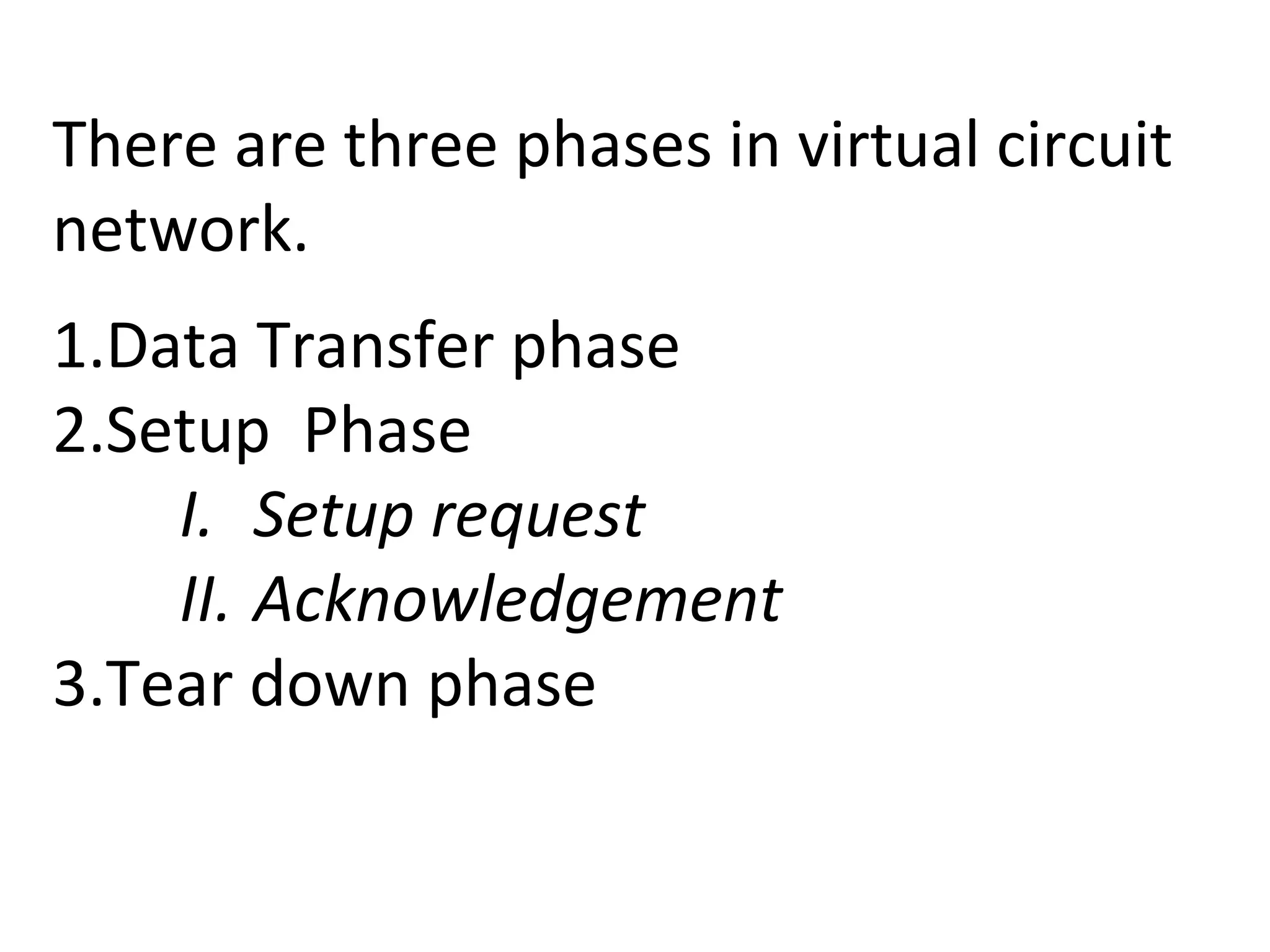
The document covers the concepts of virtual circuit networks and message switching, detailing the three phases involved: data transfer, setup, and teardown. It compares the characteristics and efficiencies of virtual circuit switching, datagram packet switching, and message switching, highlighting their differences in terms of transmission paths, delays, and routing. Additionally, it discusses the historical relevance of message switching, particularly in relation to applications like email.
Introduction to Datacommunication
Topic: Virtual Switching (contd.) & Message
Switching
Lecture #8
Dr Rajiv Srivastava
Director
Sagar Institute of Research & Technology (SIRT)
Sagar Group of Institutions, Bhopal
http://www.sirtbhopal.ac.in
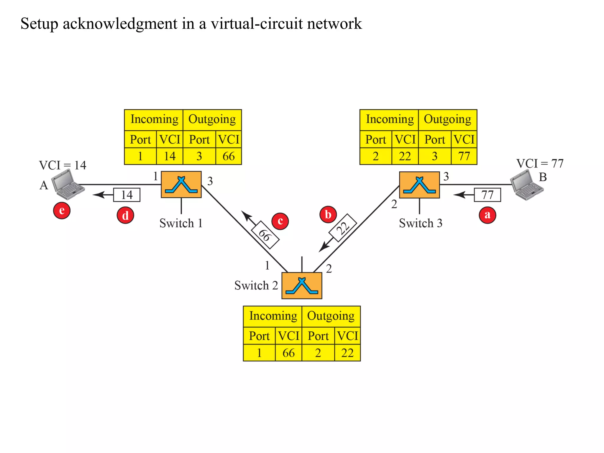
3rd
Phase
Tear Down
• Inthis phase, source after sending all frames
to destination, sends a special frame called
teardown request.
• Destination responds with teardown
confirmation frame
• All the switch delete the corresponding entry
from their tables
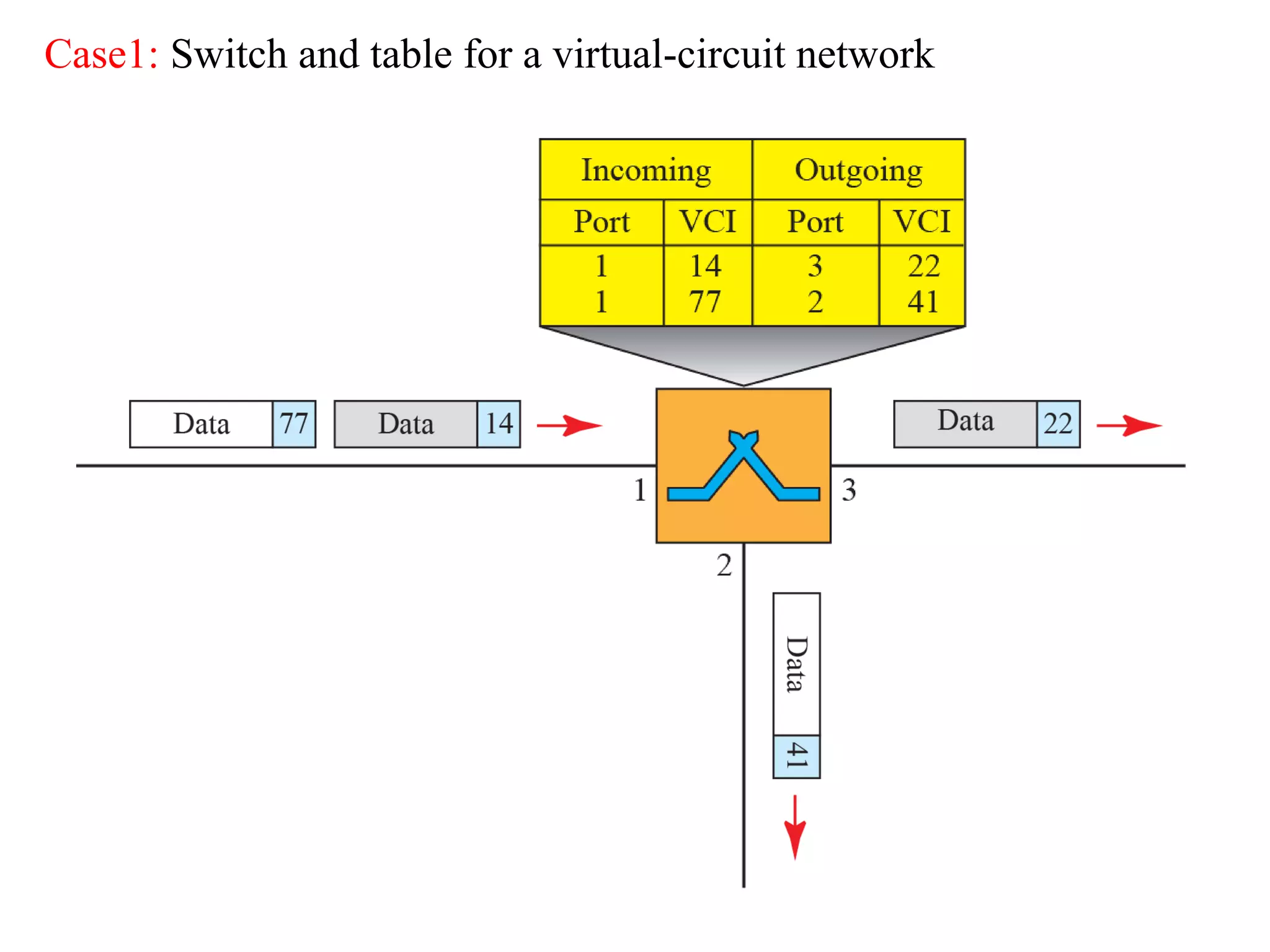
11.
Efficiency
• In virtualcircuit switching, all packets
belonging to the same source & destination
travel the same path, but the packets may
arrive at the destination with different delays
if resource allocation is on demand.
12.
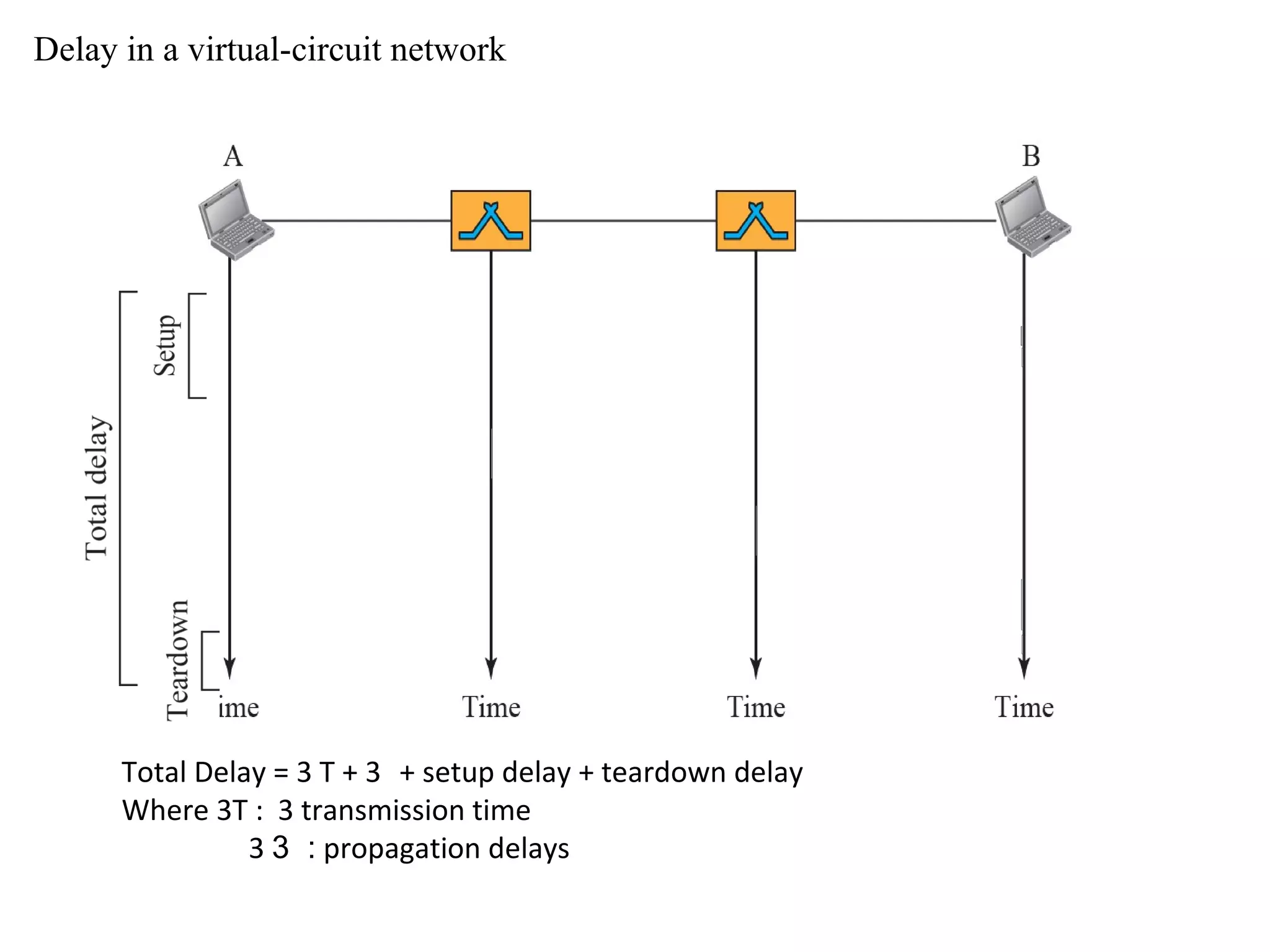
Delay in avirtual-circuit network
Total Delay = 3 T + 3 + setup delay + teardown delay
Where 3T : 3 transmission time
3 :3 propagation delays
13.
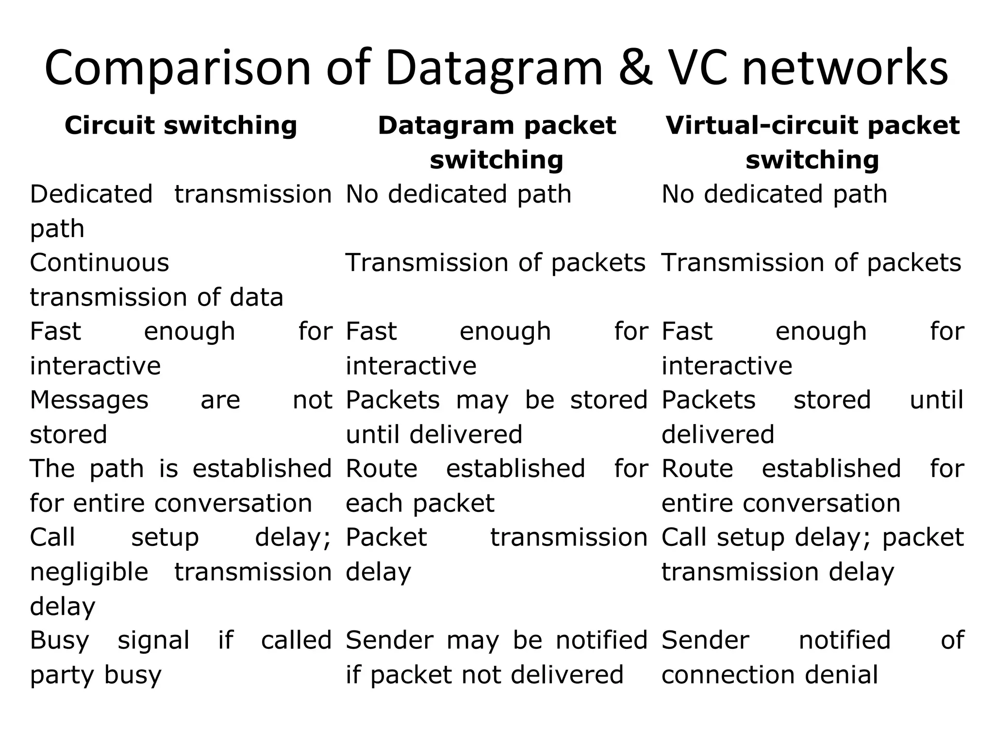
Comparison of Datagram& VC networks
Circuit switching Datagram packet
switching
Virtual-circuit packet
switching
Dedicated transmission
path
No dedicated path No dedicated path
Continuous
transmission of data
Transmission of packets Transmission of packets
Fast enough for
interactive
Fast enough for
interactive
Fast enough for
interactive
Messages are not
stored
Packets may be stored
until delivered
Packets stored until
delivered
The path is established
for entire conversation
Route established for
each packet
Route established for
entire conversation
Call setup delay;
negligible transmission
delay
Packet transmission
delay
Call setup delay; packet
transmission delay
Busy signal if called
party busy
Sender may be notified
if packet not delivered
Sender notified of
connection denial
14.
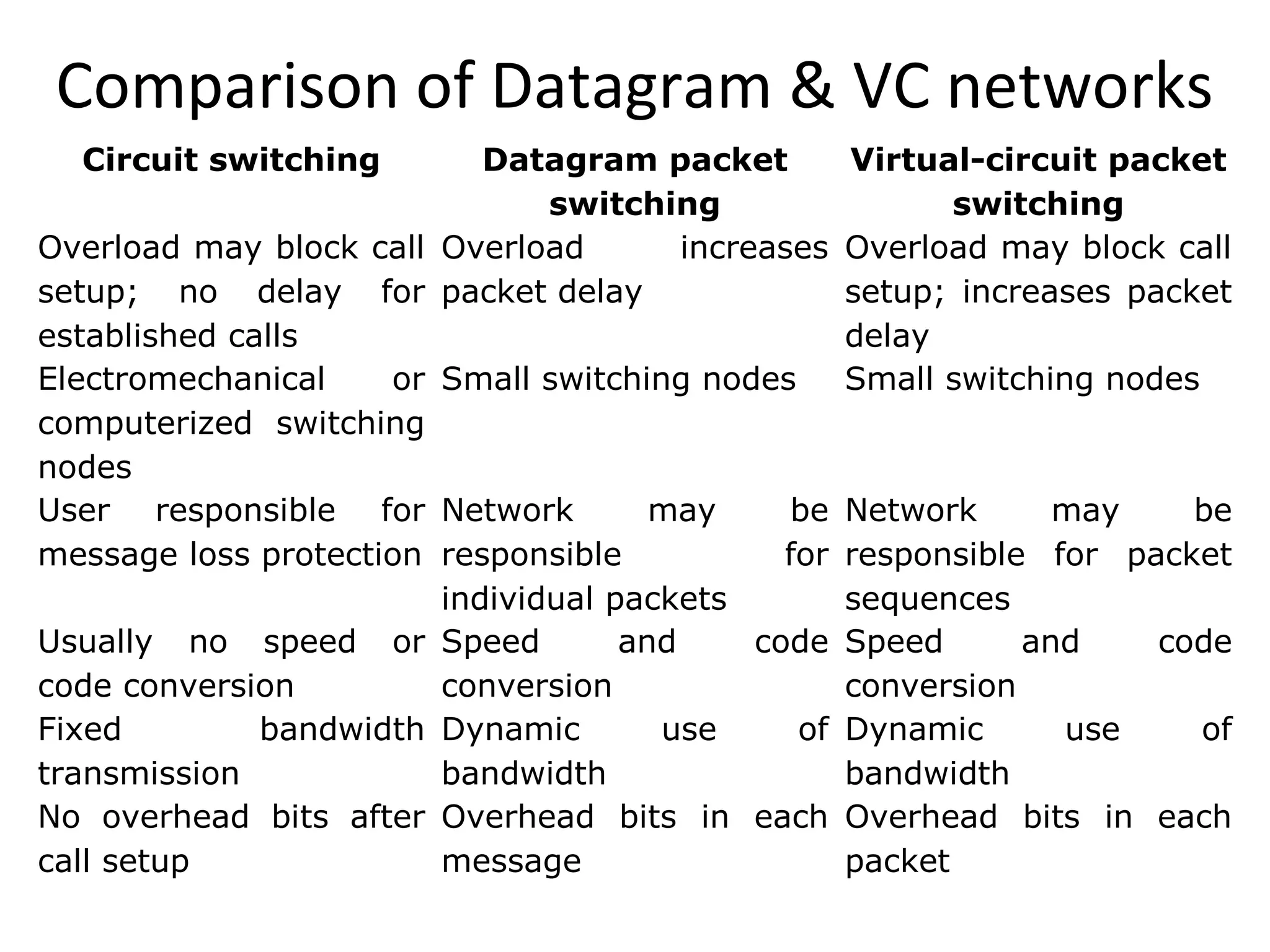
Comparison of Datagram& VC networks
Circuit switching Datagram packet
switching
Virtual-circuit packet
switching
Overload may block call
setup; no delay for
established calls
Overload increases
packet delay
Overload may block call
setup; increases packet
delay
Electromechanical or
computerized switching
nodes
Small switching nodes Small switching nodes
User responsible for
message loss protection
Network may be
responsible for
individual packets
Network may be
responsible for packet
sequences
Usually no speed or
code conversion
Speed and code
conversion
Speed and code
conversion
Fixed bandwidth
transmission
Dynamic use of
bandwidth
Dynamic use of
bandwidth
No overhead bits after
call setup
Overhead bits in each
message
Overhead bits in each
packet
15.
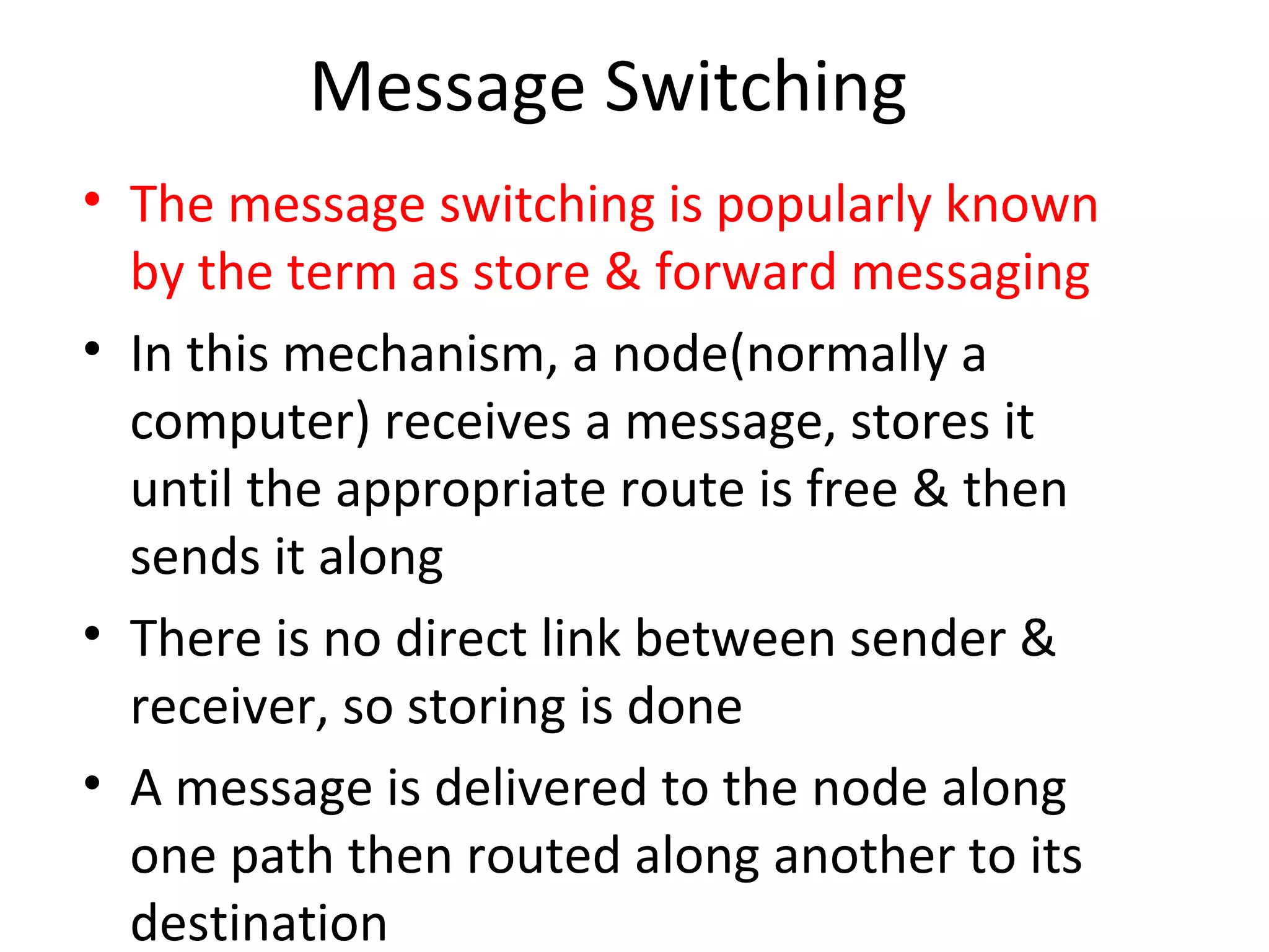
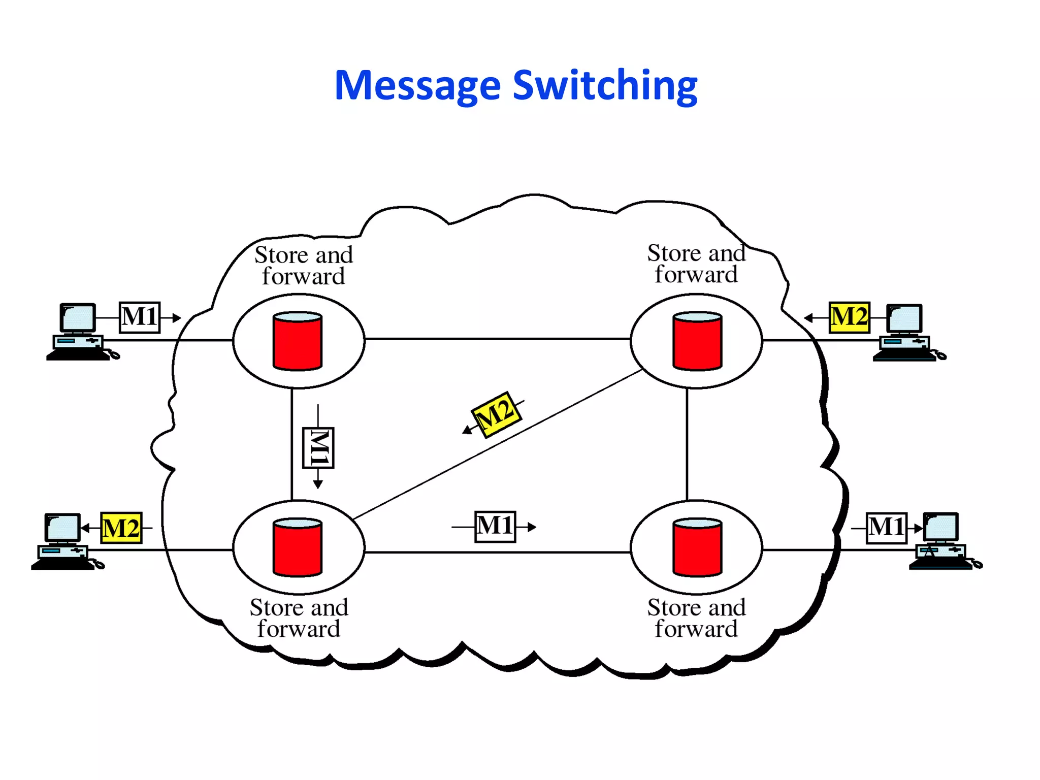
Message Switching
• Themessage switching is popularly known
by the term as store & forward messaging
• In this mechanism, a node(normally a
computer) receives a message, stores it
until the appropriate route is free & then
sends it along
• There is no direct link between sender &
receiver, so storing is done
• A message is delivered to the node along
one path then routed along another to its
destination
16.
• messages arerelayed from secondary storage
in this case whereas in packet switching
messages are forwarded from RAM
• It was a common method in 1960 to 1970
• This method doesn’t work now a days but
implications are still working.
• Just as a application; email can be treated as
good example of message switching
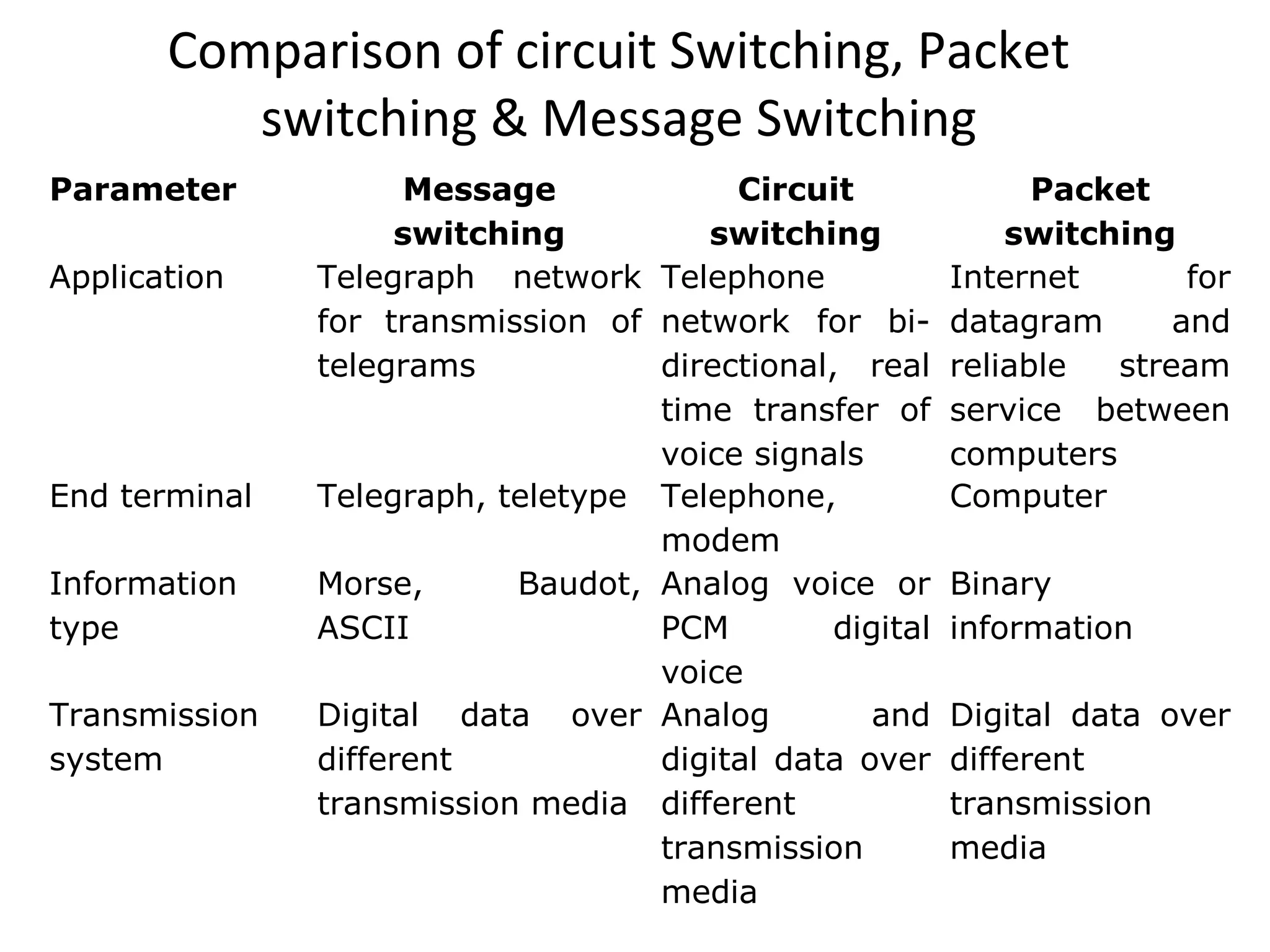
Comparison of circuitSwitching, Packet
switching & Message Switching
Parameter Message
switching
Circuit
switching
Packet
switching
Application Telegraph network
for transmission of
telegrams
Telephone
network for bi-
directional, real
time transfer of
voice signals
Internet for
datagram and
reliable stream
service between
computers
End terminal Telegraph, teletype Telephone,
modem
Computer
Information
type
Morse, Baudot,
ASCII
Analog voice or
PCM digital
voice
Binary
information
Transmission
system
Digital data over
different
transmission media
Analog and
digital data over
different
transmission
media
Digital data over
different
transmission
media
19.
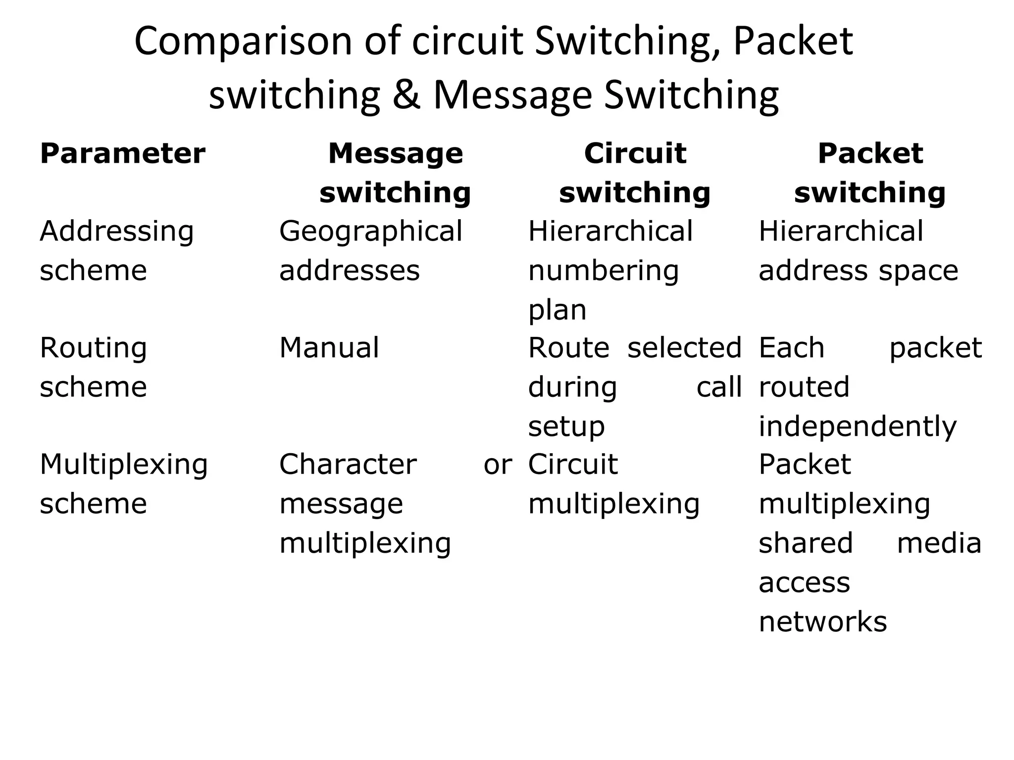
Comparison of circuitSwitching, Packet
switching & Message Switching
Parameter Message
switching
Circuit
switching
Packet
switching
Addressing
scheme
Geographical
addresses
Hierarchical
numbering
plan
Hierarchical
address space
Routing
scheme
Manual Route selected
during call
setup
Each packet
routed
independently
Multiplexing
scheme
Character or
message
multiplexing
Circuit
multiplexing
Packet
multiplexing
shared media
access
networks
20.
Thank You
Dr RajivSrivastava
Director
Sagar Institute of Research & Technology (SIRT)
Sagar Group of Institutions, Bhopal
http://www.sirtbhopal.ac.in