Contents of Feedback Amplifier
1. Introduction to Feedback
2. Feedback Amplifier – Positive & Negative
3. Advantages/Disadvantages of Negative Feedback
4. Basic Feedback Concept
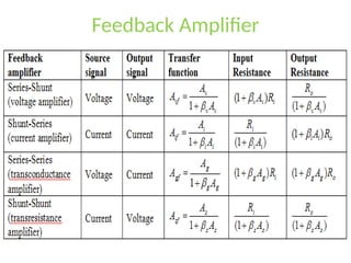
5. Classification of Amplifiers
6. Series – Shunt Configuration
7. Shunt – Series Configuration
8. Series - Series Configuration
9. Shunt – Shunt Configuration
3.
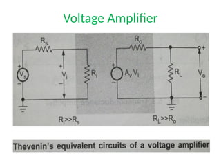
Classification of BasicAmplifiers
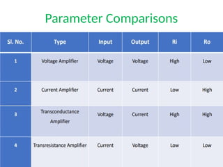
Amplifiers can be classified broadly as,
• Voltage amplifiers.
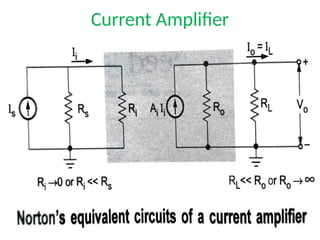
• Current amplifiers.
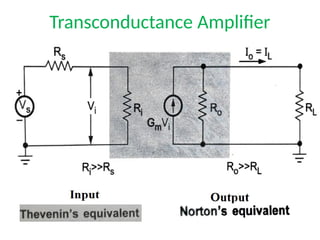
• Transconductance amplifiers.
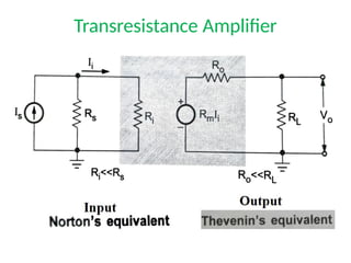
• Transresistance amplifiers.
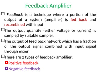
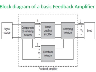
Feedback Amplifier
Feedbackis a technique where a portion of the
output of a system (amplifier) is fed back and
recombined with input
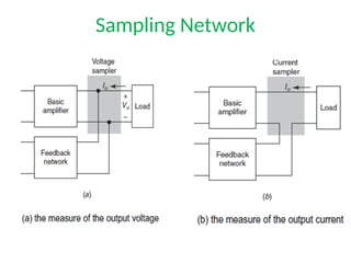
The output quantity (either voltage or current) is
sampled by suitable sampler.
The output of feed back network which has a fraction
of the output signal combined with input signal
through mixer
There are 2 types of feedback amplifier:
Positive feedback
Negative feedback
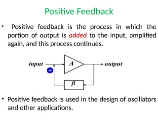
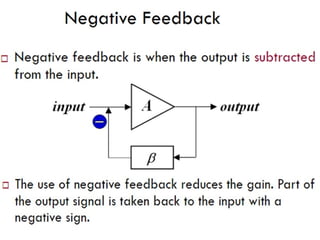
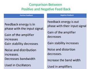
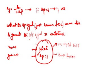
Positive Feedback
• Positivefeedback is the process in which the
portion of output is added to the input, amplified
again, and this process continues.
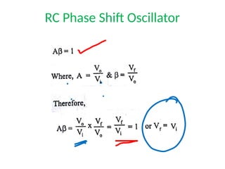
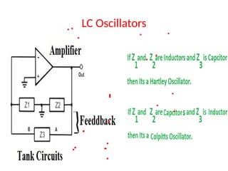
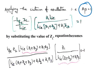
• Positive feedback is used in the design of oscillators
and other applications.
A
b
input output
+
12.
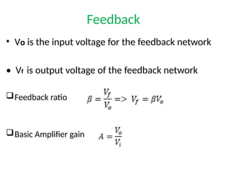
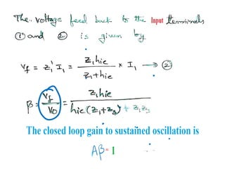
Feedback
• Vo isthe input voltage for the feedback network
• Vf is output voltage of the feedback network
Feedback ratio
Basic Amplifier gain
13.
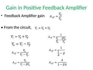
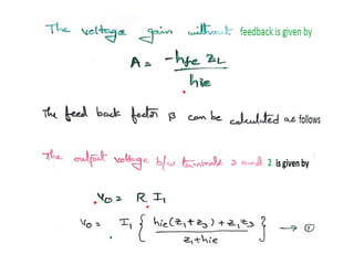
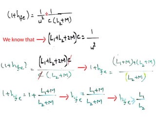
Gain in PositiveFeedback Amplifier
• Feedback Amplifier gain
• From the circuit,
15.
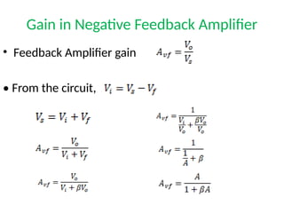
Gain in NegativeFeedback Amplifier
• Feedback Amplifier gain
• From the circuit,
16.
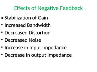
Effects of NegativeFeedback
• Stabilization of Gain
• Increased Bandwidth
• Decreased Distortion
• Decreased Noise
• Increase in Input Impedance
• Decrease in output Impedance
17.
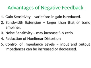
Advantages of NegativeFeedback
1. Gain Sensitivity – variations in gain is reduced.
2. Bandwidth Extension – larger than that of basic
amplifier.
3. Noise Sensitivity – may increase S-N ratio.
4. Reduction of Nonlinear Distortion
5. Control of Impedance Levels – input and output
impedances can be increased or decreased.
18.
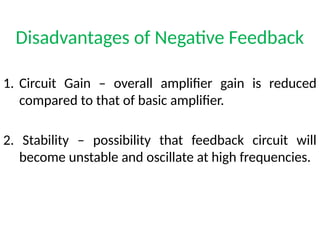
Disadvantages of NegativeFeedback
1. Circuit Gain – overall amplifier gain is reduced
compared to that of basic amplifier.
2. Stability – possibility that feedback circuit will
become unstable and oscillate at high frequencies.
19.
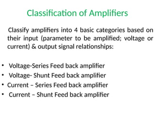
Classification of Amplifiers
Classifyamplifiers into 4 basic categories based on
their input (parameter to be amplified; voltage or
current) & output signal relationships:
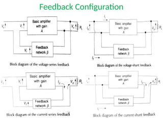
• Voltage-Series Feed back amplifier
• Voltage- Shunt Feed back amplifier
• Current – Series Feed back amplifier
• Current – Shunt Feed back amplifier
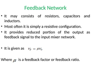
Feedback Network
• Itmay consists of resistors, capacitors and
inductors.
• Most often it is simply a resistive configuration.
• It provides reduced portion of the output as
feedback signal to the input mixer network.
• It is given as
Where is a feedback factor or feedback ratio.
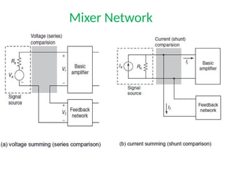
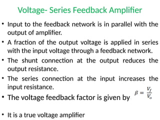
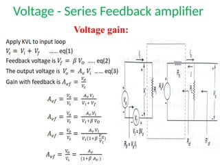
Voltage- Series FeedbackAmplifier
• Input to the feedback network is in parallel with the
output of amplifier.
• A fraction of the output voltage is applied in series
with the input voltage through a feedback network.
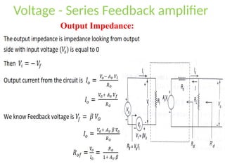
• The shunt connection at the output reduces the
output resistance.
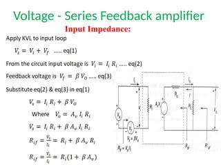
• The series connection at the input increases the
input resistance.
• The voltage feedback factor is given by
• It is a true voltage amplifier
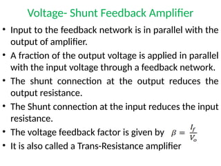
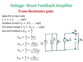
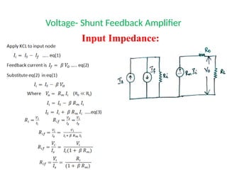
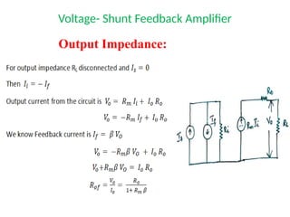
Voltage- Shunt FeedbackAmplifier
• Input to the feedback network is in parallel with the
output of amplifier.
• A fraction of the output voltage is applied in parallel
with the input voltage through a feedback network.
• The shunt connection at the output reduces the
output resistance.
• The Shunt connection at the input reduces the input
resistance.
• The voltage feedback factor is given by
• It is also called a Trans-Resistance amplifier
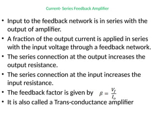
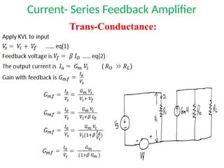
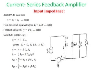
Current- Series FeedbackAmplifier
• Input to the feedback network is in series with the
output of amplifier.
• A fraction of the output current is applied in series
with the input voltage through a feedback network.
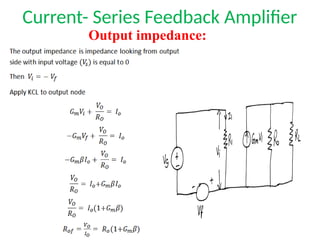
• The series connection at the output increases the
output resistance.
• The series connection at the input increases the
input resistance.
• The feedback factor is given by
• It is also called a Trans-conductance amplifier
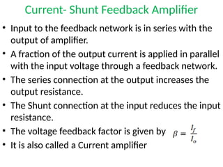
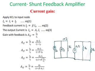
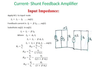
Current- Shunt FeedbackAmplifier
• Input to the feedback network is in series with the
output of amplifier.
• A fraction of the output current is applied in parallel
with the input voltage through a feedback network.
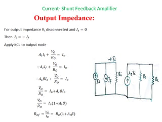
• The series connection at the output increases the
output resistance.
• The Shunt connection at the input reduces the input
resistance.
• The voltage feedback factor is given by
• It is also called a Current amplifier
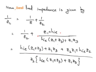
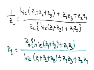
Feedback Amplifier
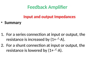
Input andoutput Impedances
• Summary
1. For a series connection at input or output, the
resistance is increased by (1+A).
2. For a shunt connection at input or output, the
resistance is lowered by (1+A).
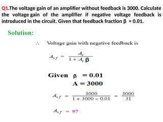
Q1.The voltage gainof an amplifier without feedback is 3000. Calculate
the voltage gain of the amplifier if negative voltage feedback is
introduced in the circuit. Given that feedback fraction β = 0.01.
44.
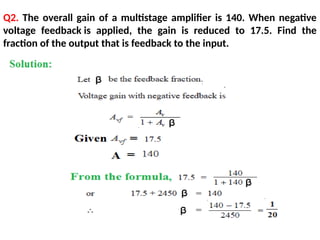
Q2. The overallgain of a multistage amplifier is 140. When negative
voltage feedback is applied, the gain is reduced to 17.5. Find the
fraction of the output that is feedback to the input.
45.
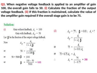
Q3. When negativevoltage feedback is applied to an amplifier of gain
100, the overall gain falls to 50. (i) Calculate the fraction of the output
voltage feedback. (ii) If this fraction is maintained, calculate the value of
the amplifier gain required if the overall stage gain is to be 75.
46.
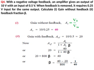
Q4. With anegative voltage feedback, an amplifier gives an output of
10 V with an input of 0.5 V. When feedback is removed, it requires 0.25
V input for the same output. Calculate (i) Gain without feedback (ii)
feedback fraction β.
47.
Q5. The gainand distortion of an amplifier are 150 and 5% respectively
without feedback. If the stage has 10% of its output voltage applied as
negative feedback, find the distortion of the amplifier with feedback.
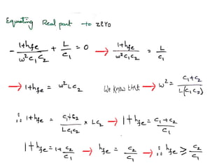
It may be seen that by the application of negative voltage feedback, the
amplifier distortion is reduced from 5% to 0.313%.
48.
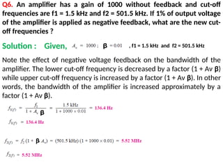
Q6. An amplifierhas a gain of 1000 without feedback and cut-off
frequencies are f1 = 1.5 kHz and f2 = 501.5 kHz. If 1% of output voltage
of the amplifier is applied as negative feedback, what are the new cut-
off frequencies ?
Note the effect of negative voltage feedback on the bandwidth of the
amplifier. The lower cut-off frequency is decreased by a factor (1 + Aν β)
while upper cut-off frequency is increased by a factor (1 + Aν β). In other
words, the bandwidth of the amplifier is increased approximately by a
factor (1 + Aν β).
Solution : Given, , f1 = 1.5 kHz and f2 = 501.5 kHz
Crystal Oscillator
• Usedwhen accuracy and stability of fo is utmost
important.
• Where do you need such high stability of frequency
of oscillations ?
• Instead of an inductor, it uses a crystal of quartz,
tourmaline, or Rochelle salt.
• Piezoelectric effect.
• The crystal is suitably cut and then mounted
between two metallic plates.
94.
• Crystal oscillatoris most commonly used oscillator with
high-frequency stability. They are usually, fixed frequency
oscillators where stability and accuracy are the primary
considerations.
• In order to design a stable and accurate LC oscillator for
the upper HF and higher frequencies it is absolutely
necessary to have a crystal control; hence, the reason for
crystal oscillators.
• In crystal the primary frequency determining element is a
quartz crystal. Because of the inherent characteristics of the
quartz crystal the crystal oscillator may be held to extreme
accuracy of frequency stability.
Crystal Oscillator
95.
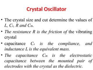
Crystal Oscillator
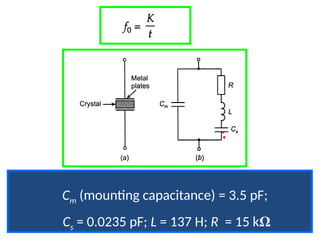
• Thecrystal size and cut determine the values of
L, Cs, R and Cm.
• The resistance R is the friction of the vibrating
crystal
• capacitance Cs is the compliance, and
inductance L is the equivalent mass.
• The capacitance Cm is the electrostatic
capacitance between the mounted pair of
electrodes with the crystal as the dielectric.
96.
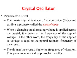
Crystal Oscillator
• PiezoelectricEffect
– The quartz crystal is made of silicon oxide (SiO2) and
exhibits a property called the piezoelectric
– When a changing an alternating voltage is applied across
the crystal, it vibrates at the frequency of the applied
voltage. In the other word, the frequency of the applied
ac voltage is equal to the natural resonant frequency of
the crystal.
– The thinner the crystal, higher its frequency of vibration.
This phenomenon is called piezoelectric effect.
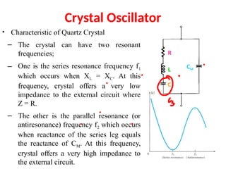
Crystal Oscillator
• Characteristicof Quartz Crystal
– The crystal can have two resonant
frequencies;
– One is the series resonance frequency f1
which occurs when XL = XC. At this
frequency, crystal offers a very low
impedance to the external circuit where
Z = R.
– The other is the parallel resonance (or
antiresonance) frequency f2 which occurs
when reactance of the series leg equals
the reactance of CM. At this frequency,
crystal offers a very high impedance to
the external circuit.
R
L
C
CM
99.
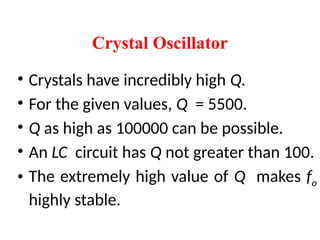
• Crystals haveincredibly high Q.
• For the given values, Q = 5500.
• Q as high as 100000 can be possible.
• An LC circuit has Q not greater than 100.
• The extremely high value of Q makes fo
highly stable.
Crystal Oscillator
100.
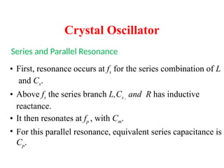
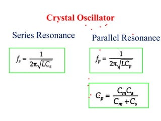
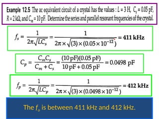
Series and ParallelResonance
• First, resonance occurs at fs for the series combination of L
and Cs.
• Above fs the series branch L,Cs , and R has inductive
reactance.
• It then resonates at fp , with Cm.
• For this parallel resonance, equivalent series capacitance is
Cp.
Crystal Oscillator
• Normally, Csis much smaller than Cm.
• Therefore, Cp is slightly less than Cs.
• Hence, the frequency fp is slightly greater than fs.
• The crystal is inductive only between the
frequencies fs and fp.
• The frequency of oscillation must lie between
these frequencies.
• Hence the stability.
Crystal Oscillator