Downloaded 299 times


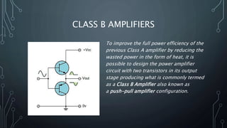
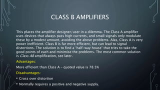
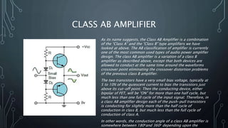


The document presents an overview of different classes of amplifiers, including Class A, Class B, Class AB, and Class C. Class A amplifiers provide good signal quality but have low efficiency, while Class B amplifiers improve efficiency at the expense of potential distortion. Class AB amplifiers offer a compromise between efficiency and linearity, and Class C amplifiers, though highly efficient, are typically unsuitable for audio applications due to significant distortion.


