2. Worm Gears: Introduction
• Worm gear drives are used to transmit power between two non-
intersecting shafts, which are, in general, at right angles to each other.
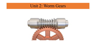
• The worm gear drive consists of a worm and a worm wheel.
• The worm is a threaded screw, while the worm wheel is a toothed
gear.
• The teeth on the worm wheel envelope the threads on the worm and
give line contact between mating parts.
3. Advantages
• High reduction ratio
• Compact
• Smooth and silent operation
• Provision can be made for self locking
Disadvantages
• Low Efficiency
• Higher material cost
• High heat generation
• Power transmitting capacity is low
Worm Gears: Introduction
4. • It is necessary to consider the relationship between the number of starts on the
worm and the efficiency to decide the suitability of worm gear drive for a
particular application.
Two guidelines are as follows:
• (i) Single-threaded worm gives large speed reduction, however, the efficiency is
low. The large velocity ratio is obtained at the cost of efficiency.
• (ii) Multi-threaded worm gives high efficiency, however, the speed reduction is
low. The high efficiency is obtained at the cost of speed reduction.
Worm Gears: Introduction
5. • A pair of worm gears is specified and designated by :
z1/z2/q/m
Where, z1 = number of starts on the worm
z2 = Number of teeth on the worm wheel
q = Diametral quotient
m = module (mm)
The diametral quotient is given by,
q= d1/m
where d1 is the pitch circle diameter of the worm
Worm Gears: Terminologies
7. • Axial Pitch (px) of the worm is defined as the distance measured from a
point on one thread to the corresponding point on the adjacent thread,
measured along the axis of the worm
• Lead (l) of the worm is defined as the distance that a point on the helical
profile will move when the worm is rotated through one revolution.
• It is the thread advance in one turn. For single-start threads, the lead is
equal to the axial pitch. For double-start threads, the lead is twice the
axial pitch, and so on. l = px z1
Worm Gears: Terminologies
9. • When one thread of the worm is developed, it
becomes the hypotenuse of a triangle as
shown in Fig.
• The base of this triangle is equal to the lead of
the worm, while the altitude is equal to the
circumference of the worm.
Worm Gears: Terminologies
10. Pressure Angle The tooth pressure angle (a) is
measured in a plane containing the axis of the
worm and it is equal to one-half of the thread
angle.
13. • Preferred values of q 8, 10, 12.5, 16, 20 and 25.
• The number of starts (z1) on the worm is usually taken as 1, 2 or 4.
Worm Gears: Terminologies
19. • The coefficient of friction in worm gear
drives depends upon the rubbing speed.
• The rubbing speed is the relative
velocity between the worm and the
wheel.
FRICTION WORM GEARS
20. • The variation of the coefficient of friction with
respect to rubbing velocity is shown in Fig.
• The values of the coefficient of friction in this
figure are based on the following two
assumptions:
• The worm wheel is made of phosphorbronze,
while the worm is made of casehardened steel.
FRICTION WORM GEARS
21.
22. • Since the teeth of worm wheel are weaker than the threads of worm, the design for
strength can be based on Lewis’ equation as applied to worm wheel teeth.
• The maximum permissible torque that the worm wheel can withstand without
bending failure is given by the lower of the following two values2 :
STRENGTH RATING OF WORM GEARS
28. • The efficiency of a worm gear drive is low
and the work done by friction is converted
into heat.
• When the worm gears operate continuously,
considerable amount of heat is generated.
• The rate of heat generated (Hg ) is given by,
Hg = 1000* (1 – η)*kW (a)
• The heat is dissipated through the
lubricating oil to the housing wall and
finally to the surrounding air.
• The rate of heat dissipated (Hd) by the
housing walls to the surrounding air is given
by,
Hd = k (t – to)A (b)
Thermal Considerations in Worm Gears
30. A pair of worm and worm wheel is designated as 3/60/10/6 , The worm is transmitting 5 kW power
at 1440 rpm to the worm wheel. The coeffi cient of friction is 0.1 and the normal pressure angle is
20°. Determine the components of the gear tooth force acting on the worm and the worm wheel.
Given data: Z1=3, Z2= 60 q= 10 m=6 Kw=5 n= 1440
31.
32. 1 kW power at 720 rpm is supplied to the worm shaft. The number of starts for threads of the worm is four with a 50
mm pitch–circle diameter. The worm wheel has 30 teeth with 5 mm module. The normal pressure angle is 20°.
Calculate the efficiency of the worm gear drive and the power lost in friction.
Given data: KW= 1 n1= 720, d1= 50mm, z1=4, z2= 30, m=5
33.
34. A pair of worm and worm wheel is designated as, 1/30/10/10 The input speed of the worm is 1200 rpm. The
worm wheel is made of centrifugally cast, phosphorbronze and the worm is made of case-hardened carbon
steel 14C6. Determine the power transmitting capacity based on the beam strength and wear Strength
Assume following: Xb1=0.25, Xb2= 0.48 Sb1= 28.2, Sb2= 7.0
Sc1= 4.93, Sc2= 1.55 Xc1= 0.112, Xc2= 0.26
Yz=1.143
Given data: Z1= 1, Z2= 30, q=10, m=10, n1= 1200 rpm,
lr= (da1+2c) Sin-1 [F/(da1+2c)]
c= 0.2 m cosγ
35.
36.
37. A worm gear box with an effective surface area of 1.5 m2 is operating in still air with a heat transfer coefficient of 15
W/m2°C. The temperature rise of the lubricating oil above the atmospheric temperature is limited to 50°C. The worm gears
are designated as, 1/30/10/8 . The worm shaft is rotating at 1440 rpm and the normal pressure angle is 20°. Calculate the
power transmitting capacity based on the thermal considerations.