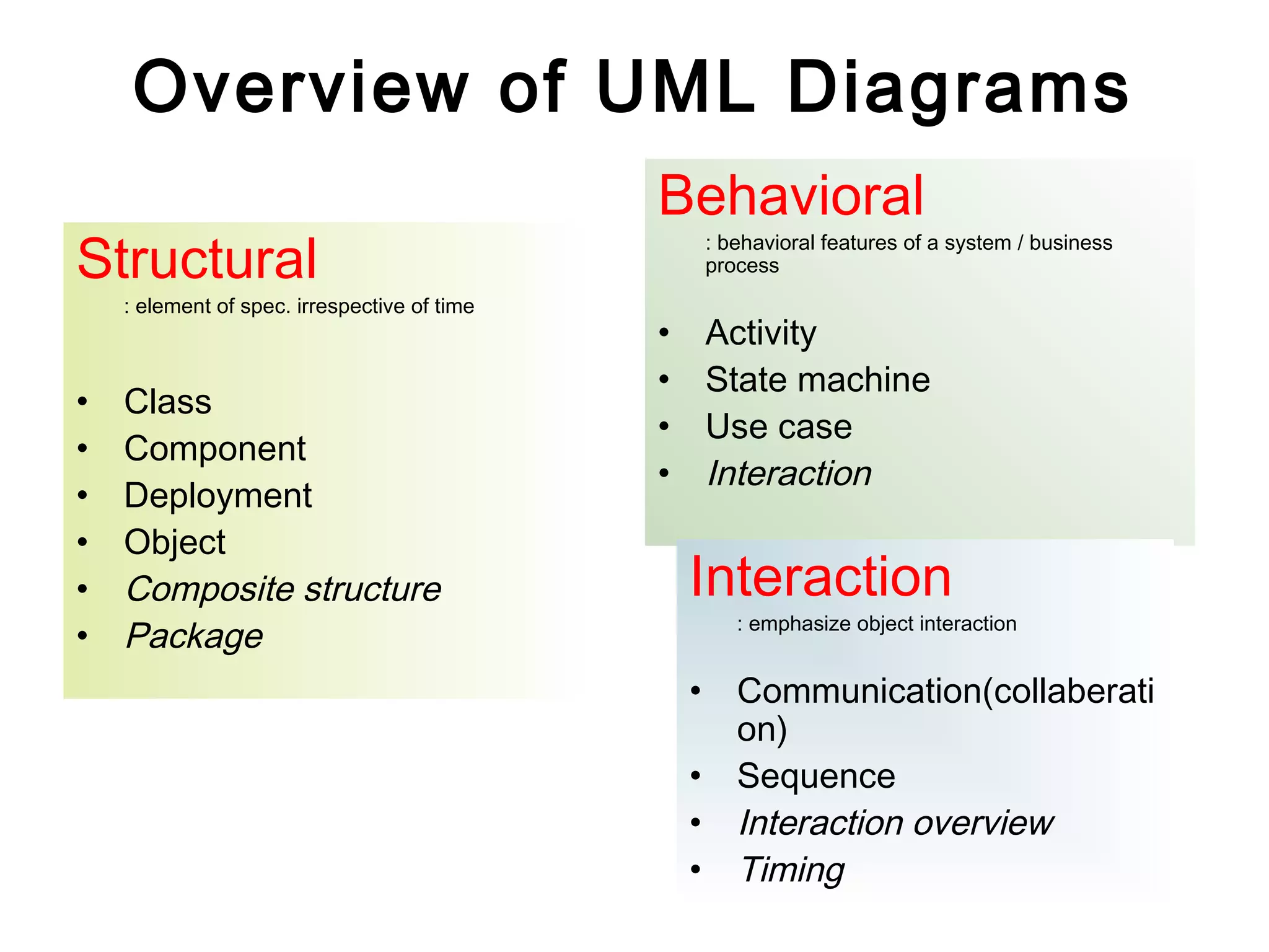
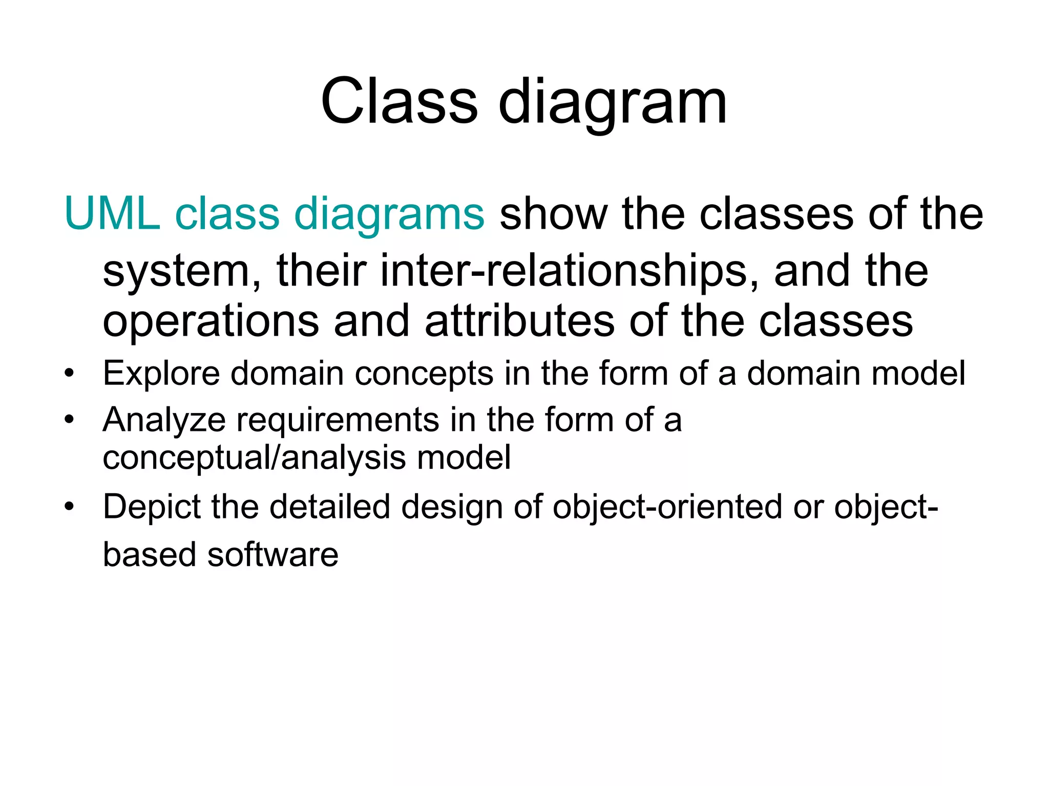
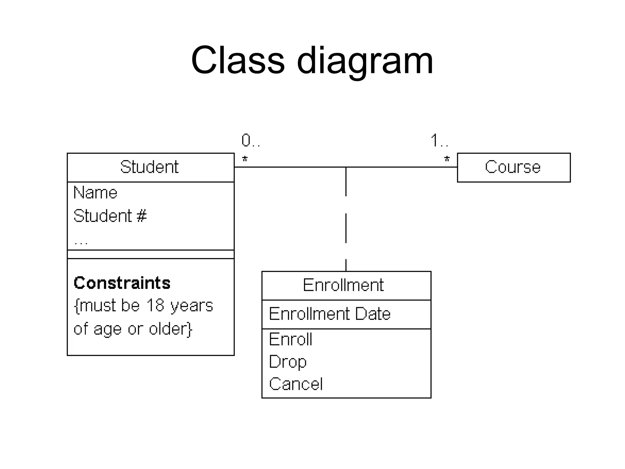
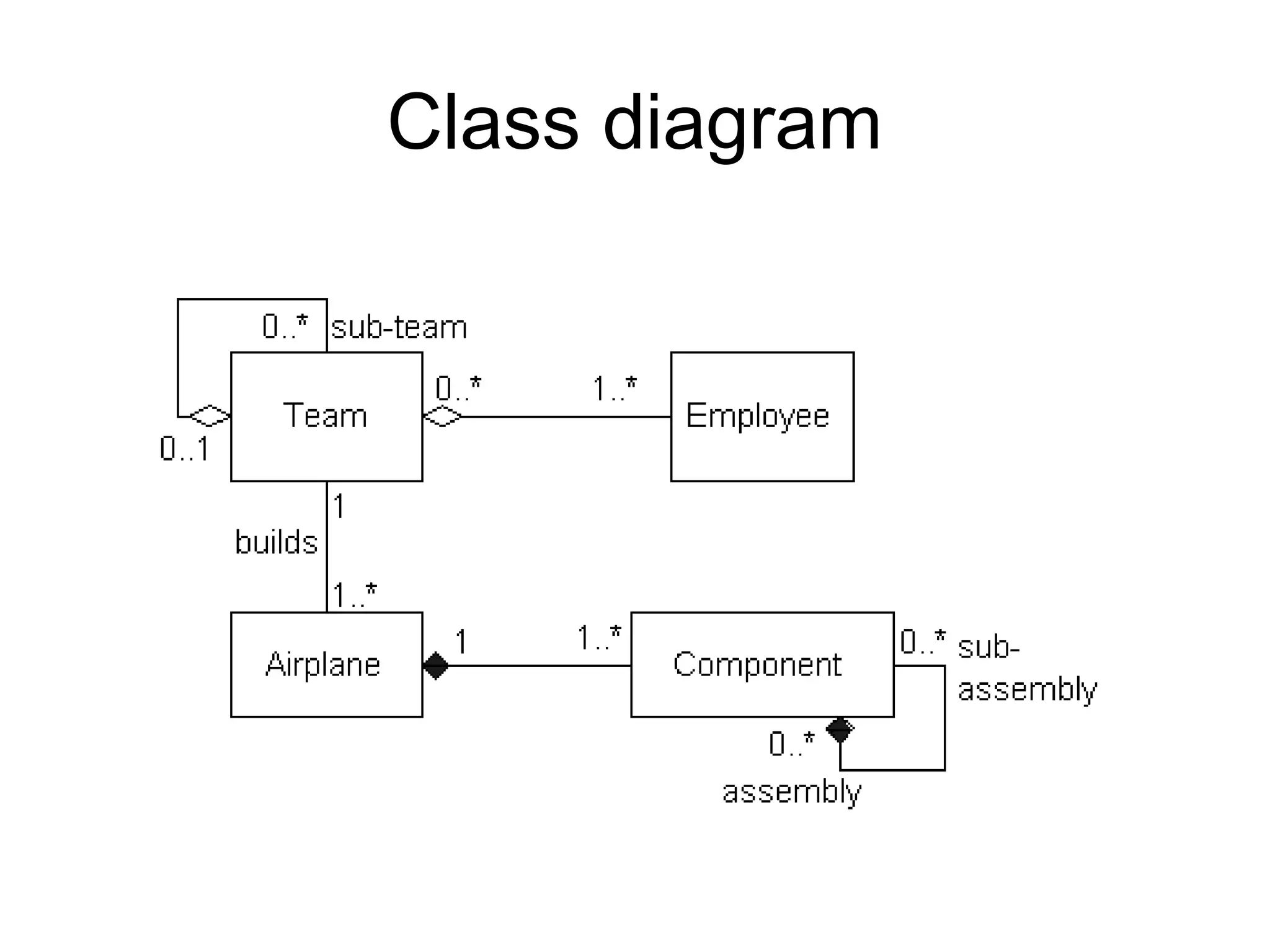
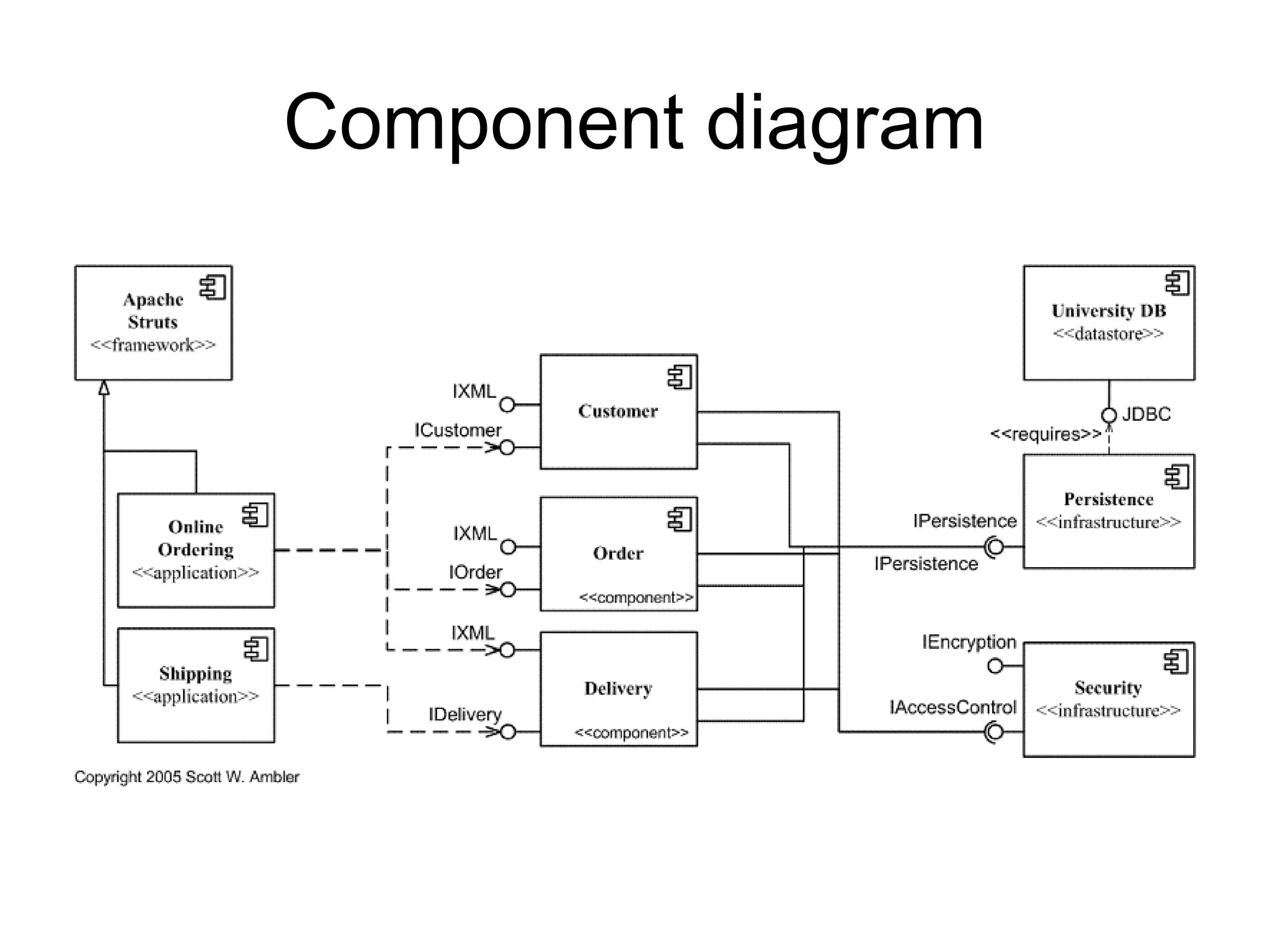
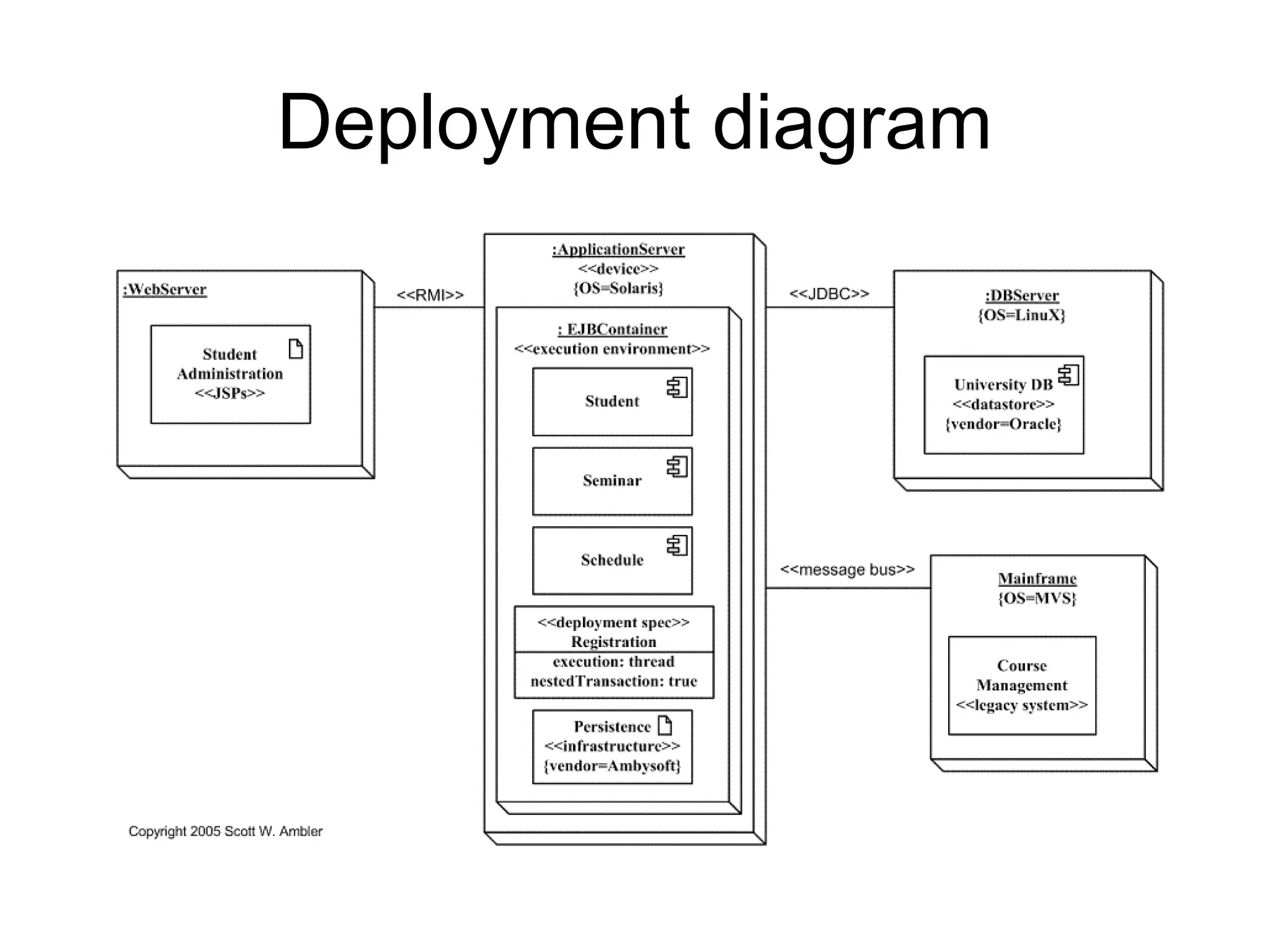
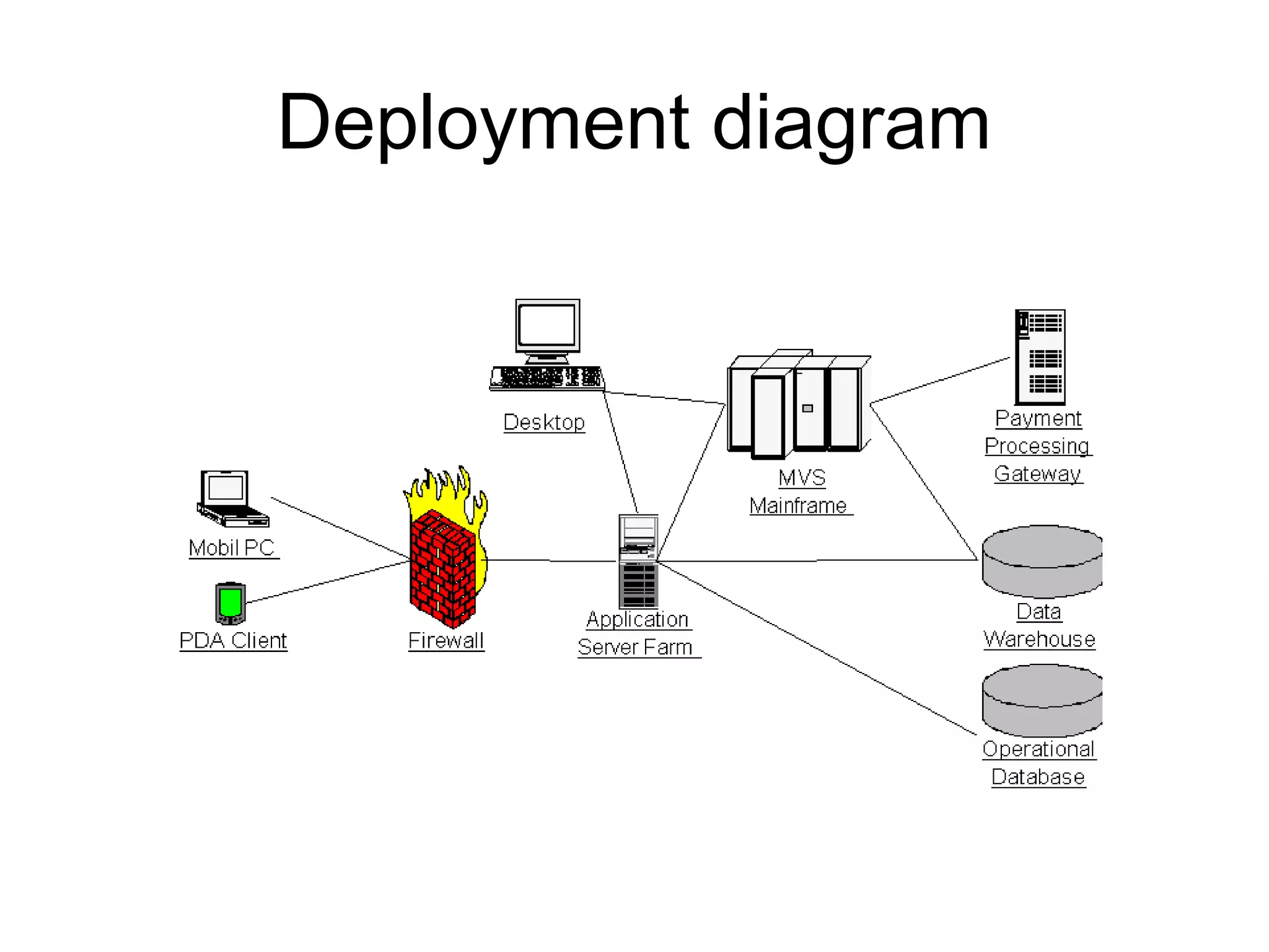
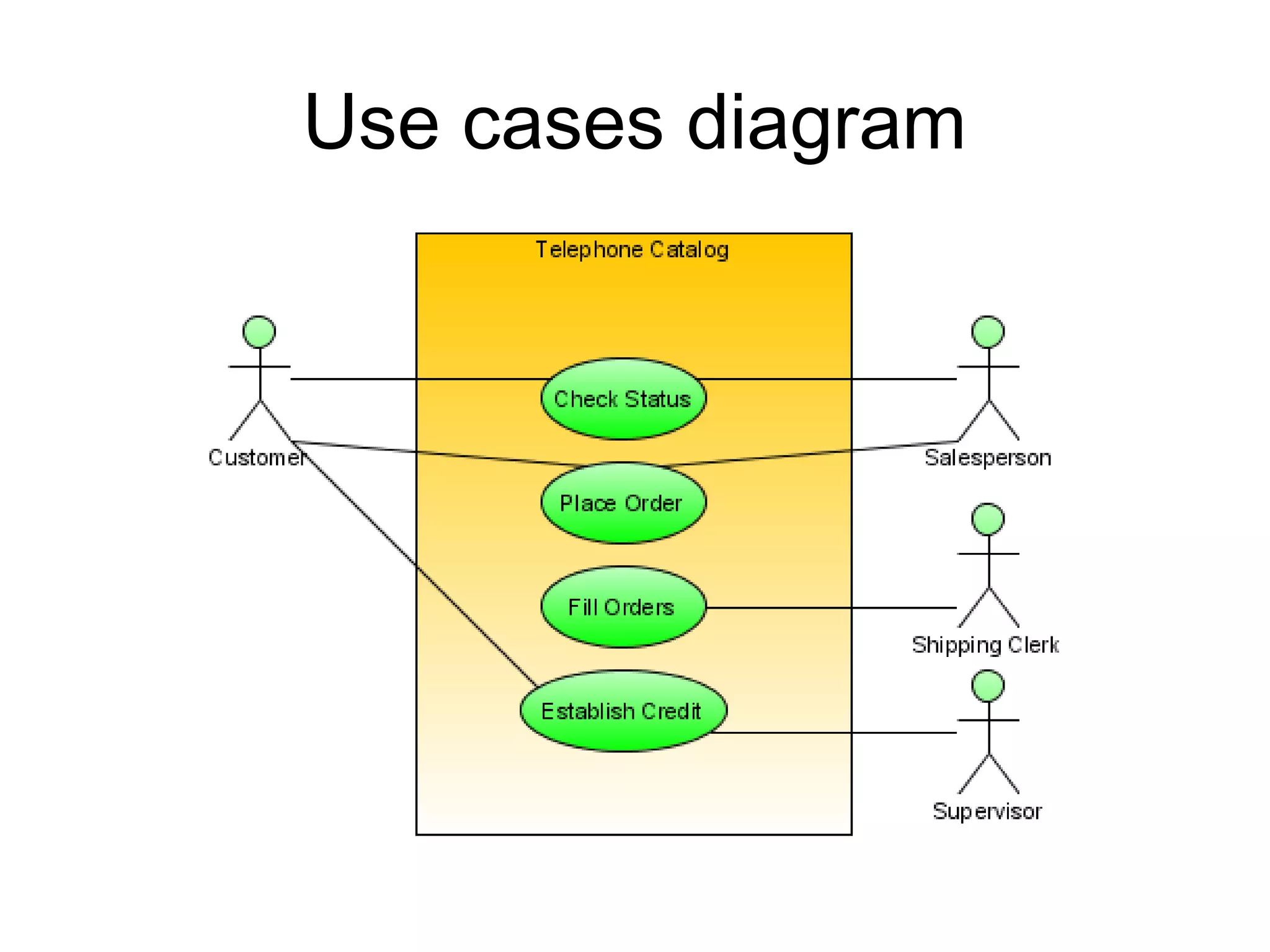
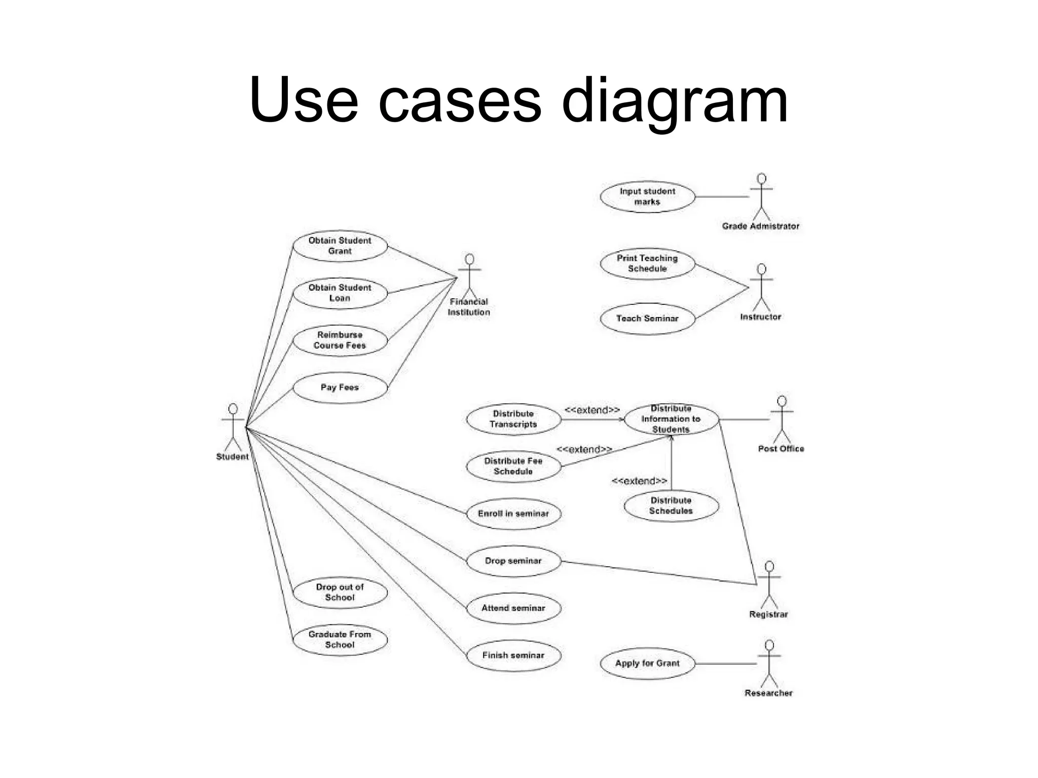
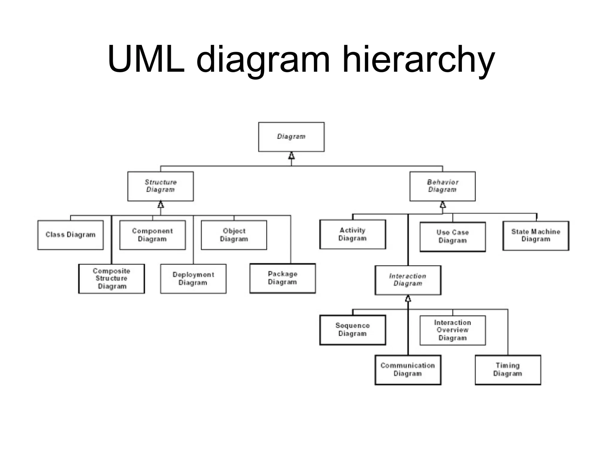
UML Diagrams
Thanks to Jung Woo
What is UML?
• Standard  language for specifying, visualizing,
constructing, and documenting the artifacts of software
systems, business modeling and other non-software
systems.
• The UML represents a collection of best engineering
practices that have proven successful in the modeling of
large and complex systems.
• The UML is a very important part of developing object
oriented software and the software development
process. 
• The UML uses mostly graphical notations to express the
design of software projects. 
• Using the UML helps project teams communicate,
explore potential designs, and validate the architectural
design of the software.
Overview of UML Diagrams
Structural
: element of spec. irrespective of time
• Class
• Component
• Deployment
• Object
• Composite structure
• Package
Behavioral
: behavioral features of a system / business
process
• Activity
• State machine
• Use case
• Interaction
Interaction
: emphasize object interaction
• Communication(collaberati
on)
• Sequence
• Interaction overview
• Timing
Class diagram
UML class diagrams show the classes of the
system, their inter-relationships, and the
operations and attributes of the classes
• Explore domain concepts in the form of a domain model
• Analyze requirements in the form of a
conceptual/analysis model
• Depict the detailed design of object-oriented or object-
based software
Class diagram
Class diagram
Component diagram
UML component diagrams shows the
dependencies among software
components, including the classifiers that
specify them (for example implementation
classes) and the artifacts that implement
them; such as source code files, binary
code files, executable files, scripts and
tables.
Component diagram
Deployment diagram
UML deployment diagram depicts a static
view of the run-time configuration of
hardware nodes and the software
components that run on those nodes.
Deployment diagrams show the hardware
for your system, the software that is
installed on that hardware, and the
middleware used to connect the disparate
machines to one another.
Deployment diagram
Deployment diagram
Object diagram
• UML 2 Object diagrams (instance
diagrams), are useful for exploring real
world examples of objects and the
relationships between them. It shows
instances instead of classes. They are
useful for explaining small pieces with
complicated relationships, especially
recursive relationships.
Object diagram
Package diagram
• UML 2 Package diagrams simplify
complex class diagrams, it can group
classes into packages. A package is a
collection of logically related UML
elements. Packages are depicted as file
folders and can be used on any of the
UML diagrams.
Package diagram
Composite structure diagram
• UML 2 Composite structure diagrams
used to explore run-time instances of
interconnected instances collaborating
over communications links. It shows the
internal structure (including parts and
connectors) of a structured classifier or
collaboration.
Composite structure diagram
Activity diagram
• UML 2 Activity diagrams helps to describe
the flow of control of the target system,
such as the exploring complex business
rules and operations, describing the use
case also the business process. It is
object-oriented equivalent of flow charts
and data-flow diagrams (DFDs).
Activity diagram
Activity diagram
State machine diagram
• UML 2 State machine diagrams can show
the different states of an entity also how
an entity responds to various events by
changing from one state to another. The
history of an entity can best be modeled
by a finite state diagram.
State machine diagram
Use cases diagram
UML 2 Use cases diagrams describes the behavior of the
target system from an external point of view. Use cases
describe "the meat" of the actual requirements.
• Use cases. A use case describes a sequence of
actions that provide something of measurable value to
an actor and is drawn as a horizontal ellipse.
• Actors. An actor is a person, organization, or external
system that plays a role in one or more interactions with
your system. Actors are drawn as stick figures.
• Associations.  Associations between actors and use
cases are indicated by solid lines. An association exists
whenever an actor is involved with an interaction
described by a use case.
Use cases diagram
Use cases diagram
Use cases diagram
Communication diagram
• UML 2 Communication diagrams used to
model the dynamic behavior of the use
case. When compare to Sequence
Diagram, the Communication Diagram is
more focused on showing the
collaboration of objects rather than the
time sequence.
Communication diagram
Sequence diagram
• UML 2 Sequence diagrams models the
collaboration of objects based on a time
sequence. It shows how the objects
interact with others in a particular scenario
of a use case.
Sequence diagram
Timing diagram
• UML 2 Timing diagrams shows the
behavior of the objects in a given period of
time. Timing diagram is a special form of a
sequence diagram. The differences
between timing diagram and sequence
diagram are the axes are reversed so that
the time are increase from left to right and
the lifelines are shown in separate
compartments arranged vertically.
Timing diagram
Timing diagram
Interaction overview diagram
• UML 2 Interaction overview diagrams
focuses on the overview of the flow of
control of the interactions. It is a variant of
the Activity Diagram where the nodes are
the interactions or interaction occurrences.
It describes the interactions where
messages and lifelines are hidden.
Interaction overview diagram
UML diagram hierarchy
References
• http://www.agilemodeling.com/
• http://www.visual-
paradigm.com/VPGallery/diagrams/index.html
• http://bdn.borland.com/article/0,1410,31863,00.h
tml
• http://en.wikipedia.org/wiki/Unified_Modeling_La
nguage
• http://pigseye.kennesaw.edu/~dbraun/csis4650/
A&D/UML_tutorial/index.htm

Uml Diagrams

  • 1.
  • 2.
    What is UML? •Standard  language for specifying, visualizing, constructing, and documenting the artifacts of software systems, business modeling and other non-software systems. • The UML represents a collection of best engineering practices that have proven successful in the modeling of large and complex systems. • The UML is a very important part of developing object oriented software and the software development process.  • The UML uses mostly graphical notations to express the design of software projects.  • Using the UML helps project teams communicate, explore potential designs, and validate the architectural design of the software.
  • 3.
    Overview of UMLDiagrams Structural : element of spec. irrespective of time • Class • Component • Deployment • Object • Composite structure • Package Behavioral : behavioral features of a system / business process • Activity • State machine • Use case • Interaction Interaction : emphasize object interaction • Communication(collaberati on) • Sequence • Interaction overview • Timing
  • 4.
    Class diagram UML classdiagrams show the classes of the system, their inter-relationships, and the operations and attributes of the classes • Explore domain concepts in the form of a domain model • Analyze requirements in the form of a conceptual/analysis model • Depict the detailed design of object-oriented or object- based software
  • 5.
  • 6.
  • 7.
    Component diagram UML componentdiagrams shows the dependencies among software components, including the classifiers that specify them (for example implementation classes) and the artifacts that implement them; such as source code files, binary code files, executable files, scripts and tables.
  • 8.
  • 9.
    Deployment diagram UML deploymentdiagram depicts a static view of the run-time configuration of hardware nodes and the software components that run on those nodes. Deployment diagrams show the hardware for your system, the software that is installed on that hardware, and the middleware used to connect the disparate machines to one another.
  • 10.
  • 11.
  • 12.
    Object diagram • UML2 Object diagrams (instance diagrams), are useful for exploring real world examples of objects and the relationships between them. It shows instances instead of classes. They are useful for explaining small pieces with complicated relationships, especially recursive relationships.
  • 13.
  • 14.
    Package diagram • UML2 Package diagrams simplify complex class diagrams, it can group classes into packages. A package is a collection of logically related UML elements. Packages are depicted as file folders and can be used on any of the UML diagrams.
  • 15.
  • 16.
    Composite structure diagram •UML 2 Composite structure diagrams used to explore run-time instances of interconnected instances collaborating over communications links. It shows the internal structure (including parts and connectors) of a structured classifier or collaboration.
  • 17.
  • 18.
    Activity diagram • UML2 Activity diagrams helps to describe the flow of control of the target system, such as the exploring complex business rules and operations, describing the use case also the business process. It is object-oriented equivalent of flow charts and data-flow diagrams (DFDs).
  • 19.
  • 20.
  • 21.
    State machine diagram •UML 2 State machine diagrams can show the different states of an entity also how an entity responds to various events by changing from one state to another. The history of an entity can best be modeled by a finite state diagram.
  • 22.
  • 23.
  • 24.
    Use cases diagram UML2 Use cases diagrams describes the behavior of the target system from an external point of view. Use cases describe "the meat" of the actual requirements. • Use cases. A use case describes a sequence of actions that provide something of measurable value to an actor and is drawn as a horizontal ellipse. • Actors. An actor is a person, organization, or external system that plays a role in one or more interactions with your system. Actors are drawn as stick figures. • Associations.  Associations between actors and use cases are indicated by solid lines. An association exists whenever an actor is involved with an interaction described by a use case.
  • 25.
  • 26.
  • 27.
  • 28.
    Communication diagram • UML2 Communication diagrams used to model the dynamic behavior of the use case. When compare to Sequence Diagram, the Communication Diagram is more focused on showing the collaboration of objects rather than the time sequence.
  • 29.
  • 30.
    Sequence diagram • UML2 Sequence diagrams models the collaboration of objects based on a time sequence. It shows how the objects interact with others in a particular scenario of a use case.
  • 31.
  • 32.
    Timing diagram • UML2 Timing diagrams shows the behavior of the objects in a given period of time. Timing diagram is a special form of a sequence diagram. The differences between timing diagram and sequence diagram are the axes are reversed so that the time are increase from left to right and the lifelines are shown in separate compartments arranged vertically.
  • 33.
  • 34.
  • 35.
    Interaction overview diagram •UML 2 Interaction overview diagrams focuses on the overview of the flow of control of the interactions. It is a variant of the Activity Diagram where the nodes are the interactions or interaction occurrences. It describes the interactions where messages and lifelines are hidden.
  • 36.
  • 37.
  • 38.
  • 39.
    References • http://www.agilemodeling.com/ • http://www.visual- paradigm.com/VPGallery/diagrams/index.html •http://bdn.borland.com/article/0,1410,31863,00.h tml • http://en.wikipedia.org/wiki/Unified_Modeling_La nguage • http://pigseye.kennesaw.edu/~dbraun/csis4650/ A&D/UML_tutorial/index.htm

Editor's Notes

  • #18 Dashed oval : collaboration , rectangular : instances of any type of classifier, including classes, objects, or interfaces
  • #20 Dashed oval : collaboration , rectangular : instances of any type of classifier, including classes, objects, or interfaces
  • #21 A swimlane is a way to group activities performed by the same actor on an activity diagram or to group activities in a single thread.
  • #23 Dashed oval : collaboration , rectangular : instances of any type of classifier, including classes, objects, or interfaces
  • #27 Dashed oval : collaboration , rectangular : instances of any type of classifier, including classes, objects, or interfaces
  • #30 Dashed oval : collaboration , rectangular : instances of any type of classifier, including classes, objects, or interfaces
  • #32 Dashed oval : collaboration , rectangular : instances of any type of classifier, including classes, objects, or interfaces
  • #34 Dashed oval : collaboration , rectangular : instances of any type of classifier, including classes, objects, or interfaces
  • #37 Dashed oval : collaboration , rectangular : instances of any type of classifier, including classes, objects, or interfaces