Download to read offline
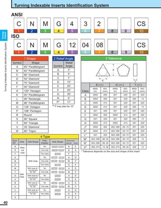
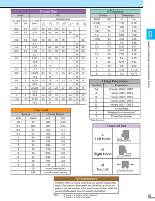

The document provides a comprehensive identification system for turning indexable inserts, detailing various shapes, relief angles, tolerance classes, and chipbreaker styles. It includes ANSI and ISO dimensions, symbols for different insert sizes, and specifications on edge preparation and hand of tool. Various tables and symbols are used to outline the characteristics and classifications relevant to the turning inserts.


