
Recommended
More Related Content
More from fjjseksxckmdme
More from fjjseksxckmdme (20)
Recently uploaded
Recently uploaded (20)
Toro workman md service repair manual
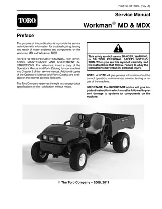
- 1. Part No. 08160SL (Rev. A) Service Manual WorkmanR MD & MDX Preface The purpose of this publication is to provide the service technician with information for troubleshooting, testing and repair of major systems and components on the Workman MD and Workman MDX. REFER TO THE OPERATOR’S MANUAL FOR OPER- ATING, MAINTENANCE AND ADJUSTMENT IN- STRUCTIONS. For reference, insert a copy of the Operator’s Manual and Parts Catalog for your machine into Chapter 2 of this service manual. Additional copies of the Operator’s Manual and Parts Catalog are avail- able on the internet at www.Toro.com. The Toro Company reserves the right to change product specifications or this publication without notice. This safety symbol means DANGER, WARNING, or CAUTION, PERSONAL SAFETY INSTRUC- TION. When you see this symbol, carefully read the instructions that follow. Failure to obey the instructions may result in personal injury. NOTE: A NOTE will give general information about the correct operation, maintenance, service, testing or re- pair of the machine. IMPORTANT: The IMPORTANT notice will give im- portant instructions which must be followed to pre- vent damage to systems or components on the machine. E The Toro Company - - 2008, 2011
- 2. Rev. A Workman MD/MDX Table Of Contents Chapter 1 - - Safety Safety Instructions 1 -- 2 . . . . . . . . . . . . . . . . . . . . . . . . . . Jacking and Other Instructions 1 -- 4 . . . . . . . . . . . . . . . Safety and Instruction Decals 1 -- 6 . . . . . . . . . . . . . . . . Chapter 2 - - Product Records and Maintenance Product Records 2 -- 1 . . . . . . . . . . . . . . . . . . . . . . . . . . . Maintenance 2 -- 1 . . . . . . . . . . . . . . . . . . . . . . . . . . . . . . . Equivalents and Conversions 2 -- 2 . . . . . . . . . . . . . . . . Torque Specifications 2 -- 3 . . . . . . . . . . . . . . . . . . . . . . . Chapter 3 - - Briggs & Stratton Gasoline Engine General Information 3 -- 2 . . . . . . . . . . . . . . . . . . . . . . . . Specifications 3 -- 3 . . . . . . . . . . . . . . . . . . . . . . . . . . . . . . Adjustments 3 -- 4 . . . . . . . . . . . . . . . . . . . . . . . . . . . . . . . Service and Repairs 3 -- 5 . . . . . . . . . . . . . . . . . . . . . . . . Briggs and Stratton Repair Manual for 4--Cycle, V--Twin Cylinder, OHV Head Engines Chapter 4 - - Single Cylinder Gasoline Engine General Information 4 -- 2 . . . . . . . . . . . . . . . . . . . . . . . . Specifications 4 -- 3 . . . . . . . . . . . . . . . . . . . . . . . . . . . . . . Adjustments 4 -- 4 . . . . . . . . . . . . . . . . . . . . . . . . . . . . . . . Service and Repairs 4 -- 5 . . . . . . . . . . . . . . . . . . . . . . . . Kohler Service Manual for COMMAND PRO CS Series Engines Chapter 5 - - Drive Train General Information 5 -- 1 . . . . . . . . . . . . . . . . . . . . . . . . Specifications 5 -- 2 . . . . . . . . . . . . . . . . . . . . . . . . . . . . . . Drive Train Operation 5 -- 3 . . . . . . . . . . . . . . . . . . . . . . . Special Tools 5 -- 6 . . . . . . . . . . . . . . . . . . . . . . . . . . . . . . Adjustments 5 -- 7 . . . . . . . . . . . . . . . . . . . . . . . . . . . . . . . Service and Repairs 5 -- 10 . . . . . . . . . . . . . . . . . . . . . . . Chapter 6 - - Electrical System General Information 6 -- 2 . . . . . . . . . . . . . . . . . . . . . . . . Electrical Schematics 6 -- 2 . . . . . . . . . . . . . . . . . . . . . . . Special Tools 6 -- 3 . . . . . . . . . . . . . . . . . . . . . . . . . . . . . . Troubleshooting 6 -- 5 . . . . . . . . . . . . . . . . . . . . . . . . . . . . Electrical System Quick Checks 6 -- 7 . . . . . . . . . . . . . . Component Testing 6 -- 8 . . . . . . . . . . . . . . . . . . . . . . . . . Service and Repairs 6 -- 18 . . . . . . . . . . . . . . . . . . . . . . . Chapter 7 - - Chassis General Information 7 -- 1 . . . . . . . . . . . . . . . . . . . . . . . . Specifications 7 -- 2 . . . . . . . . . . . . . . . . . . . . . . . . . . . . . . Special Tools 7 -- 2 . . . . . . . . . . . . . . . . . . . . . . . . . . . . . . Troubleshooting 7 -- 3 . . . . . . . . . . . . . . . . . . . . . . . . . . . . Adjustments 7 -- 6 . . . . . . . . . . . . . . . . . . . . . . . . . . . . . . . Service and Repairs 7 -- 9 . . . . . . . . . . . . . . . . . . . . . . . . Chapter 8 - - Electrical Drawings Electrical Schematics 8 -- 3 . . . . . . . . . . . . . . . . . . . . . . . Circuit Diagrams 8 -- 5 . . . . . . . . . . . . . . . . . . . . . . . . . . . Electrical Harness Drawings 8 -- 7 . . . . . . . . . . . . . . . . . Safety Product Records and Maintenance Briggs & Stratton Gasoline Engine Drive Train Electrical System Electrical Drawings Chassis Single Cylinder Gasoline Engine
- 3. Workman MD/MDX Page 1 - - 1 Safety Chapter 1 Safety Table of Contents SAFETY INSTRUCTIONS 2 . . . . . . . . . . . . . . . . . . . . . . Supervisor’s Responsibilities 2 . . . . . . . . . . . . . . . . . Before Operating 2 . . . . . . . . . . . . . . . . . . . . . . . . . . . . While Operating 3 . . . . . . . . . . . . . . . . . . . . . . . . . . . . . Maintenance and Service 3 . . . . . . . . . . . . . . . . . . . . JACKING AND OTHER INSTRUCTIONS 4 . . . . . . . . . Jack Vehicle 4 . . . . . . . . . . . . . . . . . . . . . . . . . . . . . . . . Transport Vehicle 4 . . . . . . . . . . . . . . . . . . . . . . . . . . . Tow Vehicle 4 . . . . . . . . . . . . . . . . . . . . . . . . . . . . . . . . Transaxle Neutral Position 5 . . . . . . . . . . . . . . . . . . . . SAFETY AND INSTRUCTION DECALS 6 . . . . . . . . . . Safety
- 4. Workman MD/MDX Page 1 - - 2 Safety Safety Instructions The Workman MD and MDX series vehicles are de- signed and tested to offer safe service when operated and maintained properly. Although hazard control and accident prevention partially are dependent upon the design and configuration of the machine, these factors are also dependent upon the awareness, concern and proper training of the personnel involved in the opera- tion, transport, maintenance and storage of the ma- chine. Improper use or maintenance of the machine can result in injury or death. Read and understand the contents of the Operator’s Manual before starting and operating the machine. Be- come familiar with all controls and know how to stop it quickly. Additional copies of the Operator’s Manual are available on the internet at www.Toro.com. The safety alert symbol means CAUTION, WARNING or DANGER — “personal safety instruction”. Read and understand the instruction because it has to do with safety. Failure to comply with the instruc- tion may result in personal injury. WARNING To reduce the potential for injury or death, comply with the following safety instructions. WARNING The Workman is an off- -highway vehicle only. It is not designed, equipped or manufactured for use on public streets, roads or highways. Supervisor’s Responsibilities 1. Make sure operators are thoroughly trained and fa- miliar with the Operator’s Manual and all labels on the vehicle. 2. Be sure to establish your own special procedures and work rules for unusual operating conditions (e.g. slopes too steep for vehicle operation). Before Operating 1. Read and understand the contents of the Operator’s Manual and Operator’s DVD before starting and operat- ing the vehicle. Become familiar with the controls and know how to stop the vehicle and engine quickly. Addi- tional copies of the Operator’s Manual are available on the internet at www.Toro.com. 2. Keep all shields, safety devices and decals in place. If a shield, safety device or decal is defective, illegible or damaged, repair or replace it before operating the ve- hicle. Also, tighten any loose nuts, bolts or screws to en- sure vehicle is in safe operating condition. 3. Since fuel used in Workman vehicles is highly flam- mable, handle it carefully: A. Store fuel in containers specifically designed for this purpose. B. Do not remove vehicle fuel tank cap while engine is hot or running. C. Do not smoke while handling fuel. D. Fill fuel tank outdoors and only to within an inch of the top of the tank, not the filler neck. Do not overfill the fuel tank. E. Clean up any spilled fuel.
- 5. Workman MD/MDX Page 1 - - 3 Safety While Operating 1. Sit on the operator seat when starting and operating the vehicle. 2. Before starting the engine: A. Sit on operator’s seat and apply the parking brake. B. Turn ignition key to ON. C. Depress accelerator pedalto startengine anden- gage drive system. 3. Do not run engine in a confined area without ade- quate ventilation. Exhaust fumes are hazardous and could possibly be deadly. 4. Do not touch engine, muffler or exhaust pipe while engine isrunning orsoon afteritisstopped.Theseareas could be hot enough to cause burns. 5. Before getting off the seat: A. Stop movement of the vehicle. B. Turn ignition key to OFF and wait for all move- ment to stop. C. Remove key from ignition switch. D. Apply parking brake. E. Do not park on slopes unless wheels are chocked or blocked. Maintenance and Service 1. Before servicing or making adjustments, turn all ac- cessories off, release pressure from accelerator pedal, allow engine to stop, set parking brake and remove key from the ignition switch. 2. Make sure vehicle is in safe operating condition by keeping all nuts, bolts and screws tight. 3. Never store the vehicle or fuel container inside where there is an open flame, such as near a water heat- er or furnace. 4. If major repairs are ever needed or assistance is de- sired, contact an Authorized Toro Distributor. 5. To reduce potential fire hazard, keep engine area free of excessive grease, grass, leaves and dirt. 6. If engine must be running to perform maintenance or an adjustment, keep clothing, hands, feet and other parts of the body away from moving parts. Keep by- standers away. 7. Do not overspeed the engine by changing governor setting. To assure safety and accuracy, check maximum engine speed. 8. Shut engine off before checking or adding oil to the engine crankcase. 9. Disconnect battery before servicing the vehicle. Dis- connect negative (--) battery cable first and positive (+) cable last. If battery voltage is required for troubleshoot- ing or test procedures, temporarily connect the battery. Reconnect positive (+) cable first and negative (--) cable last. 10.Battery acid is poisonous and can cause burns. Avoid contact with skin, eyes and clothing. Protect your face, eyes and clothing when working with a battery. 11.Battery gases can explode. Keep cigarettes, sparks and flames away from the battery. 12.To assure optimum performance and continued safety of the vehicle, use genuine Toro replacement parts and accessories. Replacement parts and acces- sories made by other manufacturers may result in non- conformance with safety standards, and the warranty may be voided. 13.When raising the vehicle to change tires or to per- form other service, use correct blocks, hoists and jacks. Makesurevehicleisparkedona solidlevelsurfacesuch as a concrete floor. Prior to raising the vehicle, remove any attachments that may interfere with the safe and proper raising of the vehicle. Always chock or block wheels. Use appropriate jack stands to support the raised vehicle. If the vehicle is not properly supported by jack stands, the vehicle may move or fall, which may re- sult in personal injury (see Jacking Instructions in this section). Safety
- 6. Workman MD/MDX Page 1 - - 4 Safety Jacking and Other Instructions Jack Vehicle DANGER POTENTIAL HAZARD • A vehicle that is not properly supported may become unstable. WHAT CAN HAPPEN • The vehicle may move or fall. Personal injury or damage to the machine may result. HOW TO AVOID THE HAZARD • Make sure vehicle is parked on a solid level surface, such as a concrete floor. • Make sure engine is off and key is removed from the ignition switch before getting off the vehicle. • Before raising the vehicle, remove any attachments that may interfere with the safe and proper raising of the vehicle. • Always chock or block wheels to prevent the vehicle from rolling. • Do not start vehicle while it is on jack stands without placing transaxle in neutral. • Make sure proper hoists, jacks and jack stands are used to raise and support the vehicle. Jacking Locations 1. Jack front of the vehicle on the front of the frame and behind the towing tongue (Fig. 1). 2. Jack rearofthevehicle undereach rearaxle tube.Do not jack vehicle below the transaxle case (Fig. 2). 1. Front frame 2. Towing tongue Figure 1 1 2 1. Transaxle case 2. Axle tube Figure 2 2 1 Transport Vehicle When moving the vehicle long distances, use a trailer or flatbed truck. Make sure vehicle is secured to the trailer properly. Refer to Operator’s Manual for transport infor- mation. Tow Vehicle IMPORTANT: Frequent or long distance towing of the Workman is not recommended. In case of emergency, the vehicle can be towed for a short distance. Refer to Operator’s Manual for towing information. IMPORTANT: If vehicle is towed, make sure that ignition switch is in the OFF position and key is re- moved from switch.
- 7. Workman MD/MDX Page 1 - - 5 Safety Transaxle Neutral Position When performing routine maintenance and/or engine testing, the transaxle must be shifted into the neutral position. 1. Park machine on a level surface, stop engine, set parking brake and remove key from the ignition switch. 2. Move shift lever to the neutral position (Fig. 3). 3. Make sure transaxle is in the neutral position by ro- tating the driven clutch. The tires should not rotate. If tire rotation does occur, see Adjust Shift Cables in the Ad- justment section of Chapter 5 -- Drive Train. 1. Shift lever (in neutral) 2. Forward position 3. Reverse position Figure 3 1 3 2 Safety
- 8. Workman MD/MDX Page 1 - - 6 Safety Safety and Instruction Decals Numerous safety and instruction decals are affixed to your Workman. If any decal becomes illegible or dam- aged, install a new decal. Part numbers are listed in the Parts Catalog. Order replacement decals from your Au- thorized Toro Distributor.
- 9. Workman MD/MDX Page 2 - - 1 Product Records and Maintenance Chapter 2 Product Records and Maintenance Table of Contents PRODUCT RECORDS 1 . . . . . . . . . . . . . . . . . . . . . . . . . MAINTENANCE 1 . . . . . . . . . . . . . . . . . . . . . . . . . . . . . . . EQUIVALENTS AND CONVERSIONS 2 . . . . . . . . . . . Decimal and Millimeter Equivalents 2 . . . . . . . . . . . . U.S. to Metric Conversions 2 . . . . . . . . . . . . . . . . . . . TORQUE SPECIFICATIONS 3 . . . . . . . . . . . . . . . . . . . . Fastener Identification 3 . . . . . . . . . . . . . . . . . . . . . . . Standard Torque for Dry, Zinc Plated and Steel Fasteners (Inch Series). 4 . . . . . . . . . . . . . . . Standard Torque for Dry, Zinc Plated and Steel Fasteners (Metric Fasteners). 5 . . . . . . . . . . Other Torque Specifications 6 . . . . . . . . . . . . . . . . . . Conversion Factors 6 . . . . . . . . . . . . . . . . . . . . . . . . . . Product Records Insert Operator’s Manual and Parts Catalog for your Workman at the end of this chapter. Additionally, if any optional equipment or accessories have been installed to your machine, insert the Installation Instructions, Op- erator’s Manuals and Parts Catalogs for those options at the end of this chapter. Maintenance Maintenance procedures and recommended service in- tervals for your Workman are covered in the Operator’s Manual. Refer to that publication when performing regu- lar equipment maintenance. Product Records and Maintenance
- 10. 0.09375 Workman MD/MDX Page 2 - - 2 Product Records and Maintenance Equivalents and Conversions
- 11. Workman MD/MDX Page 2 - - 3 Product Records and Maintenance Torque Specifications Recommended fastener torque values are listed in the following tables. For critical applications, as determined by Toro, either the recommended torque or a torque that is unique to the application is clearly identified and spe- cified in this Service Manual. These Torque Specifications for the installation and tightening of fasteners shall apply to all fasteners which do not have a specific requirement identified in this Ser- vice Manual. The following factors shall be considered when applying torque: cleanliness of the fastener, use of a thread sealant (e.g. Loctite), degree of lubrication on the fastener, presence of a prevailing torque feature, hardness of the surface underneath the fastener’s head or similar condition which affects the installation. As noted in the following tables, torque values should be reduced by 25% for lubricated fasteners to achieve the similar stress as a dry fastener. Torque values may also have to be reduced when the fastener is threaded into aluminum or brass. The specific torque value should be determined based on the aluminum or brass material strength, fastener size, length of thread en- gagement, etc. The standard method of verifying torque shall be per- formed by marking a line on the fastener (head or nut) and mating part, then back off fastener 1/4 of a turn. Measure the torque required to tighten the fastener until the lines match up. Fastener Identification Figure 1 Grade 1 Grade 5 Grade 8 Inch Series Bolts and Screws Figure 2 Class 8.8 Class 10.9 Metric Bolts and Screws Product Records and Maintenance
- 12. Workman MD/MDX Page 2 - - 4 Product Records and Maintenance Standard Torque for Dry, Zinc Plated and Steel Fasteners (Inch Series) Thread Size Grade 1, 5 & 8 with Thin Height Nuts SAE Grade 1 Bolts, Screws, Studs & Sems with Regular Height Nuts (SAE J995 Grade 2 or Stronger Nuts) SAE Grade 5 Bolts, Screws, Studs & Sems with Regular Height Nuts (SAE J995 Grade 2 or Stronger Nuts) SAE Grade 8 Bolts, Screws, Studs & Sems with Regular Height Nuts (SAE J995 Grade 5 or Stronger Nuts) in- -lb in- -lb N- -cm in- -lb N- -cm in- -lb N- -cm # 6 -- 32 UNC 10 + 2 13 + 2 147 + 23 15 + 2 170 + 20 23 + 2 260 + 20 # 6 -- 40 UNF 10 + 2 13 + 2 147 + 23 17 + 2 190 + 20 25 + 2 280 + 20 # 8 -- 32 UNC 13 + 2 25 + 5 282 + 30 29 + 3 330 + 30 41 + 4 460 + 45 # 8 -- 36 UNF 13 + 2 25 + 5 282 + 30 31 + 3 350 + 30 43 + 4 485 + 45 # 10 -- 24 UNC 18 + 2 30 + 5 339 + 56 42 + 4 475 + 45 60 + 6 675 + 70 # 10 -- 32 UNF 18 + 2 30 + 5 339 + 56 48 + 4 540 + 45 68 + 6 765 + 70 1/4 -- 20 UNC 48 + 7 53 + 7 599 + 79 100 + 10 1125 + 100 140 + 15 1580 + 170 1/4 -- 28 UNF 53 + 7 65 + 10 734 + 113 115 + 10 1300 + 100 160 + 15 1800 + 170 5/16 -- 18 UNC 115 + 15 105 + 17 1186 + 169 200 + 25 2250 + 280 300 + 30 3390 + 340 5/16 -- 24 UNF 138 + 17 128 + 17 1446 + 192 225 + 25 2540 + 280 325 + 30 3670 + 340 ft- -lb ft- -lb N- -m ft- -lb N- -m ft- -lb N- -m 3/8 -- 16 UNC 16 + 2 16 + 2 22 + 3 30 + 3 41 + 4 43 + 4 58 + 5 3/8 -- 24 UNF 17 + 2 18 + 2 24 + 3 35 + 3 47 + 4 50 + 4 68 + 5 7/16 -- 14 UNC 27 + 3 27 + 3 37 + 4 50 + 5 68 + 7 70 + 7 95 + 9 7/16 -- 20 UNF 29 + 3 29 + 3 39 + 4 55 + 5 75 + 7 77 + 7 104 + 9 1/2 -- 13 UNC 30 + 3 48 + 7 65 + 9 75 + 8 102 + 11 105 + 10 142 + 14 1/2 -- 20 UNF 32 + 3 53 + 7 72 + 9 85 + 8 115 + 11 120 + 10 163 + 14 5/8 -- 11 UNC 65 + 10 88 + 12 119 + 16 150 + 15 203 + 20 210 + 20 285 + 27 5/8 -- 18 UNF 75 + 10 95 + 15 129 + 20 170 + 15 230 + 20 240 + 20 325 + 27 3/4 -- 10 UNC 93 + 12 140 + 20 190 + 27 265 + 25 359 + 34 375 + 35 508 + 47 3/4 -- 16 UNF 115 + 15 165 + 25 224 + 34 300 + 25 407 + 34 420 + 35 569 + 47 7/8 -- 9 UNC 140 + 20 225 + 25 305 + 34 430 + 45 583 + 61 600 + 60 813 + 81 7/8 -- 14 UNF 155 + 25 260 + 30 353 + 41 475 + 45 644 + 61 660 + 60 895 + 81 NOTE: Reduce torque values listed in the table above by 25% for lubricated fasteners. Lubricated fasteners are defined as threads coated with a lubricant such as oil, graphite or thread sealant such as Loctite. NOTE: Torque values may have to be reduced when installing fasteners into threaded aluminum or brass. The specific torque value should be determined based on the fastener size, the aluminum or base material strength, length of thread engagement, etc. NOTE: The nominal torque values listed above for Grade 5 and 8 fasteners are based on 75% of the mini- mum proof load specified in SAE J429. The tolerance is approximately + 10% of the nominal torque value. Thin height nuts include jam nuts.
- 13. Workman MD/MDX Page 2 - - 5 Product Records and Maintenance Standard Torque for Dry, Zinc Plated and Steel Fasteners (Metric Fasteners) Thread Size Class 8.8 Bolts, Screws and Studs with Regular Height Nuts Class 10.9 Bolts, Screws and Studs with Regular Height Nuts Thread Size Regular Height Nuts (Class 8 or Stronger Nuts) Regular Height Nuts (Class 10 or Stronger Nuts) M5 X 0.8 57 + 5 in--lb 640 + 60 N--cm 78 + 7 in--lb 885 + 80 N--cm M6 X 1.0 96 + 9 in--lb 1018 + 100 N--cm 133 + 13 in--lb 1500 + 150 N--cm M8 X 1.25 19 + 2 ft--lb 26 + 3 N--m 27 + 2 ft--lb 36 + 3 N--m M10 X 1.5 38 + 4 ft--lb 52 + 5 N--m 53 + 5 ft--lb 72 + 7 N--m M12 X 1.75 66 + 7 ft--lb 90 + 10 N--m 92 + 9 ft--lb 125 + 12 N--m M16 X 2.0 166 + 15 ft--lb 225 + 20 N--m 229 + 22 ft--lb 310 + 30 N--m M20 X 2.5 325 + 33 ft--lb 440 + 45 N--m 450 + 37 ft--lb 610 + 50 N--m NOTE: Reduce torque values listed in the table above by 25% for lubricated fasteners. Lubricated fasteners are defined as threads coated with a lubricant such as oil, graphite or thread sealant such as Loctite. NOTE: Torque values may have to be reduced when installing fasteners into threaded aluminum or brass. The specific torque value should be determined based on the fastener size, the aluminum or base material strength, length of thread engagement, etc. NOTE: The nominal torque values listed above are based on 75% of the minimum proof load specified in SAE J1199. The tolerance is approximately + 10% of the nominal torque value. Product Records and Maintenance
- 14. Workman MD/MDX Page 2 - - 6 Product Records and Maintenance Other Torque Specifications SAE Grade 8 Steel Set Screws Thread Size Recommended Torque Thread Size Square Head Hex Socket 1/4 -- 20 UNC 140 + 20 in--lb 73 + 12 in--lb 5/16 -- 18 UNC 215 + 35 in--lb 145 + 20 in--lb 3/8 -- 16 UNC 35 + 10 ft--lb 18 + 3 ft--lb 1/2 -- 13 UNC 75 + 15 ft--lb 50 + 10 ft--lb Thread Cutting Screws (Zinc Plated Steel) Type 1, Type 23 or Type F Thread Size Baseline Torque* No. 6 -- 32 UNC 20 + 5 in--lb No. 8 -- 32 UNC 30 + 5 in--lb No. 10 -- 24 UNC 38 + 7 in--lb 1/4 -- 20 UNC 85 + 15 in--lb 5/16 -- 18 UNC 110 + 20 in--lb 3/8 -- 16 UNC 200 + 100 in--lb Wheel Bolts and Lug Nuts Thread Size Recommended Torque** 7/16 -- 20 UNF Grade 5 65 + 10 ft--lb 88 + 14 N--m 1/2 -- 20 UNF Grade 5 80 + 10 ft--lb 108 + 14 N--m M12 X 1.25 Class 8.8 80 + 10 ft--lb 108 + 14 N--m M12 X 1.5 Class 8.8 80 + 10 ft--lb 108 + 14 N--m ** For steel wheels and non--lubricated fasteners. Thread Cutting Screws (Zinc Plated Steel) Thread Size Threads per Inch Baseline Torque* Size Type A Type B Baseline Torque* No. 6 18 20 20 + 5 in--lb No. 8 15 18 30 + 5 in--lb No. 10 12 16 38 + 7 in--lb No. 12 11 14 85 + 15 in--lb *Hole size,materialstrength,materialthickness and fin- ish must be considered when determining specific torque values. All torque values are based on non--lubri- cated fasteners. Conversion Factors in- -lb X 11.2985 = N- -cm N- -cm X 0.08851 = in- -lb ft- -lb X 1.3558 = N- -m N- -m X 0.7376 = ft- -lb
- 15. Workman MDX Page 3 - - 1 Briggs & Stratton Gasoline Engine Chapter 3 Briggs & Stratton Gasoline Engine Table of Contents GENERAL INFORMATION 2 . . . . . . . . . . . . . . . . . . . . . Operator’s Manual 2 . . . . . . . . . . . . . . . . . . . . . . . . . . SPECIFICATIONS 3 . . . . . . . . . . . . . . . . . . . . . . . . . . . . . ADJUSTMENTS 4 . . . . . . . . . . . . . . . . . . . . . . . . . . . . . . Adjust Throttle Cable 4 . . . . . . . . . . . . . . . . . . . . . . . . SERVICE AND REPAIRS 5 . . . . . . . . . . . . . . . . . . . . . . Cooling System 5 . . . . . . . . . . . . . . . . . . . . . . . . . . . . . Air Cleaner 6 . . . . . . . . . . . . . . . . . . . . . . . . . . . . . . . . . Exhaust System 8 . . . . . . . . . . . . . . . . . . . . . . . . . . . . Fuel Tank 10 . . . . . . . . . . . . . . . . . . . . . . . . . . . . . . . . . Oil Filter Assembly 12 . . . . . . . . . . . . . . . . . . . . . . . . . Engine 14 . . . . . . . . . . . . . . . . . . . . . . . . . . . . . . . . . . . . Engine Removal 15 . . . . . . . . . . . . . . . . . . . . . . . . . . Engine Installation 16 . . . . . . . . . . . . . . . . . . . . . . . . BRIGGS & STRATTON REPAIR MANUAL FOR 4--CYCLE, V--TWIN CYLINDER, OHV HEAD EN- GINES Briggs & Stratton Gasoline Engine
- 16. Workman MDX Page 3 - - 2 Briggs & Stratton Gasoline Engine General Information This Chapter gives information about specifications, maintenance, troubleshooting, testing and repair of the V--twin cylinder, gasoline engine used in the Workman MDX. Most repairs and adjustments require tools which are commonly available in many service shops. Special tools are described in the Briggs & Stratton Repair Manual for 4--Cycle, V--Twin Cylinder, OHV Head En- gines.Theuseofsomespecialized testequipmentisex- plained. However, the cost of the test equipment and the specialized nature of some repairs may dictate that the work be done at an engine repair facility. Service and repair parts for Briggs & Stratton engines are supplied through your local Toro distributor. If no parts list is available, be sure to provide your distributor with the Toro model and serial number. Operator’s Manual The Operator’s Manual provides information regarding the operation, general maintenance and maintenance intervals for your Workman MDX vehicle. Refer to the Operator’s Manual for additional information when ser- vicing the machine.
- 17. Thank you very much for your reading. Please Click Here. Then Get COMPLETE MANUAL. NO WAITING NOTE: If there is no response to click on the link above, please download the PDF document first and then click on it.
- 18. Workman MDX Page 3 - - 3 Briggs & Stratton Gasoline Engine Specifications Item Description Make / Designation Briggs and Stratton, 4--cycle, V--Twin Cylinder, OHV, Air Cooled, Gasoline Engine -- Model 303440 Bore x Stroke 2.68” x 2.60” (68 mm x 66 mm) Total Displacement 29.3 in3 (480 cc) Governor Mechanical Governor Carburetor Float Feed, Single Barrel Fuel Pump Pulsating Crankcase Vacuum Fuel Unleaded, regular grade gasoline Fuel Tank Capacity 7.0 U.S. gal (26.5 l) Lubrication System Pressure Lubrication, Gear Driven Geroter Oil Pump Crankcase Oil Capacity 1.75 U.S. qt (1.66 l) with new filter Engine Oil See Operator’s Manual Ignition System Flywheel magneto, twin electronic armatures Spark Plugs Champion RC 12YC (or equivalent) Spark Plug Gap 0.030” (0.76 mm) Starter/Generator 10.5 VDC 100 Amps/14 VDC and 23 Amps Dry Weight (approximate) 72 lb (32.4 kg) Briggs & Stratton Gasoline Engine
- 19. Workman MDX Page 3 - - 4 Briggs & Stratton Gasoline Engine Adjustments Adjust Throttle Cable NOTE: The Workman MDX is equipped with an engine governor. Refer to the Briggs & Stratton Repair Manual at the end of this chapter for governor information on these machines. Depressing the accelerator pedal rotates the engine governor bellcrank which tensions the main governor spring to increase engine speed. Releasing the acceler- ator pedal decreases governor spring tension to reduce engine speed. 1. Park machine on a level surface, stop engine, en- gage parking brake and remove key from the ignition switch. 2. Lift cargo box and prop with rod to gain access to the engine. 3. When the accelerator pedal is fully depressed the engine governor bellcrank mechanism should have a gap from 0.030” to 0.080” (0.8 to 2.0 mm) (Fig. 2). If nec- essary, adjust jam nuts on accelerator cable so that gap is correct. 4. After throttle cable adjustment is correct, lower and secure cargo box. Figure 1 1. Throttle cable 2. Governor bellcrank 1 2 ACCELERATOR PEDAL RELEASED Figure 2 1. Throttle cable 2. Governor bellcrank 3. Gap 3 1 2 ACCELERATOR PEDAL DEPRESSED
- 20. Workman MDX Page 3 - - 5 Briggs & Stratton Gasoline Engine Service and Repairs Cooling System To ensure proper engine cooling, make sure the grass screen, cooling fins and other external surfaces of the engine are kept clean at all times. NOTE: Perform this maintenance procedure at the in- terval specified in the Operator’s Manual. IMPORTANT: The engine that powers the Workman MDX is air- -cooled. Operating the engine with dirty or plugged cooling fins or a plugged or dirty blower housing will result in engine overheating and dam- age. 1. Park machine on a level surface, stop engine, en- gage parking brake and remove key from the ignition switch. 2. Raise cargo box and support with prop rod. 3. Carefully remove spark plug wires from the spark plugs to prevent the engine from starting unexpectedly. IMPORTANT: Never clean engine with pressurized water. Water could enter and contaminate the fuel system. 4. Clean cooling fins on both cylinder heads (Fig. 3). 5. Clean rotating screen and blower housing of dirt and debris. 6. If necessary remove rotating screen and blower housing fromenginefor morethorough enginecleaning. IMPORTANT: Never operate engine without the ro- tating screen and blower housing installed. Over- heating and engine damage will result. 7. Make sure rotating screen and blower housing are properly installed to the engine if removed. 8. Attach spark plug wires to spark plugs. 9. Lower and secure cargo box. Figure 3 1. Cylinder head cooling fins 1 1 Figure 4 1. Rotating screen 2. Blower housing 1 2 Briggs & Stratton Gasoline Engine