Downloaded 20 times


![21
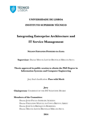
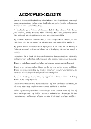
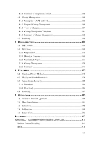
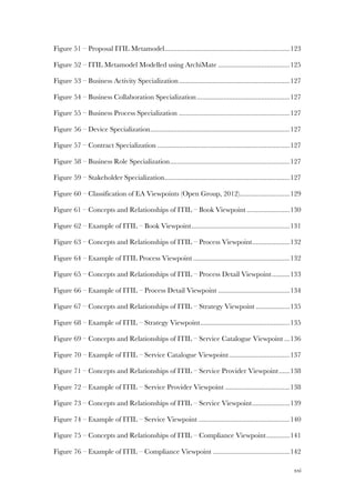
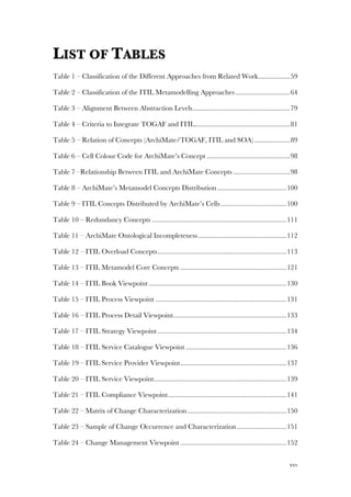
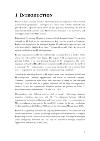
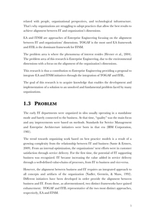
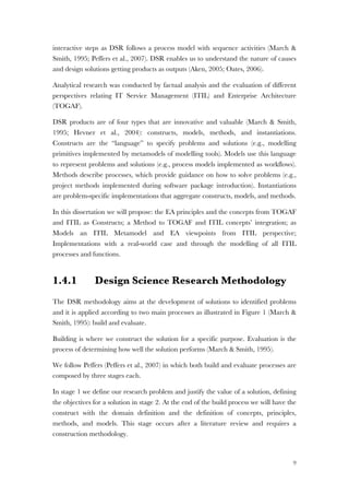
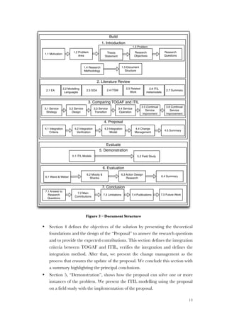
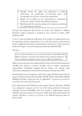
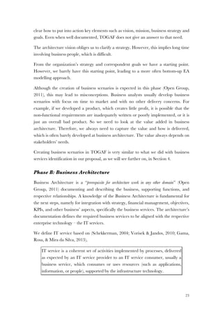
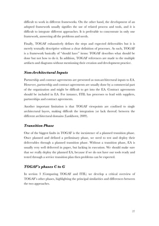
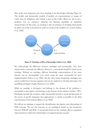
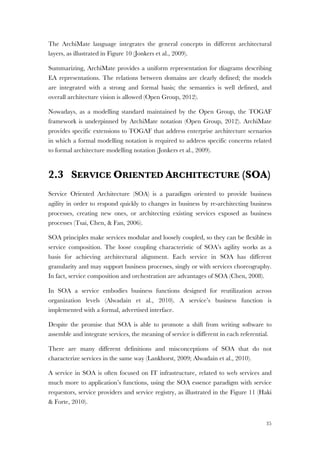
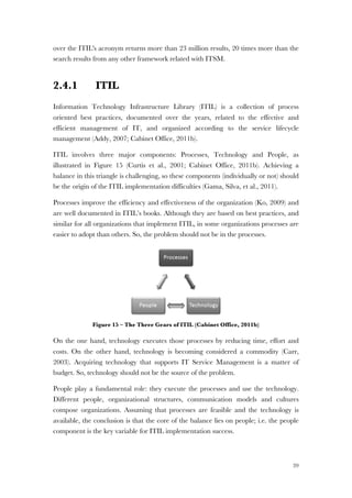
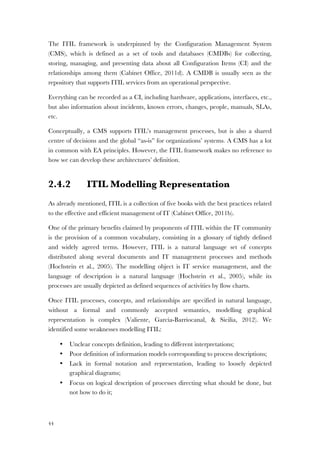
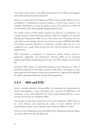
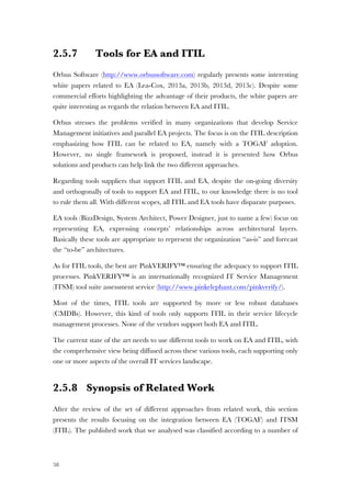
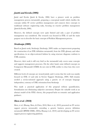
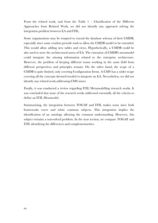
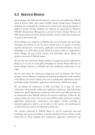
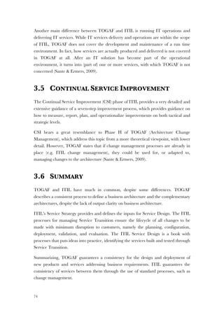
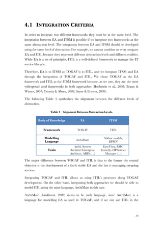
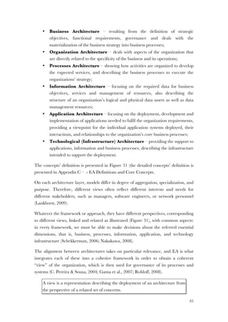
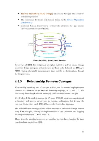
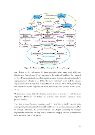
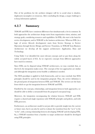
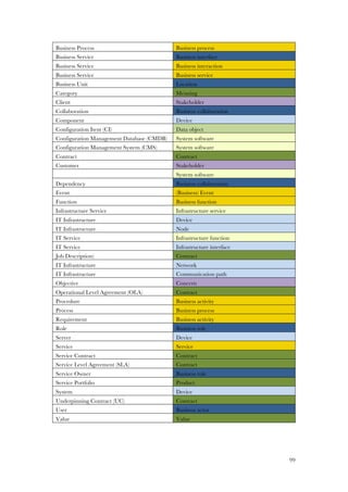
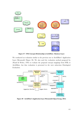
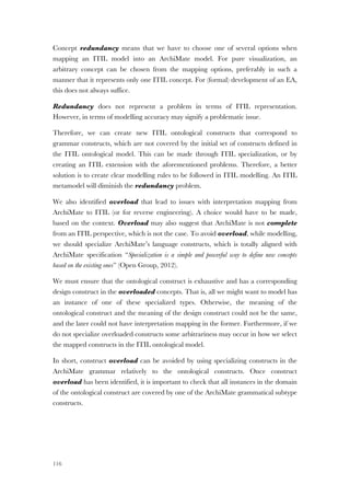
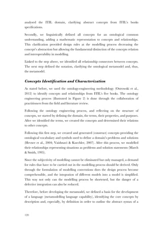
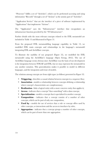
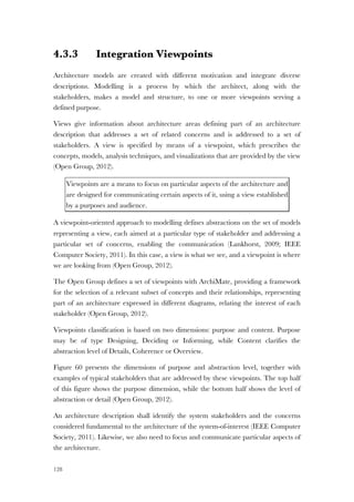
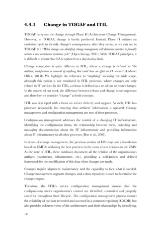
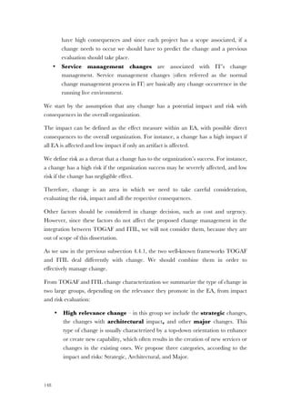
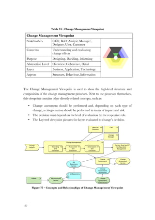
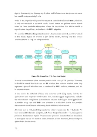
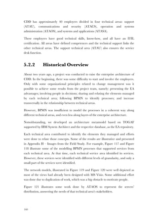
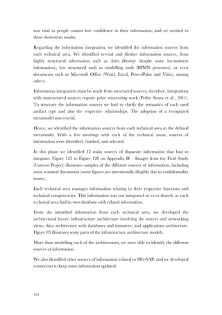
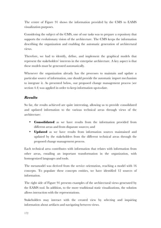
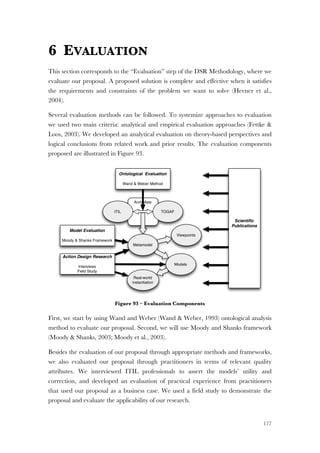
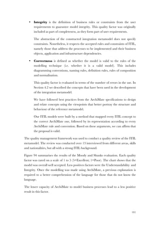
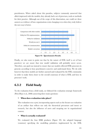
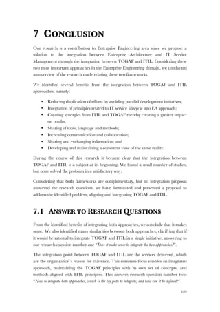
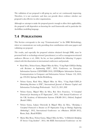
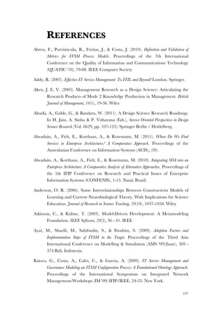
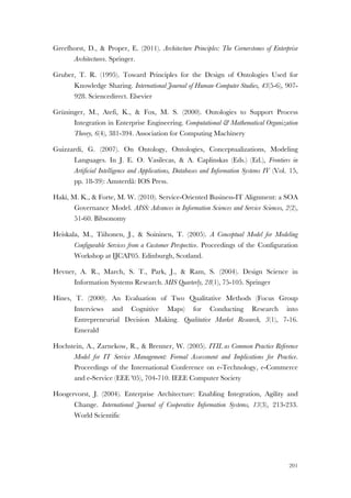
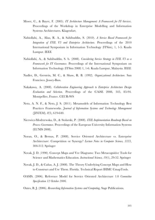
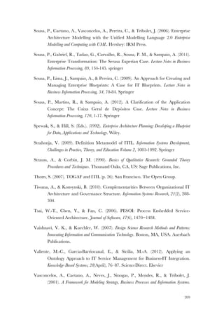
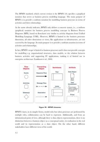
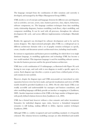
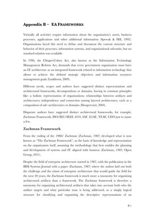
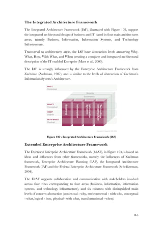
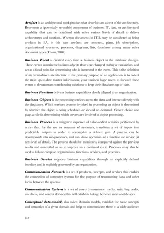
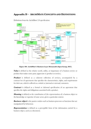
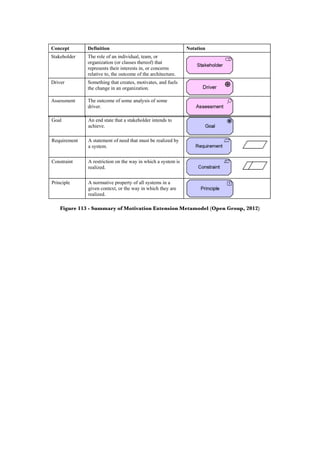
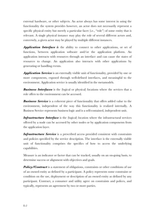
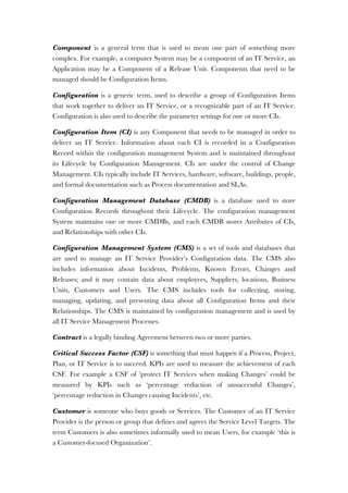
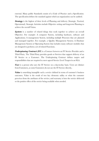
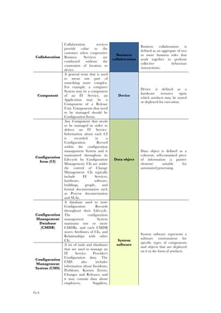
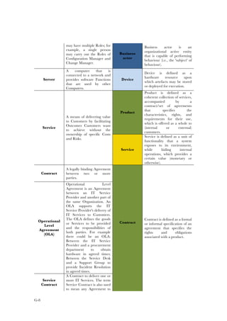
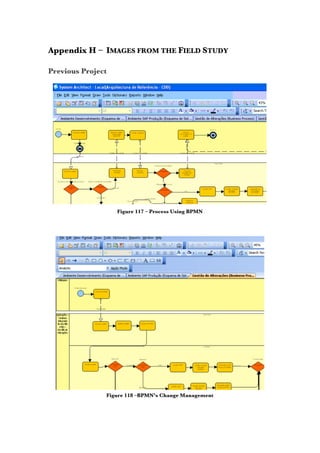
Figure 6 – TOGAF ADM Development Process (Open Group, 2011)
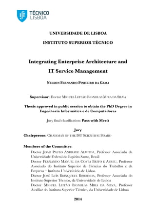
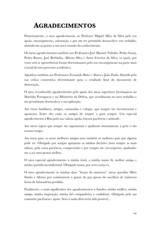
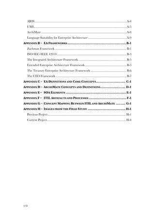
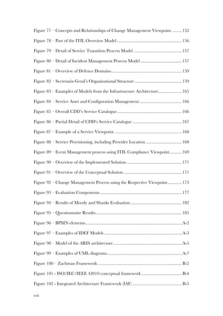
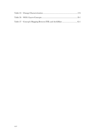
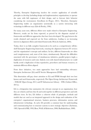
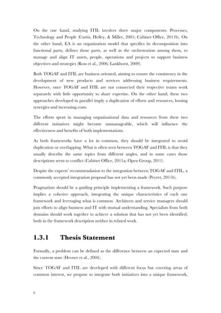
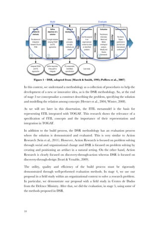
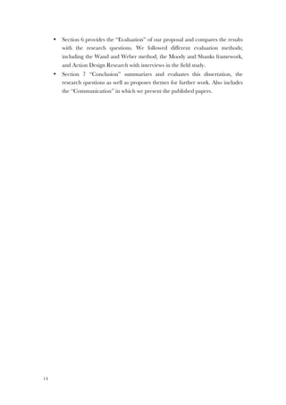
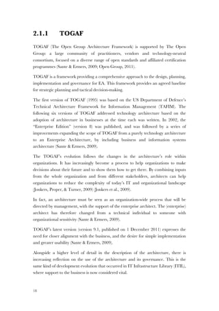
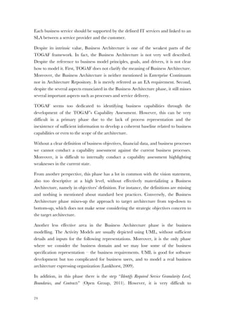
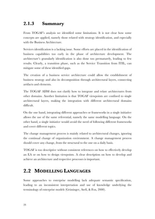
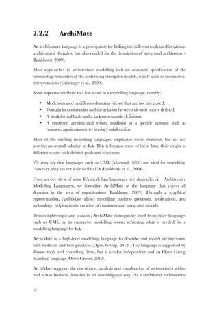
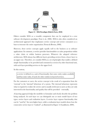
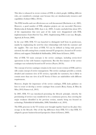
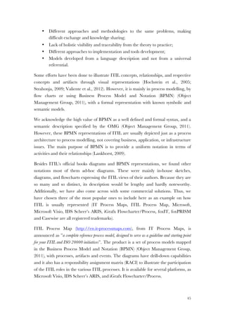
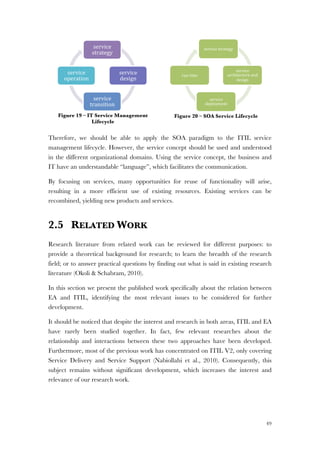
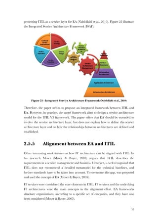
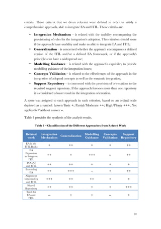
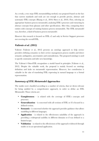
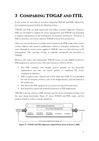
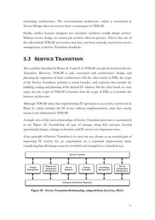
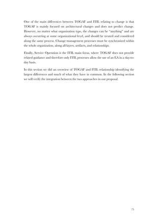
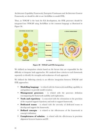
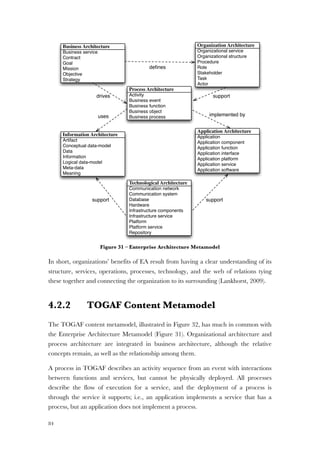
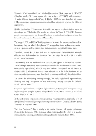
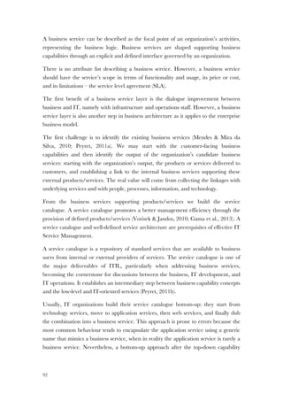
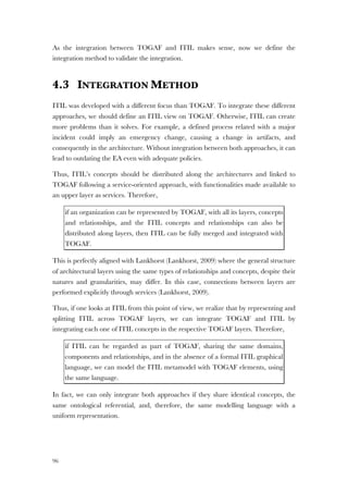
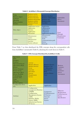
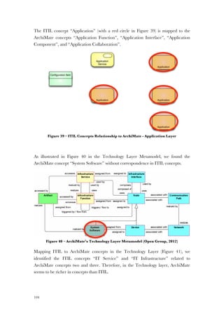
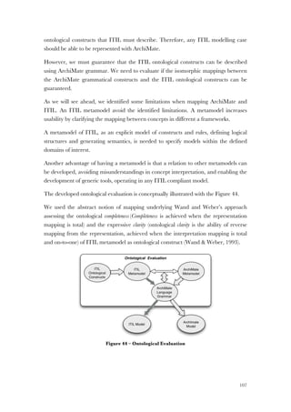
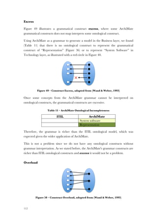
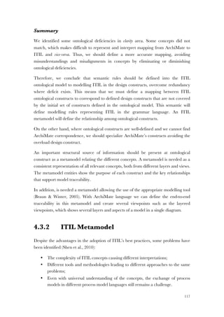
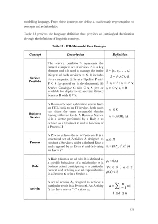
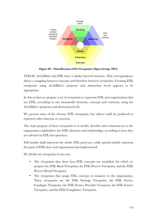
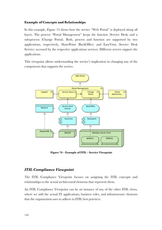
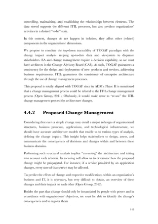
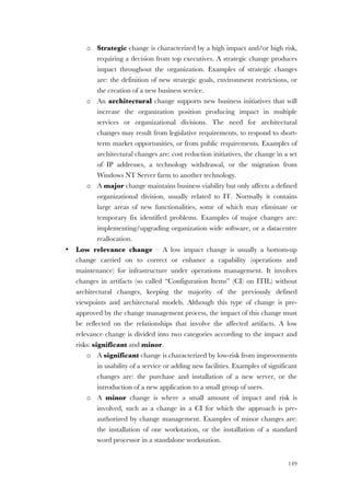
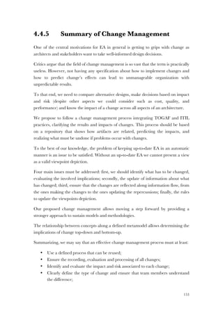
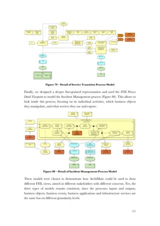
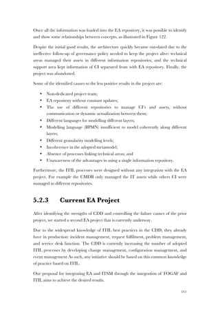
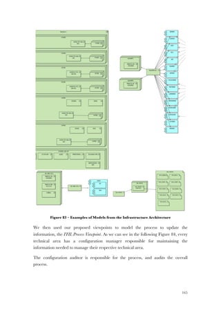
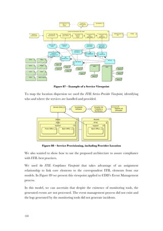
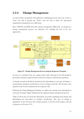
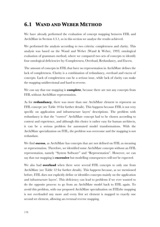
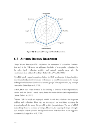
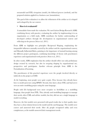
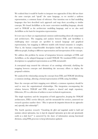
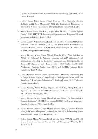
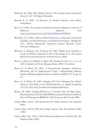
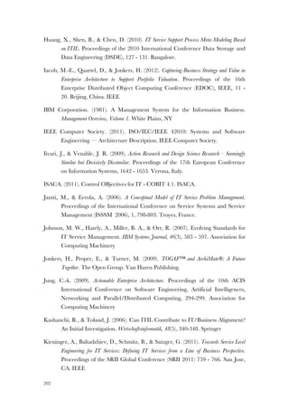
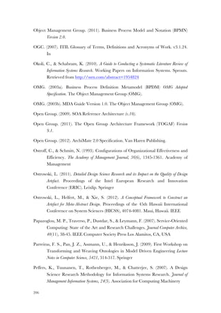
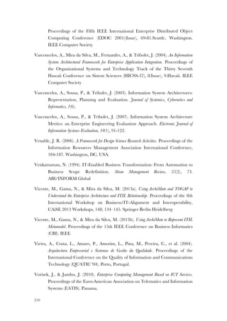
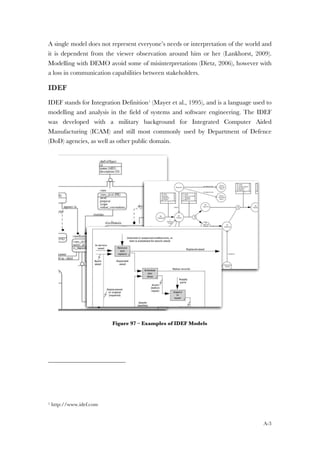
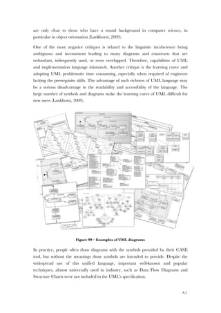
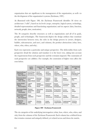
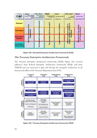
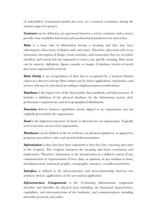
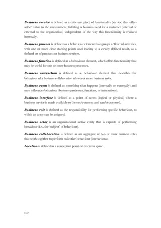
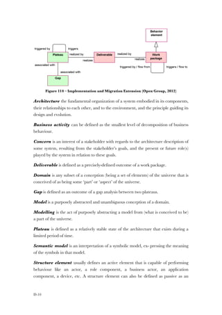
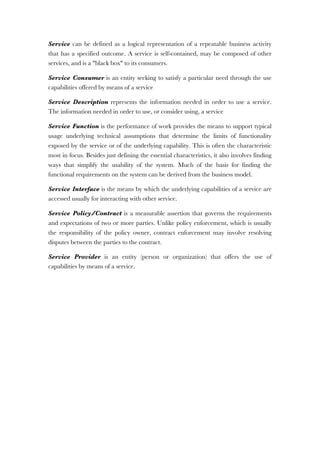
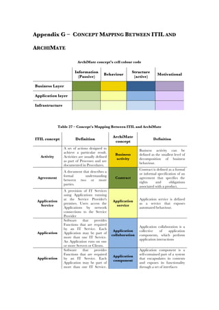
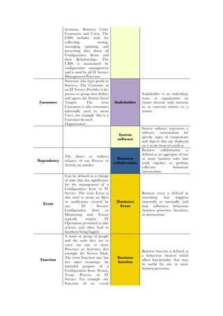
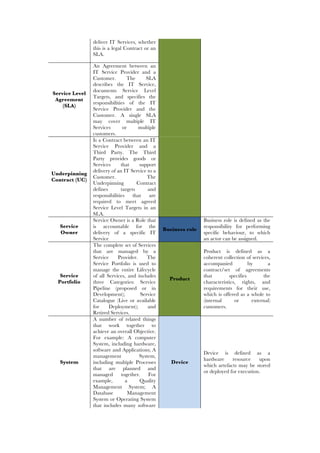
The architecture views, and corresponding viewpoints, as illustrated with Figure 7, fall
into the following categories (Open Group, 2011):
• Business Architecture views, that address the concerns of the stakeholders and
describe the flows of business information between people and business
processes (e.g. people, process, function, business information, usability,
performance).
• Information Systems Architecture views, comprising Data Architecture views
and Applications Architecture views, addressing the concerns of the database
designers, administrators, and software engineers. They focus on how the
system is implemented from the perspective of different types of engineers
(security, software, data, computing components, communications), and how
that affects its properties. Systems and software engineers are typically
concerned with modifiability, re-usability, and availability of other services.
• Technology Architecture views addressing the concerns of the acquirers,
operators, communications engineers, administrators, and managers of the
system.
• Composite views addressing other type of concerns not covered in the
previews views.
www.via-nova-architectura.org March 2007 3
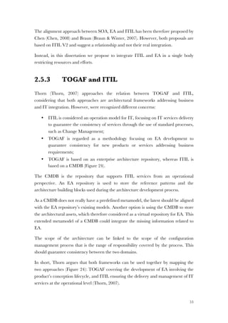
Central to the discussion in this paper is TOGAF’s Architecture Development Method (ADM).
The framework considers an overall Enterprise Architecture as composed of a set of closely in-
terrelated Architectures: Business Architecture, Information Systems Architecture (comprising
Data Architecture and Application Architecture), and Technology (IT) Architecture. ADM is con-
sidered to be the core of TOGAF, and consists of a stepwise cyclic iterative approach for the
development of the overall enterprise architecture (Figure 2).
Figure 2. TOGAF ADM development process [The Open Group, 2006].](https://image.slidesharecdn.com/79aacb86-a093-4053-9c93-f4c52ac3e033-160803192221/85/Thesis-Nelson-Gama-Integrating-EA-and-ITSM-49-320.jpg)
![22
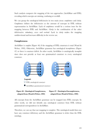
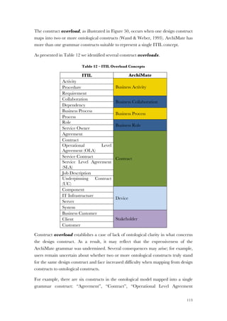
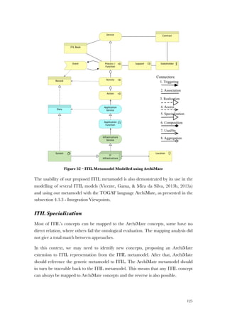
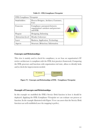
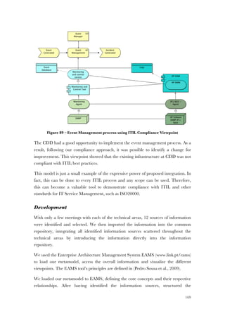
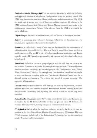
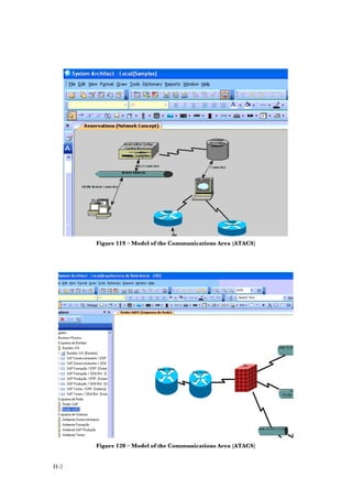
Figure 7 – Views in the TOGAF ADM (Open Group, 2011)
2.1.2 Critical Analysis
The ADM (Figure 6) is the core method of TOGAF (Open Group, 2011) describing
the lifecycle of organization architecture through a cycle of phases for which we
developed the following critical analysis.
Phase A: Architecture Vision
The Architecture Vision’s objectives are the development of a high-level vision of
capabilities and the delivery of business value. Despite all concerns considered in
architecture vision, in practice, when we develop an enterprise architecture it is not
www.via-nova-architectura.org March 2007 5
Figure 3. Views in the TOGAF ADM development process [The Open Group, 2006].
Enterprise Modelling
Modelling languages are an essential instrument for the description and communication of ar-
chitectures, and languages and tools have evolved more or less “hand in hand”. In some cases
methodologies and frameworks have grown around and are supplied together with architecture
support tools, for instance in the case of UML and Rational, EPCs and ARIS [Scheer, 1994],
and Testbed [Eertink et al., 1999]. In other cases, tool vendors have strived to endow their
tools with new functionality in order to support frameworks or other modelling notations such
as UML [Object Management Group, 2003] or the IDEF family [IDEF, 1993], besides their own
proprietary notations (e.g., ARIS, System Architect). Languages and modelling notations are at
the core of all these architecture support packages.
Most languages mentioned provide concepts to model specific domains, e.g., business proc-
esses or software architectures, but rarely do they model the high-level relationships between
these different domains. In current practice, architectural descriptions are made for the differ-
ent domains. Although, to a certain extent, modelling support within each of these domains is
available, well-described concepts to describe the relationships between the domains are al-
most completely missing. Such concepts are essential to tackle the problems of business–IT
alignment and architecture optimization in a systematic way.](https://image.slidesharecdn.com/79aacb86-a093-4053-9c93-f4c52ac3e033-160803192221/85/Thesis-Nelson-Gama-Integrating-EA-and-ITSM-50-320.jpg)

![51
business processes support the business strategy nor how services are linked to
applications and information architecture.
Despite service strategy’s high level of abstraction, EA should play a significant part in
positioning IT’s strategy in the context of business strategy in an operational way.
However, the ITIL books lack on the role of EA in ITIL.
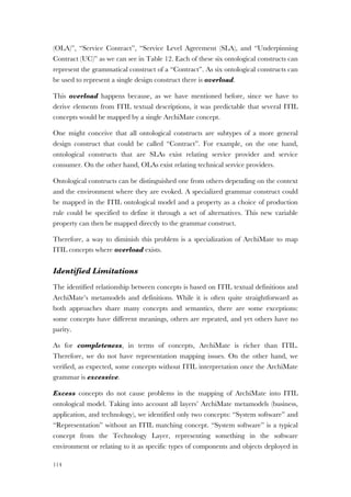
2.5.2 SOA, EA and ITIL Relationship
Braun and Winter (Braun & Winter, 2007) proposed an EA expansion to integrate
ITIL (V2 at the moment) and SOA, considering EA a pivotal concept with ITIL
regarded for IT operations.
In this paper, EA is the model to integrate the relationships among the business,
processes, application, software and technology architectures. EA provides an
overview of the IT architecture to support IT services, whereas ITIL is assigned to the
IT architecture as an essential part of management processes to services delivery.
The effective service delivery and the key elements identified in ITIL benefit from the
defined relationship between dimensions, documented in an EA framework, enabling
cross-layered analyses (Braun & Winter, 2007).
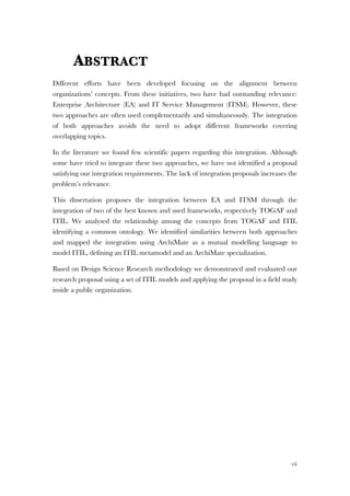
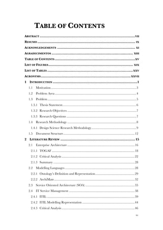
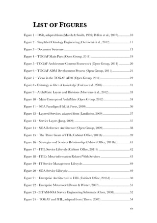
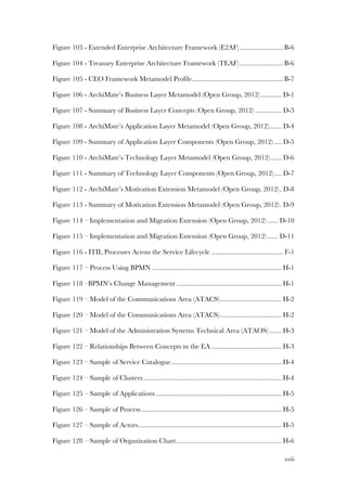
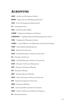
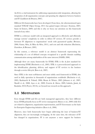
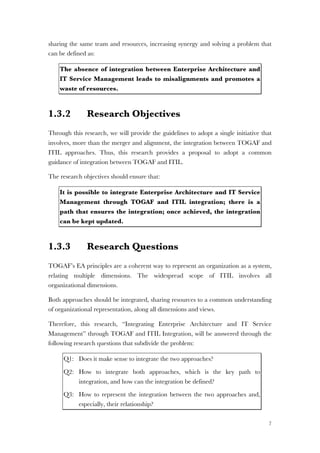
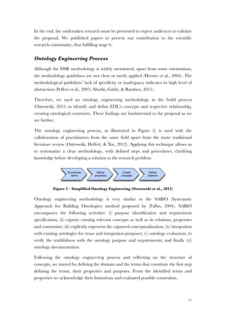
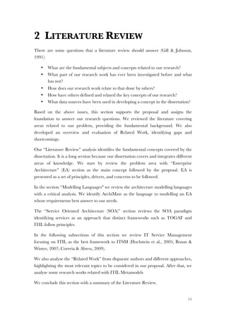
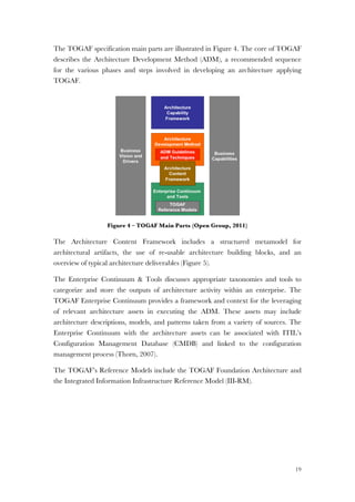
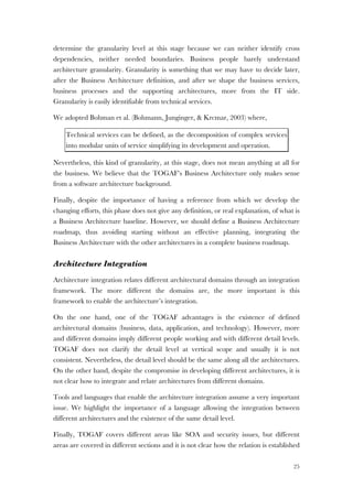
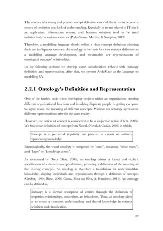
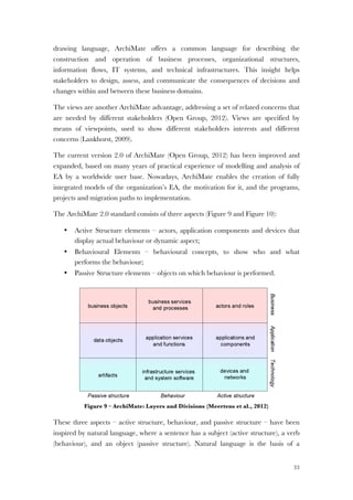
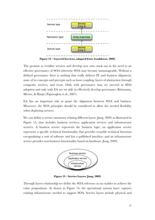
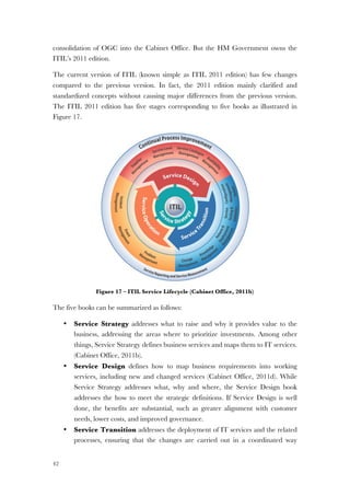
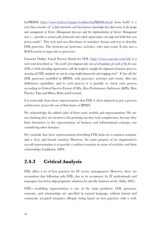
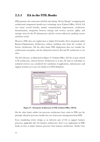
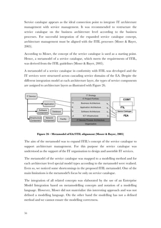
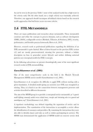
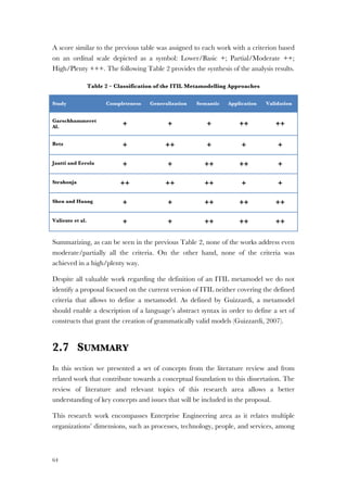
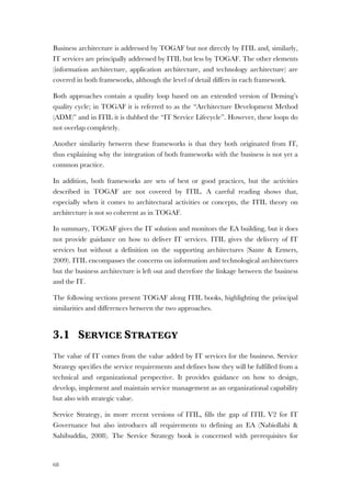
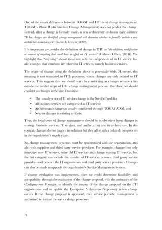
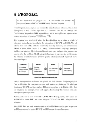
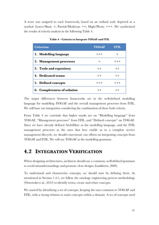
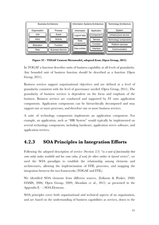
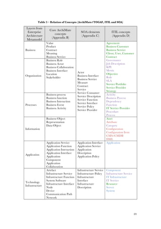
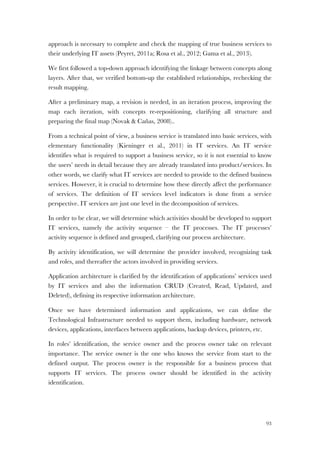
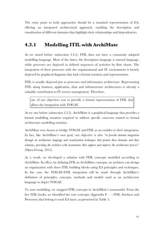
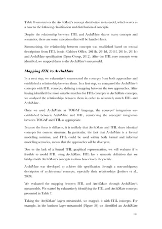
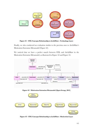
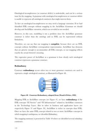
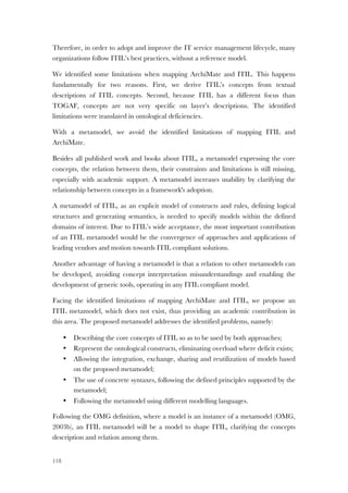
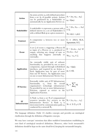
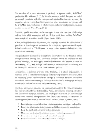
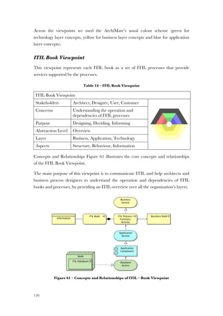
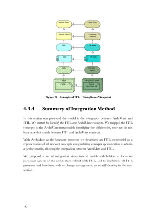
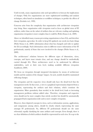
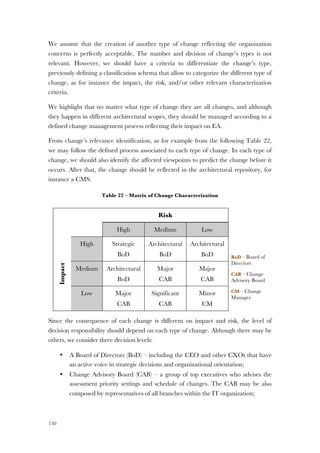
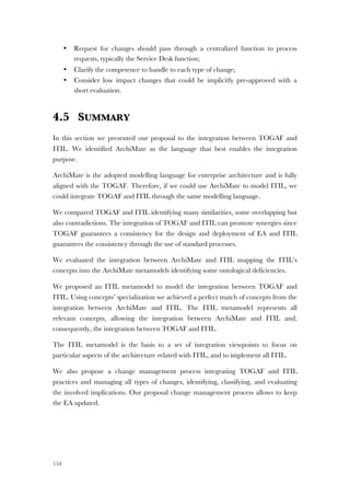
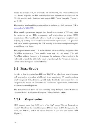
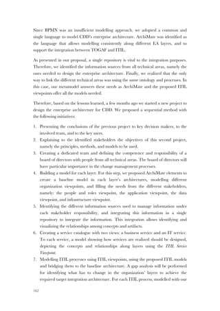
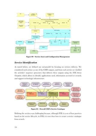
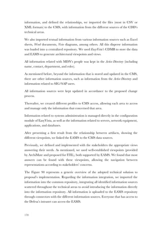
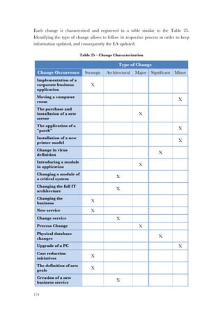
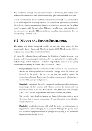
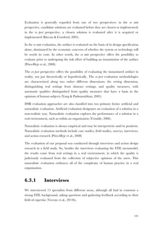
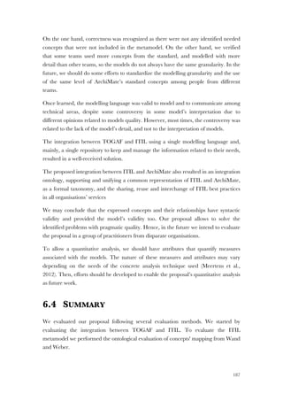
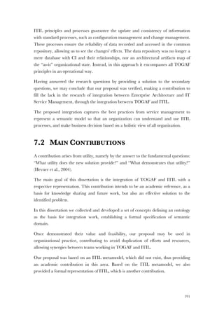
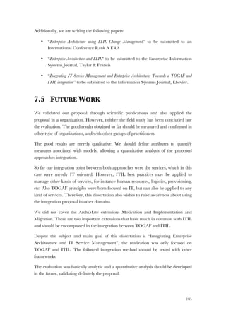
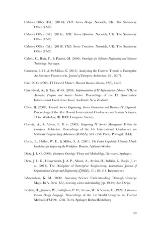
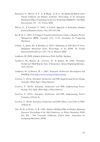
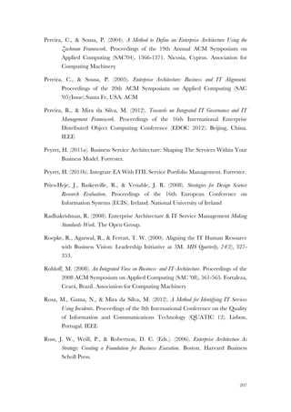
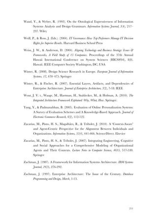
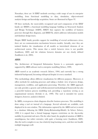
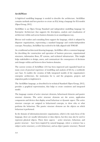
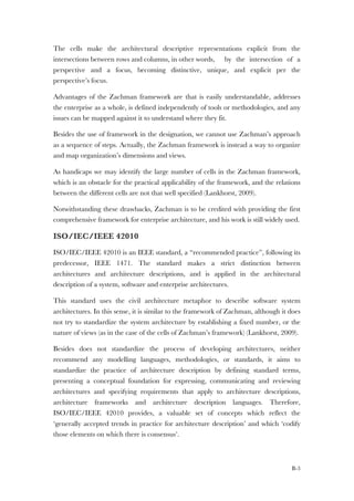
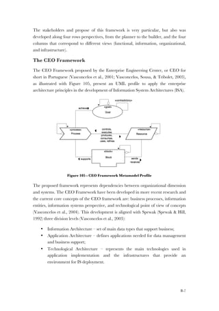
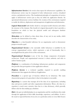
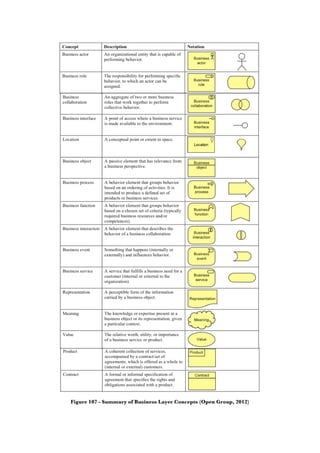
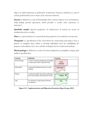
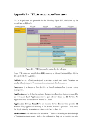
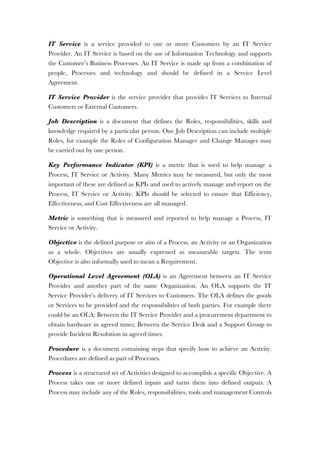
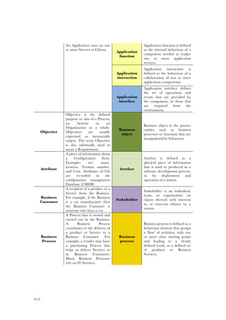
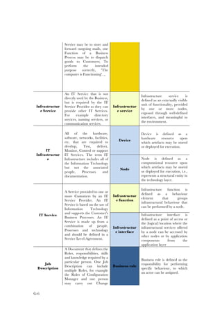
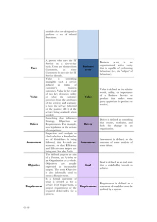
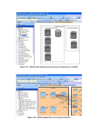
The paper proposes an enterprise metamodel (Figure 22) used to define IT services,
mapping each CMDB’s CI category into a generic framework.
Figure 22 – Enterprise Metamodel (Braun & Winter, 2007)
However, this proposal does not address the mapping between all elements, namely
the mapping between artifacts within layers, which we consider a fundamental EA
principle.
ment has to comprise the
p to IT services.
ental SOA concepts and
ture
a vision of a world in
and consistently repre-
ices [23]. Following this
of an enterprise and their
s of services. Doing that
deliver loosely coupled
ced, insourced or bundled
23].
service orientation para-
nd implementing it in an
lexibility (adaptability to
ut also agility (adaptabil-
ges) [24].
derstanding of the SOA
oftware engineering. The
m of distributed systems
mponents which can be
ns can be published and
e used more flexibly, and
Figure 3. Enterprise service metamodel
Service specification comprises all information about the service
that service users need - without having to know any implementa-
tion details of such service [25]. All available services and their
specifications are stored in a service registry. The service specifi-
cation is implemented by means of a service interface [28].
Enterprise services can be part of IT services, if they are provided
together with other service components, like infrastructure ele-
ments or additional services, like training or customizing services
(see also Fehler! Verweisquelle konnte nicht gefunden wer-
den.). Loosely coupled, reusable and composable enterprise ser-](https://image.slidesharecdn.com/79aacb86-a093-4053-9c93-f4c52ac3e033-160803192221/85/Thesis-Nelson-Gama-Integrating-EA-and-ITSM-79-320.jpg)
![54
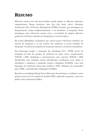
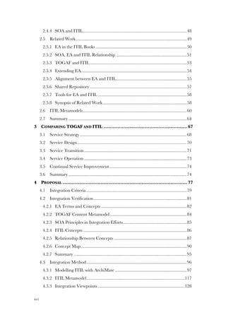
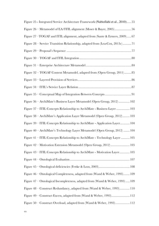
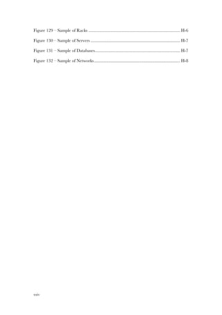
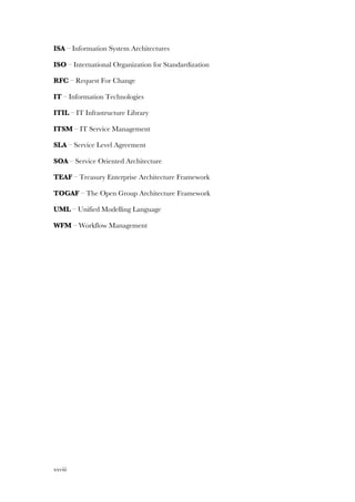
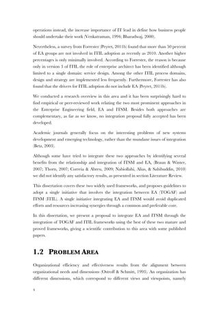
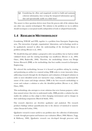
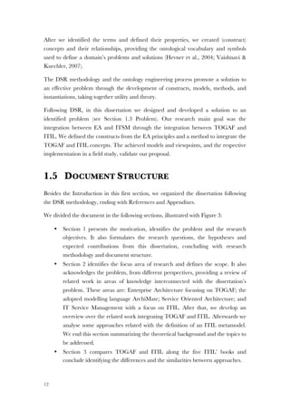
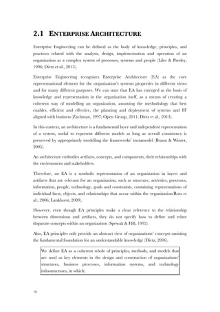
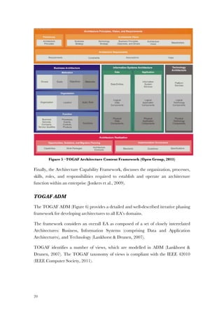
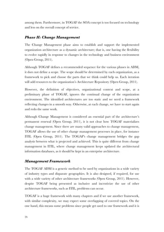
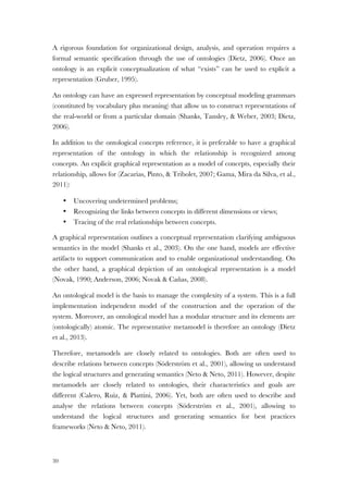
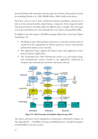
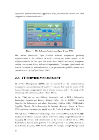
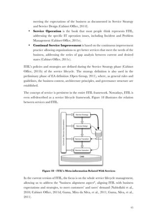
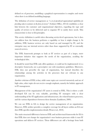
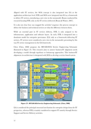
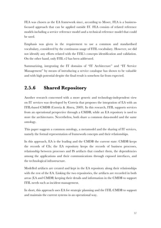
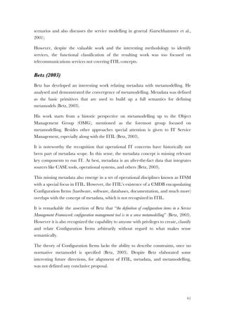
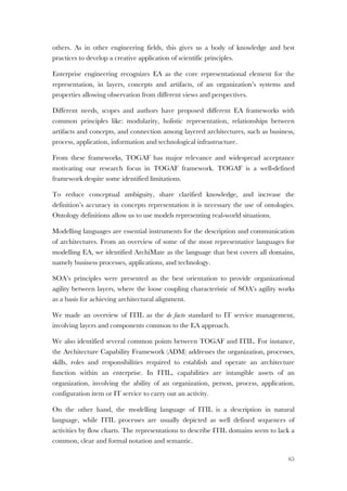
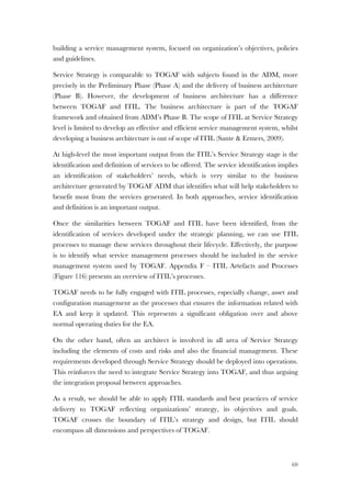
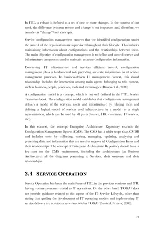
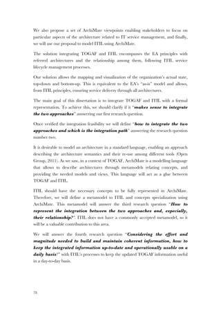
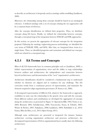
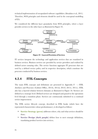
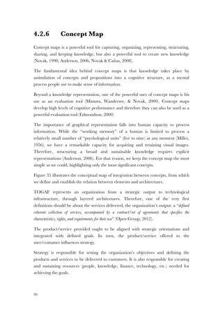
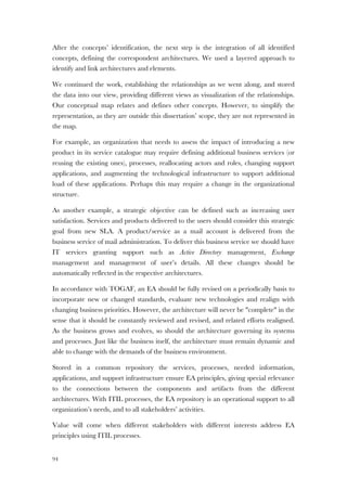
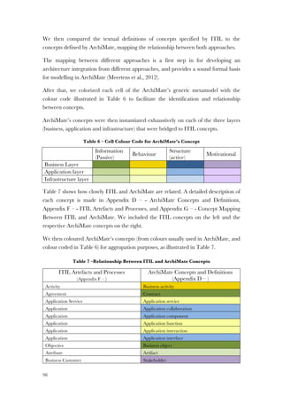
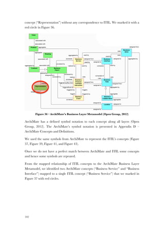
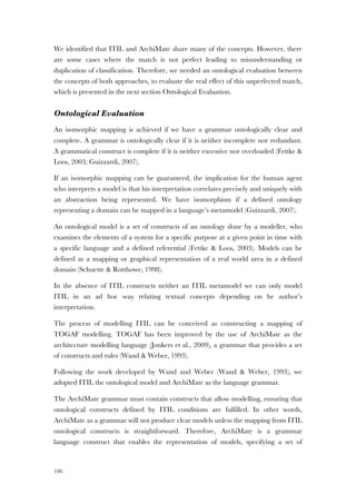
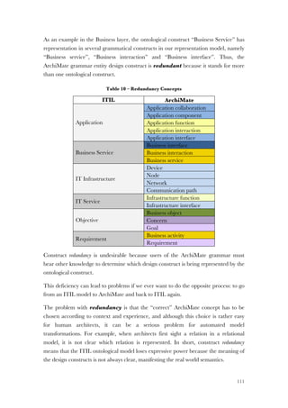
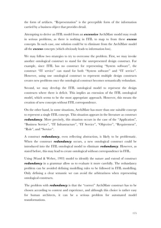
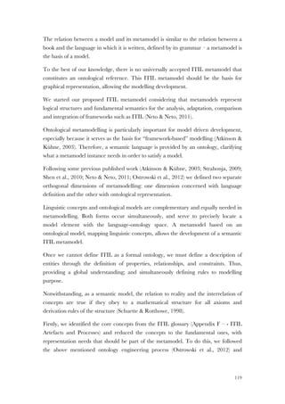
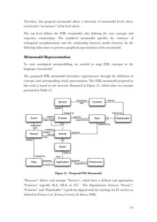
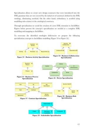
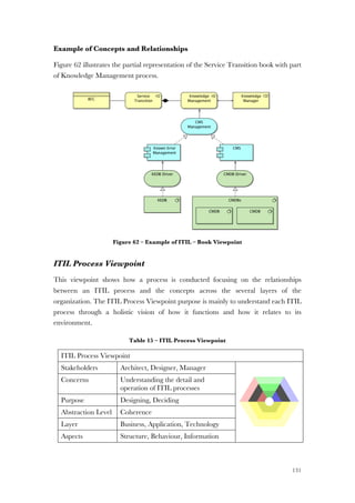
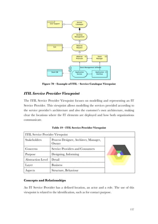
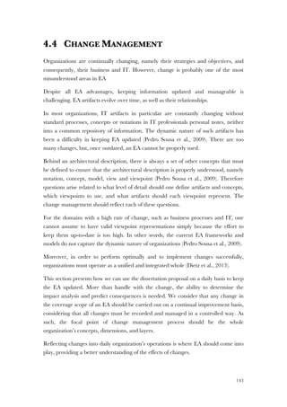
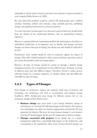
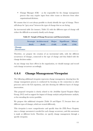
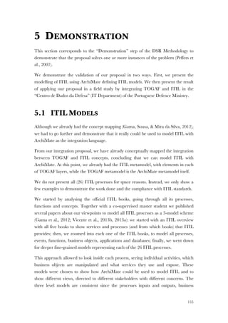
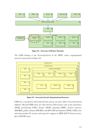
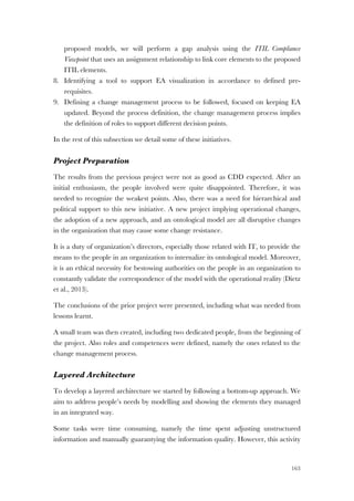
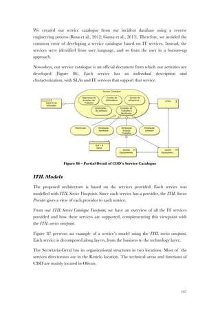
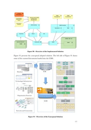
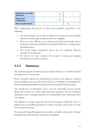
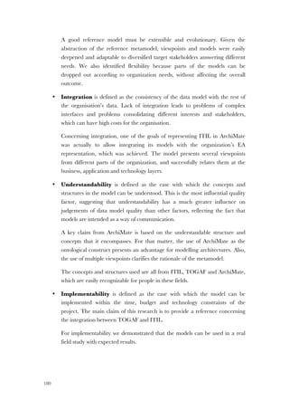
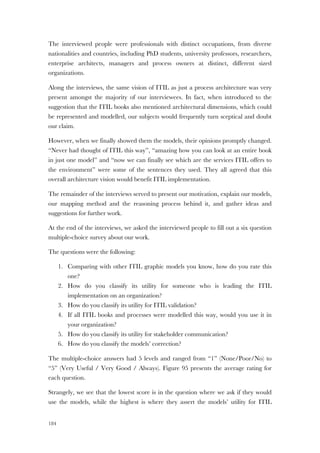
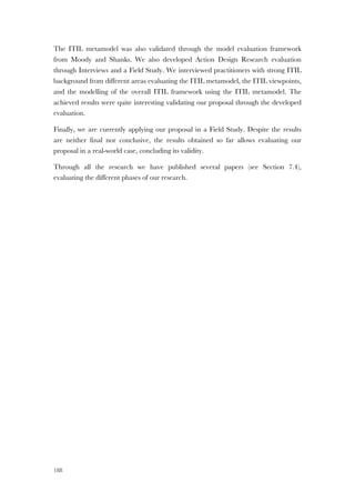
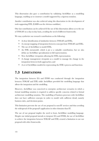
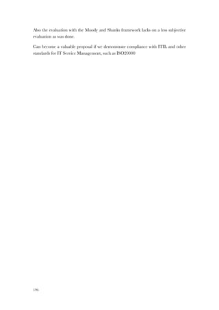
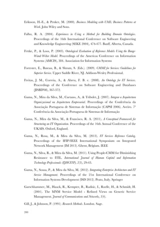
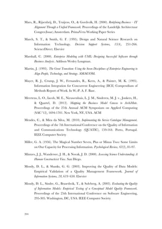
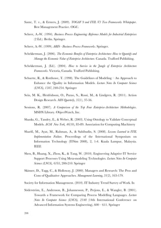
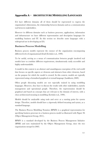
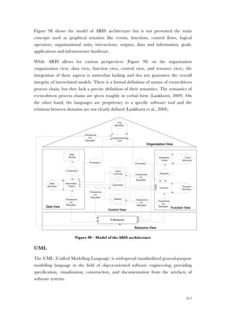
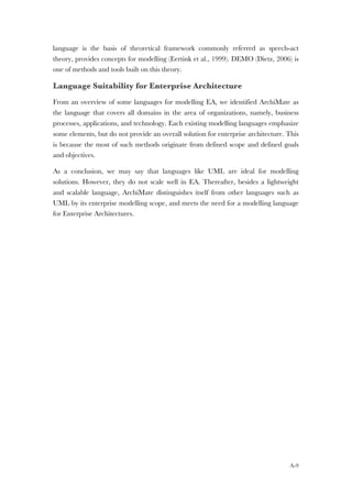
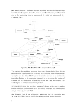
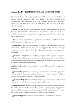
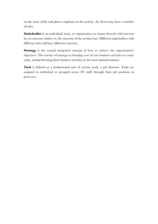
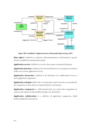
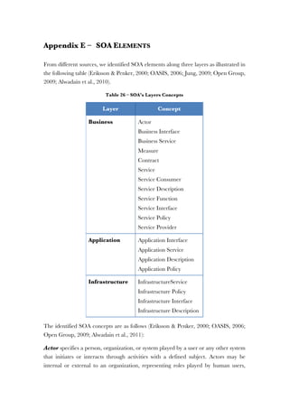
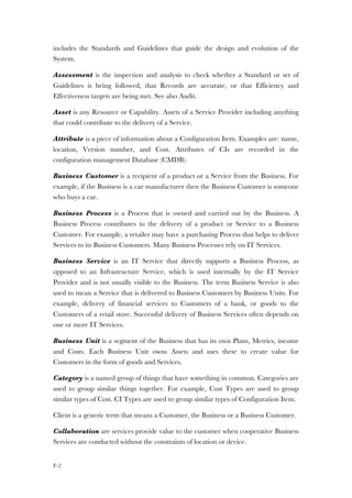
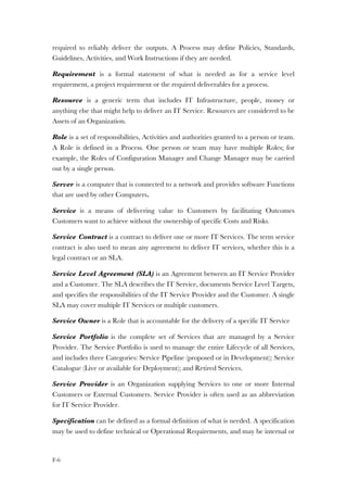
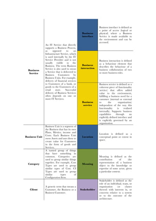
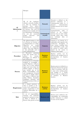
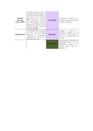
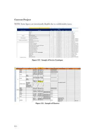
Figure 24 – TOGAF and ITIL, adapted from (Thorn, 2007)
Thorn recognized that is still needed different teams as well as different tools to
support both TOGAF and ITIL. The two frameworks are treated complementary,
since TOGAF needs an EA repository, while ITIL requires a CMDB, and alignment
between them depends on the alignment of the two metamodels. However, despite the
absence of an ITIL metamodel the authors did not proposed one.
2.5.4 Extending EA
A more recent research proposes a service based framework for EA meeting the
ITSM requirements from ITIL V3 (Nabiollahi et al., 2010). Nabiollahi et al. suggested
that EA should be extended to involve the service architecture layer from ITIL
Service Design (Cabinet Office, 2011d).
This research is one of the few studies focused on a more recent version of ITIL (ITIL
V3) proposing to cover the overall IT service management. The proposal includes an
Integrated Service Architecture Framework (ISAF) architecture model for IT services
Services
Consistence
www.via-nova-architectura.org March 2007 3
Enterprise
Continuum
Resource
Base
Figure 1. TOGAF [The Open Group, 2006].
TOGAF Architecture Development Method
Central to the discussion in this paper is TOGAF’s Architecture Development Method (ADM).
The framework considers an overall Enterprise Architecture as composed of a set of closely in-
terrelated Architectures: Business Architecture, Information Systems Architecture (comprising
Data Architecture and Application Architecture), and Technology (IT) Architecture. ADM is con-
sidered to be the core of TOGAF, and consists of a stepwise cyclic iterative approach for the
development of the overall enterprise architecture (Figure 2).
Figure 2. TOGAF ADM development process [The Open Group, 2006].
Requirements
Requirements
Solution
Solution
Service
Service
Enterprise Architecture Repository
ARCHITECTURE DEVELOPMENT AND SOLUTIONS
TOGAF
Enterprise Architecture Consistence
Problem
Incident
Configuration
Capacity
Continuity
Availability
Change
Release
SLM
Finance
CMDB
SERVICE DELIVERY
ITIL
Models](https://image.slidesharecdn.com/79aacb86-a093-4053-9c93-f4c52ac3e033-160803192221/85/Thesis-Nelson-Gama-Integrating-EA-and-ITSM-82-320.jpg)


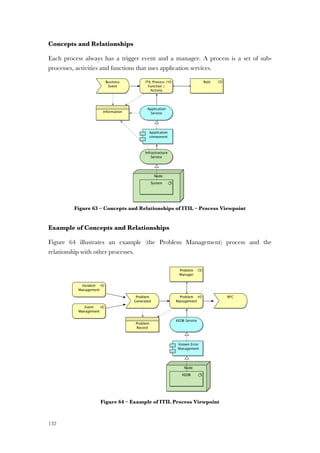
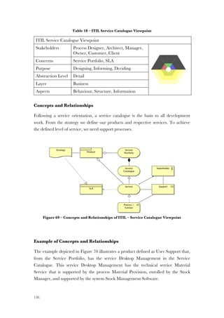


The document describes Nelson Fernando Pinheiro da Gama's thesis for obtaining a PhD in Information Systems and Computer Engineering from the University of Lisbon. The thesis proposes integrating enterprise architecture and IT service management approaches by integrating the TOGAF and ITIL frameworks. It analyzes the relationship between concepts in TOGAF and ITIL to identify common concepts. The integration is demonstrated by modeling ITIL concepts using the ArchiMate modeling language.


