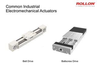
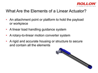
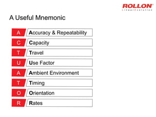
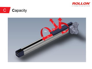
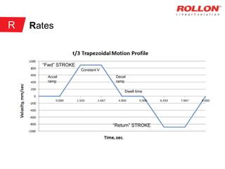
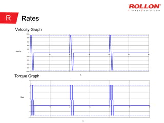
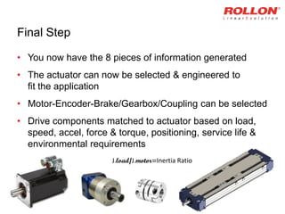
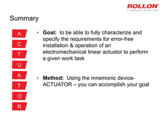
When you move, we move.
How to Specify & Size
Electromechanical Linear Actuators
Presented at IMTS 2014
Motion, Drive and Automation Conference
By Robert E. Ward, Jr.
“About half of all of our projects involving
linear actuators have a problem of some
sort – major to minor – with an actuator
before it ships out the door”
- CEO & President of a Large Systems Integrator, 2013
Common Types of Linear Actuators
Hydraulic Pneumatic Electromechanical
Common Industrial
Electromechanical Actuators
Belt Drive Ballscrew Drive
What Are the Elements of a Linear Actuator?
• An attachment point or platform to hold the payload
or workpiece
• A linear load handling guidance system
• A rotary-to-linear motion converter system
• A rigid and accurate housing or structure to secure
and contain all the elements
Specification
• Your project demands an electromechanical
linear actuator
– But how do you specify what you need?
– Where do you begin?
The Minimum Requirements
• There are just 7 Technical pieces of information to know
and understand in order to completely characterize a
linear motion electromechanical actuator for service
• And 1 Commercial piece of information that can be
equally vital to implementation of a successful linear
actuator installation
A Useful Mnemonic
Accuracy & RepeatabilityA
CapacityC
TravelT
Use FactorU
Ambient EnvironmentA
TimingT
OrientationO
RatesR
Accuracy & Repeatability
• Accuracy:
– There are 2 components
• Travel accuracy
• Positioning accuracy
– Its common to specify in units of microns (μm) or thousandths
of an inch (0.001 in.)
• Repeatability (or Precision):
– This also has 2 components
• Unidirectional
• Bi-directional
– Specify in same units as Accuracy
A
Accuracy & Repeatability
Accurate-
Not Repeatable
Repeatable-
Not Accurate
Accurate &
Repeatable
Not Accurate-
Not Repeatable
1 2
3 4
A
Capacity
• There are several types to think about when specifying
– Static Capacity, C.o (Fy,Fz)
– Dynamic Capacity, C (Fy, Fz)
– Moment Capacity, (Mx, My, Mz)
– Thrust Capacity, (Fx)
– Units of force & moment kg, N, lb
& N-m, ft-lbf, in-lbf
– 6 DoF, good actuator constrains 5
C
Capacity
Mx
Fz
Mz
C
Travel
• Also known as “stroke” in mm or inch units
• Specifying the TOTAL distance you want to move is a
critical value
• The TOTAL move needs to include “safety stroke”
(“stop-to-stop” distance)
• ROT widely used = 2x motor rev at each end
• Be careful to distinguish between Stroke and Overall
Length
T
Travel
Travel = Stroke
4x Motor Rev
Safety Stroke
Overall Length (OAL)
T
Usage Factor & Useful Life
• This spec defines how frequently you need your actuator
to run & how long you would like it to live
• Usage factor also known as Duty Cycle (On Time/Total
Time)
• Expressed in cycles/minute (cpm) is common
• An actuator cycle = 2x the Stroke
• Useful life is number of hours, years, cycles or linear
distance you desire or require the linear unit to last
U
Ambient Environment
• For best results you need to think about what
environment that the actuator will live in
– Operating Temperature range
– Relative Humidity range
– Type and amount of contaminant particles
– Presence of corrosive fluids or chemicals
– Periodic cleaning or washdown requirements
A
Timing
• This is the commercial item that you need to consider
– Project Time: What is the timing of the project
milestones? Budget approval? Engineering?
Procurement? Assembly? Check out?
– Installation Time: When do need to be up and running?
– Engineering Time: How much time is needed for
actuator integration? Are there special or custom features
that you need the actuator to have?
– Test Time: Do you need a test & development prototype
first?
T
Orientation
• This parameter tells your vendor how the linear actuator
is oriented in 3-D space
– Horizontal, table mount, 0 degrees
– Horizontal, wall mount (aka transverse)
– Horizontal, ceiling mount (aka upside down)
– Vertical, upright, 90 degrees
– Angular, variable slant angle between 0 and 90.
O
Orientation
Actuator Positions
O
Rates
• These values define the motion profile of the actuator
carriage that is carrying your workpiece
• There are 2 key values to specify or know:
– The Rate of Velocity or Speed (mm/sec, in/sec)
– The Rate of Acceleration, m/sec^2, in/sec^2
• If you know how far you want to move (stroke or travel)
and how much time to accomplish that move, then the
velocity and acceleration can be easily calculated
R
Rates
Accel
ramp
Constant V
Decel
ramp
Dwell time
“Fwd” STROKE
“Return” STROKE
R
Rates
Velocity Graph
Torque Graph
R
Final Step
• You now have the 8 pieces of information generated
• The actuator can now be selected & engineered to
fit the application
• Motor-Encoder-Brake/Gearbox/Coupling can be selected
• Drive components matched to actuator based on load,
speed, accel, force & torque, positioning, service life &
environmental requirements
J.load/J.motor=Inertia Ratio
Summary
• Goal: to be able to fully characterize and
specify the requirements for error-free
installation & operation of an
electromechanical linear actuator to perform
a given work task
• Method: Using the mnemonic device-
ACTUATOR – you can accomplish your goal
A
C
T
U
A
T
O
R

Specifying & Sizing Electromechanical Linear Actuators

  • 1.
    When you move,we move. How to Specify & Size Electromechanical Linear Actuators Presented at IMTS 2014 Motion, Drive and Automation Conference By Robert E. Ward, Jr.
  • 2.
    “About half ofall of our projects involving linear actuators have a problem of some sort – major to minor – with an actuator before it ships out the door” - CEO & President of a Large Systems Integrator, 2013
  • 3.
    Common Types ofLinear Actuators Hydraulic Pneumatic Electromechanical
  • 4.
  • 5.
    What Are theElements of a Linear Actuator? • An attachment point or platform to hold the payload or workpiece • A linear load handling guidance system • A rotary-to-linear motion converter system • A rigid and accurate housing or structure to secure and contain all the elements
  • 6.
    Specification • Your projectdemands an electromechanical linear actuator – But how do you specify what you need? – Where do you begin?
  • 7.
    The Minimum Requirements •There are just 7 Technical pieces of information to know and understand in order to completely characterize a linear motion electromechanical actuator for service • And 1 Commercial piece of information that can be equally vital to implementation of a successful linear actuator installation
  • 8.
    A Useful Mnemonic Accuracy& RepeatabilityA CapacityC TravelT Use FactorU Ambient EnvironmentA TimingT OrientationO RatesR
  • 9.
    Accuracy & Repeatability •Accuracy: – There are 2 components • Travel accuracy • Positioning accuracy – Its common to specify in units of microns (μm) or thousandths of an inch (0.001 in.) • Repeatability (or Precision): – This also has 2 components • Unidirectional • Bi-directional – Specify in same units as Accuracy A
  • 10.
    Accuracy & Repeatability Accurate- NotRepeatable Repeatable- Not Accurate Accurate & Repeatable Not Accurate- Not Repeatable 1 2 3 4 A
  • 11.
    Capacity • There areseveral types to think about when specifying – Static Capacity, C.o (Fy,Fz) – Dynamic Capacity, C (Fy, Fz) – Moment Capacity, (Mx, My, Mz) – Thrust Capacity, (Fx) – Units of force & moment kg, N, lb & N-m, ft-lbf, in-lbf – 6 DoF, good actuator constrains 5 C
  • 12.
  • 13.
    Travel • Also knownas “stroke” in mm or inch units • Specifying the TOTAL distance you want to move is a critical value • The TOTAL move needs to include “safety stroke” (“stop-to-stop” distance) • ROT widely used = 2x motor rev at each end • Be careful to distinguish between Stroke and Overall Length T
  • 14.
    Travel Travel = Stroke 4xMotor Rev Safety Stroke Overall Length (OAL) T
  • 15.
    Usage Factor &Useful Life • This spec defines how frequently you need your actuator to run & how long you would like it to live • Usage factor also known as Duty Cycle (On Time/Total Time) • Expressed in cycles/minute (cpm) is common • An actuator cycle = 2x the Stroke • Useful life is number of hours, years, cycles or linear distance you desire or require the linear unit to last U
  • 16.
    Ambient Environment • Forbest results you need to think about what environment that the actuator will live in – Operating Temperature range – Relative Humidity range – Type and amount of contaminant particles – Presence of corrosive fluids or chemicals – Periodic cleaning or washdown requirements A
  • 17.
    Timing • This isthe commercial item that you need to consider – Project Time: What is the timing of the project milestones? Budget approval? Engineering? Procurement? Assembly? Check out? – Installation Time: When do need to be up and running? – Engineering Time: How much time is needed for actuator integration? Are there special or custom features that you need the actuator to have? – Test Time: Do you need a test & development prototype first? T
  • 18.
    Orientation • This parametertells your vendor how the linear actuator is oriented in 3-D space – Horizontal, table mount, 0 degrees – Horizontal, wall mount (aka transverse) – Horizontal, ceiling mount (aka upside down) – Vertical, upright, 90 degrees – Angular, variable slant angle between 0 and 90. O
  • 19.
  • 20.
    Rates • These valuesdefine the motion profile of the actuator carriage that is carrying your workpiece • There are 2 key values to specify or know: – The Rate of Velocity or Speed (mm/sec, in/sec) – The Rate of Acceleration, m/sec^2, in/sec^2 • If you know how far you want to move (stroke or travel) and how much time to accomplish that move, then the velocity and acceleration can be easily calculated R
  • 21.
  • 22.
  • 23.
    Final Step • Younow have the 8 pieces of information generated • The actuator can now be selected & engineered to fit the application • Motor-Encoder-Brake/Gearbox/Coupling can be selected • Drive components matched to actuator based on load, speed, accel, force & torque, positioning, service life & environmental requirements J.load/J.motor=Inertia Ratio
  • 24.
    Summary • Goal: tobe able to fully characterize and specify the requirements for error-free installation & operation of an electromechanical linear actuator to perform a given work task • Method: Using the mnemonic device- ACTUATOR – you can accomplish your goal A C T U A T O R