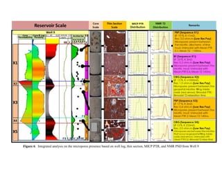
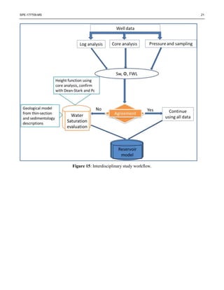
SPE-177709-MS
Evaluation of Water Saturation in a Low-Resistivity Pay Carbonate
Reservoir Onshore Abu Dhabi: An Integrated Approach
Miho Uchida, Andi Ahmad Salahuddin, Ayham Ashqar , Adedapo Noah Awolayo, Saheed Olawale Olayiwola, Abu
Dhabi Company for Onshore Petroleum Operations Ltd. (ADCO), Khaled Eissa Al Hammadi,Abu Dhabi National
Oil Company(ADNOC), Abu Dhabi, UAE
Copyright 2015, Society of Petroleum Engineers
This paper was prepared for presentation at the Abu Dhabi International Petroleum Exhibition and Conference held in Abu Dhabi, UAE, 9–12 November 2015.
This paper was selected for presentation by an SPE program committee following review of information contained in an abstract submitted by the author(s). Contents
of the paper have not been reviewed by the Society of Petroleum Engineers and are subject to correction by the author(s). The material does not necessarily reflect any
position of the Society of Petroleum Engineers, its officers, or members. Electronic reproduction, distribution, or storage of any part of this paper without the written
consent of the Society of Petroleum Engineers is prohibited. Permission to reproduce in print is restricted to an abstract of not more than 300 words; illustrations may
not be copied. The abstract must contain conspicuous acknowledgment of SPE copyright.
Abstract
Characterization and fluid quantification of Carbonate reservoirs looks more challenging than those of
sandstone reservoirs. The determination of accurate hydrocarbon saturation is more tasking due to their
complex and heterogeneous pore structures, and mineralogy. Traditionally, resistivity logs are used to
identify pay intervals due to the resistivity contrast between oil and water. However, when pay intervals
exhibit low resistivity, such logs exhibit low confidence in the precise determination of the hydrocarbon
saturation. Few Middle-Eastern reservoirs are categorized as low resistivity pay, where resistivity based
log analysis results in high water saturation. However, downhole fluid analysis identifies mobile oil, and
the formation flows dry or nearly dry oil during production tests. This makes resistivity based saturation
computation questionable.
Because of the complexity of low resistivity pay (LRP), its cause should be determined prior to applying
a solution. Several reasons were identified to be responsible for this phenomenon- among which are the
presence of micro-porosity, fractures, paramagnetic minerals, and deep conductive borehole mud
invasion. Integration of Thin section, Nuclear magnetic resonance (NMR) and Mercury injection capillary
pressure (MICP) data from the studied formation indicated the presence of micropores network.
This paper discusses the observed variations in quantifying water saturation in LRP interval and the related
discrepancies between the resistivity and non-resistivity based techniques. The non-resistivity based
methods, used in the course of this study, are coined from sigma log measurement and core data, either
capillary pressure-based (MICP, Centrifuge, and Porous plate), or direct from Dean-Stark measurements.
The interpretation process considered water saturation derived from resistivity measurement and core data
combined with production test information.
The combination of several water saturation determination approaches captured the uncertainty and
improved our understanding of the reservoir properties. This enhanced our capability to develop a robust
and reliable saturation model. The integration of data from these various sources added confidence to the
estimation of water saturation in the studied field and thus, improved reserves estimation and reservoir
simulation for accurate history matching, production forecasting and optimized field development plan.
2 SPE-177709-MS
Introduction
The studied Field is located onshore Abu Dhabi and formed as a faulted low relief four-way anticline
closure and oil bearing, separated by a major NW-SE trending fault into two areas namely Area A and
Area B (Figure 1). The studied Reservoir is part of the Lekhwair Formation belonging to Thamama Group
which was deposited during Lower Cretaceous epoch. The reservoir is highly heterogeneous with
moderate to good porosity as high as 23% while the permeability ranges from 0.02 mD to more than 1 D
(Salahuddin et al., 2015). The low pay reservoir was noted in late 1990 when a well produced oil with
zero percent water-cut, though logs interpretation indicated high water saturation, formation pressures
taken across this interval showed an oil gradient and strong shows was seen from mud logs.
Low Resistivity Pay (LRP) interval has been described as hydrocarbon bearing zone that appeared as
water interval based on open-hole resistivity measurements. Meanwhile, mud logs showed strong
hydrocarbon and such intervals produced hydrocarbon as either gas or oil with little or no water cut from
core studies, pressure and production tests (Pittman, 1971; Keith and Pittman, 1983; Worthington, 2000).
Besides, the LRP intervals were reported to be a transition zone phenomenon (Griffiths et al., 2006; Obeidi
et al., 2010). LRP zones are characterized by formation interval, with moderate to high porosities, showing
extremely low resistivity that are often less than 3 ohm-m and most frequently encountered in areas with
saline formation water.
Low pay occurs in both clastics and carbonates; while in carbonates, it has been reported to be as a result
of deep high saline mud invasion, presence of conductive minerals such as pyrite, presence of micro
porosity whose space was occupied by capillary-bound water, or anisotropic affect due to drilling high
angle wells within thin reservoirs (Griffiths, R., et al. 2006; Obeidi et al 2010; Chu and Steckhan, 2011).
Likewise, tight carbonates are often affected by deep invasion of conductive mud filtrate, which
consecutively affects deep resistivity reading (Souvick, 2003). As a result of the identified variant causes,
it is necessary to determine the main cause of LRP so as to capture the uncertainty range and arrive at the
best technique to evaluate the reservoir properties.
Fluid saturation can be determined by two different approaches; direct and indirect. The direct approach
involves direct saturation measurement in the lab using preserved core plug samples. The indirect method
is of two categories:
 the use of capillary pressure-based saturation methods on core plug samples from which the fluid
saturation are determined and
 saturation based on deep resistivity logging data using Archie module (Dandekar, 2013) or through
the use of pulsed neutron capture (PNC) surveys.
In the LRP case, utilizing Archie’s method would lead to significant overestimation of water saturation
and consequently bypassing of potential commercial reserves.
Despite the vast amount of research done in the past two decades to address this phenomenon, this issue
still persists and no unique technique has been established, particularly in carbonate reservoirs. The
discrepancy between saturation obtained from Archie’s method and well test results allows the integration
of a new evaluation approach. Hence, this paper investigates this phenomenon and lays out the best
practice workflow to define hydrocarbon saturation through an interdisciplinary study which integrates
conventional logs, core analysis (porosity, permeability, Dean-Stark, MICP, Porous Plate, and
Centrifuge), wireline formation tester (WFT), and Drill stem test (DST) results.
The advantage of using such integrated approach minimizes the error as a result of overestimating water
saturation, improves decision in well completion, improves the well performance prediction, and reduces
uncertainty in reserve estimation. Saturation profiles derived by this approach can be fitted better due to
SPE-177709-MS 3
substantial reduction in uncertainties of resistivity-based saturation data. Consequently the initialization
of in-place volumes for hydrocarbons would be properly evaluated.
Characteristics, Depositional, and Diagenetic Controls on LRP presence
A number of wells were cored and facies description was obtained. The reservoir was divided into 5 (five)
fifth-order High Resolution Sequence Stratigraphic (HRSS) sets namely as X1, X2, X3, X4, and X5
(Rebelle, 2006). The HRSS sets comprised three Highstand System Tracks (HST) separated by two
Transgressive System Tracts (TST). Core facies description indicated that the reservoir consisted of three
lithofacies based on modified Dunham’s classification (1962) namely:
 PBP (Peloidal Burrowed Packstone): Brownish Wackestone-Packstone with abundant Peloids.
 BF (Bacinella Floatstone): Floatstone with Bacinella, associated with Bivalves, Rudists and
Echinoids.
 OBG (Ooid Bacinella Grainstone): Ooids with Bacinella, Peloids, Foraminiferas, Bivalves and
Echinoids.
The interpreted depositional environment ranges from inner lagoon to inner shoal as simply illustrated in
Figure 2. Previous studies showed that complex pore distribution in carbonates play a key role in
determining accurate hydrocarbon saturations. Pittman (1971) and Keith and Pittman (1983) discovered
the presence of bimodal pore systems in carbonates as a common factor contributing to LRP interval
phenomena. The distribution of bimodal pores includes- intergranular macropores (holding and producing
moveable hydrocarbons) and adjacent micropores (holding the high saline formation brines due to high
capillary pressure). Such micropores are present between the micritic materials in lime mud as well as
between the micritic materials filling inside the grains. This creates a short circuit of the measured current
that results in low resistivity reading that in turn yield a significant underestimation of true water
saturation.
Diagenesis evaluation of this studied Reservoir was approached through core description and thin sections
observations. The identified diagenetic process that took place includes micritization, cementation,
replacement (piritization), and burial compaction. However, it was obviously observed that amongst the
above mentioned recognized diagenetic process in this reservoir, micritization was the main factor
controlling the presence of LRP interval. In other words, micropores responsible for the LRP existence
had a strong relationship with the abundance of micritic allochems (see description in Figure 3).
It was therefore important to understand the geological condition that control the spatial distribution of
high micritization versus low micritization and their associated facies within the sequence stratigraphic
framework to better capture the potential LRP intervals for future modeling purposes.
Spatial Distribution of Micritic Allochems
Micrites (carbonate mud) is an abbreviation for microcrystalline calcites which consists of 1-4 μm
diameter crystals. Scholle (1978; 2003) described micritization as a process of micrite allochems
formation through:
 its association with microbial metabolism,
 as disintegration products of coarser carbonate organisms (grains or skeletals),
 reworked particles,
 altered or neoformed,
 formed by direct inorganic precipitation, or
 precipitated during the long diagenetic history that accompanied burial.
4 SPE-177709-MS
The formation of micrite allochems led to the deterioration of rock properties by filling the original
relatively larger pore space of the rock. As the amount of micrites increased, the originally larger pore
space began to partially or fully occupy and micropores were created.
Detailed thin section observations from studied reservoir (Figure 3 and Figure 6) showed that such
micropores were present between:
 the micritic allochems of lime mud
 micrites that formed as disintegration products of the pre-existing coarser carbonate grains
 neoform micrites that existed as geopetal filling in the pre-existing chamber inside ooids and
forams.
Further evaluation of various dataset including routine core analysis, facies description, thin section, and
petrophysical logs revealed that:
i. Micritization in the studied Reservoir occurred on all the identified facies. This suggested a long
diagenetic history as early as during deposition and as late as during late burial compaction.
ii. High contents of micritic allochems quite aligned with the low resistivity response. It was therefore
reasonable enough to summarize that the vertical distribution of low resistivity pay seen on well
log would lead to a better understanding of vertical variation of micritization intensity and history
over geological time.
iii. A specific facies in a particular depositional sequence contained a large amount of micrites that in
contrast had undergone less intense micritization during other depositional sequences. For
instance, PBP facies that was deposited during sequence X1 at Well-1 was micropores-rich as a
result of high contents of micritic allochems. On the other hand, PBP facies that was deposited
during sequence X3 at Well-1 showed no or trace micritic materials resulting in non-low resistivity
reading.
This interesting phenomenon could be explained using sequence stratigraphic concept, which was
merely based on the paleobathimetry relative to sea level at a particular geological depositional
time. Intense micritization occurred on facies that deposited relatively far below the low tide
position. In contrast, the relatively less intense micritization took place in the area that were close
to the low tide as the energy at this level was strong enough to avoid intense micritization process
(Figure 4). This suggests that PBP facies in sequence X1 was deposited in the deeper part of inner
lagoon. Contrarily, PBP facies in sequence X3 was deposited in the shallow part of inner lagoon.
Other example is OBG facies in sequence X3 at Well-1 which was deposited in the deeper part of
shoal while OBG facies in sequence X4 at Well-4 was deposited in the shallower part of shoal
close to the low tide (Figure 4 and Figure 5).
iv. Aerial distribution of the LRP intervals (Figure 5) showed lateral changes which suggested that
the micritization process that took place in this reservoir might occur with different intensities over
geological time. For instance, PBP facies in the upper part of sequence X1 at Well-8 has a
relatively higher resistivity response compared to the other wells. Likewise for OBG facies in
sequence X4 at Well-8 with true resistivity reading of around 10 ohm-m, suggested that it was
deposited in the shallower part of inner shoal close to the low tide level. This observation aligned
with sequence stratigraphic concept where there is a strong connection between paleobathimetry
and micrites allochems abundance at a particular depositional time. Further analysis on the LRP
spatial variation in the future would be beneficial for predicting relative water depth, depositional
environment, and facies distribution in three dimensional earth model.
Petrophysical and Dynamic Interpretation
Wells in area A and B encountered 5 distinct pay subzones, few of which are shown in Figure 5. The
wells were drilled with water-based muds (WBM) and logged with triple combo (bulk density, neutron
SPE-177709-MS 5
porosity, and resistivity) tools as part of the open-hole (OH) logging program. The petrophysical
interpretation was carried out using these conventional logs. Porosity was interpreted from neutron density
cross plot, while the fluid saturation was computed through Archie’s method.
Water saturation was obtained via Dean-Stark analysis from cores acquired across the reservoir interval,
which was drilled using water base mud with Deuterium oxide tracer. The tracer was used as a necessary
correction measure to determine the accurate water saturation. Routine core analysis, MICP and NMR
were acquired on these cores and used to characterize the reservoir properties.
The comparison between resistivity computed saturation and core measured saturation confirmed that the
resistivity-based saturation undermined reservoir potential. Meanwhile, a close match was seen between
the porosity computed from the log and core (Figure 6). The interpreted high water log saturation was
due to either the conductive phase invasion or the presence of conductive bound water, which masked the
true formation resistivity. The average to low measured resistivity was dominated by the conductive phase,
whether these are dispersed or laminated. In case of laminated micritic distribution (Figure 7), and as a
result of the high resolution of the highly sensitive resistivity tool, which measures the horizontal
resistivity, they could overlook the hydrocarbon potential. While vertical resistivity is less affected in the
case of laminated micritic layers, however, it is not commonly acquired.
Thermal Neutron Capture Cross Section (Sigma log) is a measurement of captured neutron in the
formation after the emission of high energy neutron by the tool and it offers an alternative technique to
assess saturation. The measurement which is often used to monitor the response of the producing zone
depletion to the decay of thermal neutrons. It is mostly influenced by chlorine ion in the formation water
(high saline in this case), hence delivers saturation that is not based on conductivity. However, the tool
has short depth of investigation and as well influenced by mud invasion and the presence of high saline
capillary bound water (high chlorine) in micropores. Thus, the PNC log could only derive valid saturation
soon after the mud dissipates which might take years. With known formation water salinity, the water
saturation was calculated using:
𝑆 𝑤 =
(Σ 𝐿𝑂𝐺 − Σ 𝑀) − 𝜙(Σ 𝐻 − Σ 𝑀)
𝜙(Σ 𝑊 − Σ 𝐻)
1
Sigma log was acquired for Well-3 once and Well-1 twice, each taken after 2 years interval. Figures 13
and Figures 14 show water saturation comparison between resistivity-based and SIGMA. Sigma log of
X3 interval in Well-1 showed low water saturation compared to OH resistivity-based water saturation.
This Sigma was taken 2 years after the start of production and it indicated the influence of deep mud
invasion on the resistivity log.
Core Analysis
Around 15% of the wells in area A and B were cored; core analysis was carried out and MICP
measurement was conducted for most of the cored well. Petrophysical groups (PG) were identified based
on this core analysis (MICP data) - cross-plot of permeability and porosity, pore throat radius (PTR)
distribution, and capillary pressure (Figure 8). From the Figure, it can be seen that PG-7 (green color)
showed the best rock properties, they have high permeability and porosity, with dual pore system as seen
on the pore throat radius (PTR) distribution and low entry capillary pressure. While PG-1 (blue color)
showed the poorest rock properties – low permeability and porosity, with single pore system as seen on
the pore throat radius (PTR) distribution and high entry capillary pressure. NMR measurement generated
echo decay sequences as a result of the sample magnetization decay, response of which was inverted to
pore size distribution (PSD). The T2 cutoff in the case of dual pore system ranges between 120-150 ms.
which was to distinguish microporosity from macroporosity.
Figure 6 shows integrated analysis of the presence of micropores based on well log, thin section, MICP,
6 SPE-177709-MS
and NMR from Well-9. Thin section from 5 (five) different samples across the interval displayed the
presence of micropores between micritic materials as discussed earlier. This is then further supported by
MICP result which shows low PTR value of 0.01 to 1 microns that mostly exist in the poor rock quality,
while the good rock quality showed a bimodal distribution comprising low PTR and high PTR (>10
microns) but majorly dominated by the high PTR. NMR pore size distribution showed similar trend with
the MICP distribution, though the two measurements assessed the same pore space but in a different
manner. The difference is as a result of the injected mercury ‘moving’ through the pore throats as in the
MICP case and NMR ‘probing’ the pore volume. Likewise, MICP measurements are carried out on a chip
of rock sample, which assess a little portion of the rock while NMR measurements are conducted on the
whole core plug. Bound and mobile phases were clearly identified from the NMR spectrum as well as
from the MICP on the same sample with dual pore system.
Based on the MICP measurement data and FWL interpretation, saturation height model was developed
for each PG using J-function (Equation 2). The J function curves were normalized for each PG with power
equation to obtain single J function for each particular PG. The modeled saturation height functions are
shown in Figure 9.
𝐽(𝑆 𝑤) =
0.217𝑃𝑐
𝜎 cos 𝜃
√
𝑘
𝜙
2
Dean-Stark (DS) analysis was carried out on Well-7 and Well-9. Dean-Stark analysis was the only
direct saturation measurement approach used in this studied reservoir. Water saturation of the wells is
shown in Figure 6 and Figure 14 as black dots and it showed lower water saturation than resistivity-
based saturation. However, core from tight intervals could give inaccurate saturation because of the
tendency to prematurely terminate the distillation process due to low rate of water recovery, under the
assumption that the process was over (Dandekar, 2013). Similarly, there could be error in the calculation
of water saturation from the tracer correction. Hence, Dean-Stark analysis could undermine the water
saturation in this tight zone. Therefore, the discussion in this study focused on Dean-Stark analysis in
good quality rock interval.
Special core analysis was carried out on Well-9 cored in Area B. The measurements carried out include
porous plate capillary pressure and centrifuge water–oil capillary pressure. The information generated
these sources was used in establishing capillary pressure saturation modeling for the dynamic simulation
model input. The selected cores that showed similar capillary pressure trend were grouped accordingly
into the three groups. Figure 10 shows the model capillary pressure where PG_HIGH represented PG-6
– PG-7, PG_MED represented PG-3 – PG-5 while RRT_LOW represented PG-1 – PG-2.
Wireline Formation Testers and Production Tests
Given the limitations of a resistivity-based interpretation approach, the alternative is to use pressure
gradient profiles to determine the fluid contacts. Pressure points acquired across the formation interval
using Wireline formation testers were gathered from different wells. The results are in plotted in Figure
11 for Area A and Figure 12 for Area B.
In Area A, Well-1, Well-3 and Well-13 showed an average oil gradient of 0.342 psi/ft., while Well-2,
Well-4 and Well-14 showed an average gradient of 0.49 psi/ft. considering formation water salinity of
200,000ppm. Well-15 pressure points deviated from other points due to pressure depletion that occurred
overtime in the area; however an oil gradient of 0.34psi/ft. was obtained. This showed completely oil zone
in the interval between XX25 and XX50 and completely water zone below XX75. Thus, the interval
between XX50 and XX75 showed a clear indication of the transition zone, the free water level (FWL) was
better positioned by considering production tests data (Figure 11). DST from Well-1 and Well-3 at the
interval (XX25 and XX50) produced oil with 0-3% water cut. Well-1 was placed on production across
SPE-177709-MS 7
this interval and produced oil with only about 5% water cut till date. Test carried out in the interval
between XX50 and XX75 produced almost 100% water for Well-2 and Well-13. Combining the possible
cross-over of the oil and water gradient with the production tests, gave the confidence of placing the FWL
at midpoint between XX50 and XX75 with uncertainty of ±10ft.
In Area B, Well-5, Well-6 (upper pressure points) and well-10 showed an average oil gradient of 0.3 psi/ft.
which indicated that interval between XX80 and XX120 were located in the oil zone. Upper pressure
points of Well-9, which were taken after little pressure depletion, showed an oil gradient of 0.32 psi/ft.
While lower pressure points of Well-6 and Well-9 showed a water gradient of 0.49 psi/ft. Because not
many pressure points were taken below XX120, uncertainties ensued. But combining the points with test
data helped to position the FWL. Similar to what was mentioned in Area A, Well-5, Well-11 and Well-12
produced thousand barrels of oil with no water cut and supported the fact that XX80 - XX120 was located
in the oil zone. Fluid analyzer coupled with WFT in Well-9 showed water with a trace amount of oil, while
production test produced 100% water. Then the FWL was observed to lie in the interval between XX120
and XX140 and selected close to XX140 due to more uncertainty around this interval.
Data Integration
One the main task was to build a saturation model for hydrocarbon volume calculation. The resistivity-
based saturation log exhibited a water zone. Integrating several approaches to model the water saturation
was required since the problem was actually related to the structurally-parallel FWL based on log. Figure
13 and Figure 14 shows the comparison of various saturation calculation approaches which was discussed
earlier based on well correlation. Figure 13 shows the comparison between Well-2, Well-3 and Well-1 in
Area A and Figure 14 shows the comparison between Well-6, Well-7 and Well-5 in Area B.
Critical evaluation of the interval between XX25 and XX50 (which showed oil interval from WFT and
test data analysis) on electrical log showed low resistivity. The crestal wells (Well-3 and Well-1) in Area
A possessed similar rock characteristics as could be seen in Figure 13. The resistivity from X1 and X3
with very good rock properties (PG4 – PG7) was low, which indicated overestimation of the water
saturation.
Comparing saturation from Archie with the one from Sigma log taken 2 years after OH logging in Well-
1 showed mud dissipation and oil reoccupation of the vacant pores. The sigma log taken 4 years later
confirmed the movement of the oil during production. The water saturation from Sigma log indicated that
the zone of interest contained 20-25% water saturation that almost confirm with the core.
Saturation height model from MICP showed a good oil saturation which is consistent with the sigma-
based saturation. Capillary pressure-saturation (PC-Sw) relationship derived from SCAL showed a very
good consistency with the aforementioned methods. This gave the confidence that the interval between
XX25 and XX50 is an oil interval and its evaluation based on resistivity-based method was not accurate.
Below XX50 in the transition zone, above the selected FWL, the three approaches showed consistent
result aside the resistivity-based method. Another interesting note was that the resistivity-based method
in Well-2 showed average saturation of 80% below the FWL, whereas during testing 100% water was
produced. Hence, the oil observed in the resistivity-based method could represent the residual oil
saturation.
Well-5, located on the crestal part of Area B, showed low resistivity on X1 and X3 layer though the well
possessed very good rock properties (PG4 – PG7). In the above discussion, XX80 – XX120 was identified
as an oil zone which produced oil with trace or no water. The saturation from resistivity-based method
overestimated the water saturation, while saturation from SHM from MICP and PC-Sw from SCAL were
consistent. Well-7 showed good consistency between resistivity-based method, SHM, CP-Sw and Dean-
Stark around this interval. The observed FWL was also justified with the consistency between all the
approaches in the interval between XX120 and XX160.
8 SPE-177709-MS
Finally, data integration of the above showed that saturations based on Archie are prone to higher
uncertainties, if compared to those derived by the SHM, Sigma log, Dean-Stark, and PC-Sw method, in the
pay intervals, due to a relatively low resistivity measured by electrical log. Choosing one method of
saturation while disregarding the others may not be ideal, on the contrary, integration of more than one
method to identify the potential uncertainty range is highly recommended. This interdisciplinary study
was carried out using the workflow presented in Figure 15. There are significant differences in
hydrocarbon volumes calculated from the different methodologies, which can be as much as five times
the calculated volume. The probable cause of this low resistivity phenomenon which has been identified
during the course of this study is the presence of micropores and deep mud invasion.
Since all intervals producing water-free oil were identified by WFT, and further confirmed by production
tests, using overestimated water saturation from resistivity-based method in the LRP significantly
underestimated reserves. Consequently, the calculation of oil originally in place (OOIP) improved
drastically when initializing the dynamic model from enhanced FWL estimations and saturation height
equations (modeled from the capillary pressure dataset) instead of using hydrocarbon “down-to” or “up-
to” conditions for the assumed hydrocarbon column per structure and compartment. At the same time,
updated dynamic simulation model based on PG capillary pressure dataset showed good history matching;
it means updated saturation distribution is more representative than resistivity based one.
Conclusion/Recommendations
 The identified probable causes of LRP in the studied reservoir are the existing micropores and deep
mud invasion.
 The integrated study has shown the effectiveness of saturation height function (SHF) based on
petrophysical grouping (PG) from core analysis in mitigating the uncertainties of resistivity-based
saturation.
 For LRP reservoir, improving FWL accuracy is critical in the evaluation of the pay zone.
 A robust workflow has been illustrated to evaluate water saturation in LRP. This workflow could be
applied to conventional reservoirs.
 Integration of several approaches is recommended to capture the potential uncertainty in the water
saturation calculation.
 In order to better understand LRP interval the following should be addressed: multidisciplinary
integrated studies and better understand of the sedimentological and diagenetical process that control
the spatial distribution of LRP zone.
Acknowledgement
The authors would like to appreciate ADCO management and its shareholders for granting the permission
to present this paper.
Nomenclature
∑H Sigma of the Hydrocarbon
∑LOG Sigma of the Formation
∑M Sigma of the Matrix
∑W Sigma of the Water
DST Drill stem test
SPE-177709-MS 9
FWL Free water level
HRSS High Resolution Sequence Stratigraphic
HST Highstand System Tracks
k Permeability
LRP Low resistivity pay
MICP Mercury injection capillary pressure
NMR Nuclear magnetic resonance
OH open-hole
ɸ Porosity
PC Capillary pressure
PG Petrophysical groups
PNC pulsed neutron capture
PSD pore size distribution
PTR pore throat radius
SW Water Saturation
WBM Water base mud
WFT Wireline formation tester
𝜃 Angle
𝜎 Interfacial tension
References
Chu, W., and Steckhan, J. (2011). A Practical Approach to Determine Low-Resistivity Pay in Clastic
Reservoirs. Society of Petroleum Engineers. SPE ATCE. SPE-147360
Dandekar, A. Y. (2013). Petroleum reservoir rock and fluid properties. CRC press.
Dunham, R.J. (1962). Classification of Carbonate Rocks According to Depositional Texture. AAPG
Memoir 1, p 108 – 121.
Farouk A., Wibowo, S., Aillud, G., Al Shehhi, A. and Kingsley, K. (2014). Water Saturation Uncertainty
of Tight, Microporosity Dominated carbonate reservoirs and the Impact of Hydrocarbon Volume; Case
Study from Abu Dhabi, UAE. Paper presented at the SPWLA 55th Annual Logging Symposium held in
Abu Dhabi, UAE, May 18-22.
Griffiths, R., Carnegie, A., Gyllensten, A., Ribeiro, M.T., Prasodjo, A., Sallam, Y., (2006). Evaluation of
Low Resistivity Pay In Carbonates - A Breakthrough. Society of Petrophysicists and Well-Log Analysts.
Paper E presented at the SPWLA 47th Annual Logging Symposium held in Veracruz, Mexico, June 4-7.
Gyllensten, A., Radwan, E.S., Al Hammadi, M., I., Maskary, S. S., (2007) A new saturation model for
low resistivity pay in carbonates, SPWLA, PP7.
Keith, B. D., and Pittman, E. D. (1983). Bimodal porosity in oolitic reservoir - effect on productivity and
log response, Rodessa limestone (Lower Cretaceous), East Texas basin. AAPG Bulletin, v. 67, no. 9, p.
1391–1399.
Lucia, F.J. 1999. Carbonate Reservoir Characterization, 226. New York: Springer.
Obeidi, A., Al Aryani, F., and Al Amoudi, M. (2010). Developed Approach for Better Understanding of
Low Resistivity Pay Carbonate Reservoirs. Paper SPE-137663 presented at Abu Dhabi International
Conference and Exhibition. Abu Dhabi.
Pittman, E. D. 1971. Microporosity in carbonate rocks. AAPG Bulletin, v. 55, no. 10, p. 1873-1881.
Rebelle, M. and Al Nuaimi, M.A. (2006). Lithofacies, Depositional Environment, and High-Resolution
10 SPE-177709-MS
Sequence Stratigraphy interpretation of Reservoir-X, Field A. ADCO Internal Report.
Salahuddin, A.A., Gibrata M.A., Uchida. M., Al Hammadi, K.E., Binmadhi, A.K. (2015). Innovative
Integration of Subsurface Data and History Matching Validation to Characterize and Model Complex
Carbonate Reservoir with High Permeability Streaks and Low Resistivity Pay Issues, Onshore Abu Dhabi.
SPE Reservoir Characterisation and Simulation Conference and Exhibition. SPE-175682.
Scholle, P. A. (1978). A Color Illustrated Guide to Carbonate Rock Constituents, Textures, Cements, and
Porosities. AAPG Memoir 27.
Scholle, P. A., and Ulmer-Scholle, D. S. (2003). A Color Guide to the Petrography of Carbonate Rocks:
Grains, Textures, Porosity, Diagenesis, AAPG Memoir 77 (Vol. 77). AAPG.
Souvick, S. (2003). Low-resistivity pay (LRP): ideas for solution. Paper SPE-85675 presented at Nigeria
Annual International Conference and Exhibition. Society of Petroleum Engineers.
Strohmenger, C. J., Weber, L. J., Ghani, A., Rebelle, M., Al-Mehsin, K., Al-Jeelani, O., and Suwaina, O.
(2004). High-resolution sequence stratigraphy of the Kharaib Formation (Lower Cretaceous, UAE).
Paper SPE-88729 presented at Abu Dhabi International Conference and Exhibition. Abu Dhabi.
Thomas, E. C., and Stieber, S. J., (1975) Distribution of shale in sandstones and its effect upon porosity:
16th Annual Logging Symposium, SPWLA.
Worthington, P. F. (2000). Recognition and evaluation of low-resistivity pay. Petroleum Geoscience, 6(1),
p. 77-92.
SPE-177709-MS 11
Figure 1: Reservoir Top depth map and key wells location
Figure 2: Paleobathymetric profile showing the interpreted
Depositional environment and lateral facies distribution.
PBP (Peloidal Burrowed Packstone); BF (Bacinella Floatstone); OBG (Ooid Bacinella Grainstone).
Figure 3: Vertical distribution of Low Resistivity Pay intervals,
micritic allochems and micropores presence
OBG (Sequence X3):
Ø ~12%. K ~4mD. Res: <3 ohm.m
(Low Res Pay)
Micritic allochems of lime mud. Micrites
are also presence as geopetal filling in
the pre-existing chamber inside ooids
and forams ( neoform).
Well Scale Thin Setion Scale
PBP (Sequence X3):
Ø ~8%. K ~2mD. Res: >6 ohm.m
(non- Low Res Pay)
PBP (Sequence X1):
Ø ~11 %. K <1mD.
Res: <3 ohm.m (Low Res Pay)
Micropores present between the
micritic allochems of lime mud
X1
X3
X5
X2
X4
Trace or none micropores observed
BF (Sequence X3): Ø ~21%. K ~3mD.
Res: <3 ohm.m (Low Res Pay)
Micrites formed as disintegration
products of the pre-existing coarser
carbonate grains
Well 1
Archie
Sw
1 ------------------------ 0
Core
Permeability
Core & Log
Porosity
12 SPE-177709-MS
Figure 4: Geological control for the spatial distribution of micrites intensity
Figure 5: Stratigraphic cross section (flattened at Reservoir Top) showing vertical and aerial distribution
of Low Resistivity Pay interval on some key wells
Figure 6: Integrated analysis on the micropores presence based on well log, thin section, MICP PTR, and NMR PSD from Well 9
Figure 7: Vertical and horizontal resistivity of a layered system with alternating water and oil intervals (Gyllensten et al., 2007).
Figure 8: Seven identified Petrophysical Groups based on Porosity-Permeability, Pc-Sw and Pore Throat Radius-Distribution
PetrophysicalGroups from studied Field
Figure 9: Saturation Height Modeling from MICP rock-typed specific (Leveret J-function based).
Figure 10: Capillary pressure-saturation from Porous plate/Centrifuge
0
1
2
3
0 0.2 0.4 0.6 0.8 1
J-Function
Sw
Saturation Height Function
PG1
PG2
PG3
PG4
PG5
PG6
PG7
0
40
80
120
160
200
0 0.2 0.4 0.6 0.8 1
Pcpsia
Sw
CP-Sw
PG_HIGH
PG_MED
PG_LOW
Figure 11: WFT pressure points and Production test for Area A.
Figure 12: WFT pressure points and Production test for Area B
SPE-177709-MS 19
Figure 13: Structural well correlation comparing all saturation based methods in Area A.
 Track 1: Log and Core Permeability.
 Track 2: Log and core porosity.
 Track 3: Horizontal resistivity (black) is used as Rt for saturation computation in
conventional analysis.
 Track 4: Density Neutron log.
 Track 5: Open-hole saturation based on Archie compared with RST at initial time.
 Track 6: Saturation compared from initial RST with the final RST.
 Track 7: Model Saturation based on SCAL data input
 Track 8: Saturation height model based on MICP data input
 Track 9: Petrophysical group
20 SPE-177709-MS
Figure 14: Structural well correlation comparing all saturation based methods in Area B.
 Track 1: Log and Core Permeability.
 Track 2: Log and core porosity.
 Track 3: Horizontal resistivity (black) was used as Rt for saturation computation
in conventional analysis.
 Track 4: Density Neutron log.
 Track 5: Open-hole saturation based on Archie compared with saturation from
Dean-Stark (especially for well 7).
 Track 6: Model Saturation based on SCAL data input compared with saturation
from Dean-Stark (especially for well 7).
 Track 7: Saturation height model based on MICP data input compared with
saturation from Dean-Stark (especially for well 7).
 Track 8: Petrophysical group
SPE-177709-MS 21
Figure 15: Interdisciplinary study workflow.

SPE-177709 LRP_Paper

  • 1.
    SPE-177709-MS Evaluation of WaterSaturation in a Low-Resistivity Pay Carbonate Reservoir Onshore Abu Dhabi: An Integrated Approach Miho Uchida, Andi Ahmad Salahuddin, Ayham Ashqar , Adedapo Noah Awolayo, Saheed Olawale Olayiwola, Abu Dhabi Company for Onshore Petroleum Operations Ltd. (ADCO), Khaled Eissa Al Hammadi,Abu Dhabi National Oil Company(ADNOC), Abu Dhabi, UAE Copyright 2015, Society of Petroleum Engineers This paper was prepared for presentation at the Abu Dhabi International Petroleum Exhibition and Conference held in Abu Dhabi, UAE, 9–12 November 2015. This paper was selected for presentation by an SPE program committee following review of information contained in an abstract submitted by the author(s). Contents of the paper have not been reviewed by the Society of Petroleum Engineers and are subject to correction by the author(s). The material does not necessarily reflect any position of the Society of Petroleum Engineers, its officers, or members. Electronic reproduction, distribution, or storage of any part of this paper without the written consent of the Society of Petroleum Engineers is prohibited. Permission to reproduce in print is restricted to an abstract of not more than 300 words; illustrations may not be copied. The abstract must contain conspicuous acknowledgment of SPE copyright. Abstract Characterization and fluid quantification of Carbonate reservoirs looks more challenging than those of sandstone reservoirs. The determination of accurate hydrocarbon saturation is more tasking due to their complex and heterogeneous pore structures, and mineralogy. Traditionally, resistivity logs are used to identify pay intervals due to the resistivity contrast between oil and water. However, when pay intervals exhibit low resistivity, such logs exhibit low confidence in the precise determination of the hydrocarbon saturation. Few Middle-Eastern reservoirs are categorized as low resistivity pay, where resistivity based log analysis results in high water saturation. However, downhole fluid analysis identifies mobile oil, and the formation flows dry or nearly dry oil during production tests. This makes resistivity based saturation computation questionable. Because of the complexity of low resistivity pay (LRP), its cause should be determined prior to applying a solution. Several reasons were identified to be responsible for this phenomenon- among which are the presence of micro-porosity, fractures, paramagnetic minerals, and deep conductive borehole mud invasion. Integration of Thin section, Nuclear magnetic resonance (NMR) and Mercury injection capillary pressure (MICP) data from the studied formation indicated the presence of micropores network. This paper discusses the observed variations in quantifying water saturation in LRP interval and the related discrepancies between the resistivity and non-resistivity based techniques. The non-resistivity based methods, used in the course of this study, are coined from sigma log measurement and core data, either capillary pressure-based (MICP, Centrifuge, and Porous plate), or direct from Dean-Stark measurements. The interpretation process considered water saturation derived from resistivity measurement and core data combined with production test information. The combination of several water saturation determination approaches captured the uncertainty and improved our understanding of the reservoir properties. This enhanced our capability to develop a robust and reliable saturation model. The integration of data from these various sources added confidence to the estimation of water saturation in the studied field and thus, improved reserves estimation and reservoir simulation for accurate history matching, production forecasting and optimized field development plan.
  • 2.
    2 SPE-177709-MS Introduction The studiedField is located onshore Abu Dhabi and formed as a faulted low relief four-way anticline closure and oil bearing, separated by a major NW-SE trending fault into two areas namely Area A and Area B (Figure 1). The studied Reservoir is part of the Lekhwair Formation belonging to Thamama Group which was deposited during Lower Cretaceous epoch. The reservoir is highly heterogeneous with moderate to good porosity as high as 23% while the permeability ranges from 0.02 mD to more than 1 D (Salahuddin et al., 2015). The low pay reservoir was noted in late 1990 when a well produced oil with zero percent water-cut, though logs interpretation indicated high water saturation, formation pressures taken across this interval showed an oil gradient and strong shows was seen from mud logs. Low Resistivity Pay (LRP) interval has been described as hydrocarbon bearing zone that appeared as water interval based on open-hole resistivity measurements. Meanwhile, mud logs showed strong hydrocarbon and such intervals produced hydrocarbon as either gas or oil with little or no water cut from core studies, pressure and production tests (Pittman, 1971; Keith and Pittman, 1983; Worthington, 2000). Besides, the LRP intervals were reported to be a transition zone phenomenon (Griffiths et al., 2006; Obeidi et al., 2010). LRP zones are characterized by formation interval, with moderate to high porosities, showing extremely low resistivity that are often less than 3 ohm-m and most frequently encountered in areas with saline formation water. Low pay occurs in both clastics and carbonates; while in carbonates, it has been reported to be as a result of deep high saline mud invasion, presence of conductive minerals such as pyrite, presence of micro porosity whose space was occupied by capillary-bound water, or anisotropic affect due to drilling high angle wells within thin reservoirs (Griffiths, R., et al. 2006; Obeidi et al 2010; Chu and Steckhan, 2011). Likewise, tight carbonates are often affected by deep invasion of conductive mud filtrate, which consecutively affects deep resistivity reading (Souvick, 2003). As a result of the identified variant causes, it is necessary to determine the main cause of LRP so as to capture the uncertainty range and arrive at the best technique to evaluate the reservoir properties. Fluid saturation can be determined by two different approaches; direct and indirect. The direct approach involves direct saturation measurement in the lab using preserved core plug samples. The indirect method is of two categories:  the use of capillary pressure-based saturation methods on core plug samples from which the fluid saturation are determined and  saturation based on deep resistivity logging data using Archie module (Dandekar, 2013) or through the use of pulsed neutron capture (PNC) surveys. In the LRP case, utilizing Archie’s method would lead to significant overestimation of water saturation and consequently bypassing of potential commercial reserves. Despite the vast amount of research done in the past two decades to address this phenomenon, this issue still persists and no unique technique has been established, particularly in carbonate reservoirs. The discrepancy between saturation obtained from Archie’s method and well test results allows the integration of a new evaluation approach. Hence, this paper investigates this phenomenon and lays out the best practice workflow to define hydrocarbon saturation through an interdisciplinary study which integrates conventional logs, core analysis (porosity, permeability, Dean-Stark, MICP, Porous Plate, and Centrifuge), wireline formation tester (WFT), and Drill stem test (DST) results. The advantage of using such integrated approach minimizes the error as a result of overestimating water saturation, improves decision in well completion, improves the well performance prediction, and reduces uncertainty in reserve estimation. Saturation profiles derived by this approach can be fitted better due to
  • 3.
    SPE-177709-MS 3 substantial reductionin uncertainties of resistivity-based saturation data. Consequently the initialization of in-place volumes for hydrocarbons would be properly evaluated. Characteristics, Depositional, and Diagenetic Controls on LRP presence A number of wells were cored and facies description was obtained. The reservoir was divided into 5 (five) fifth-order High Resolution Sequence Stratigraphic (HRSS) sets namely as X1, X2, X3, X4, and X5 (Rebelle, 2006). The HRSS sets comprised three Highstand System Tracks (HST) separated by two Transgressive System Tracts (TST). Core facies description indicated that the reservoir consisted of three lithofacies based on modified Dunham’s classification (1962) namely:  PBP (Peloidal Burrowed Packstone): Brownish Wackestone-Packstone with abundant Peloids.  BF (Bacinella Floatstone): Floatstone with Bacinella, associated with Bivalves, Rudists and Echinoids.  OBG (Ooid Bacinella Grainstone): Ooids with Bacinella, Peloids, Foraminiferas, Bivalves and Echinoids. The interpreted depositional environment ranges from inner lagoon to inner shoal as simply illustrated in Figure 2. Previous studies showed that complex pore distribution in carbonates play a key role in determining accurate hydrocarbon saturations. Pittman (1971) and Keith and Pittman (1983) discovered the presence of bimodal pore systems in carbonates as a common factor contributing to LRP interval phenomena. The distribution of bimodal pores includes- intergranular macropores (holding and producing moveable hydrocarbons) and adjacent micropores (holding the high saline formation brines due to high capillary pressure). Such micropores are present between the micritic materials in lime mud as well as between the micritic materials filling inside the grains. This creates a short circuit of the measured current that results in low resistivity reading that in turn yield a significant underestimation of true water saturation. Diagenesis evaluation of this studied Reservoir was approached through core description and thin sections observations. The identified diagenetic process that took place includes micritization, cementation, replacement (piritization), and burial compaction. However, it was obviously observed that amongst the above mentioned recognized diagenetic process in this reservoir, micritization was the main factor controlling the presence of LRP interval. In other words, micropores responsible for the LRP existence had a strong relationship with the abundance of micritic allochems (see description in Figure 3). It was therefore important to understand the geological condition that control the spatial distribution of high micritization versus low micritization and their associated facies within the sequence stratigraphic framework to better capture the potential LRP intervals for future modeling purposes. Spatial Distribution of Micritic Allochems Micrites (carbonate mud) is an abbreviation for microcrystalline calcites which consists of 1-4 μm diameter crystals. Scholle (1978; 2003) described micritization as a process of micrite allochems formation through:  its association with microbial metabolism,  as disintegration products of coarser carbonate organisms (grains or skeletals),  reworked particles,  altered or neoformed,  formed by direct inorganic precipitation, or  precipitated during the long diagenetic history that accompanied burial.
  • 4.
    4 SPE-177709-MS The formationof micrite allochems led to the deterioration of rock properties by filling the original relatively larger pore space of the rock. As the amount of micrites increased, the originally larger pore space began to partially or fully occupy and micropores were created. Detailed thin section observations from studied reservoir (Figure 3 and Figure 6) showed that such micropores were present between:  the micritic allochems of lime mud  micrites that formed as disintegration products of the pre-existing coarser carbonate grains  neoform micrites that existed as geopetal filling in the pre-existing chamber inside ooids and forams. Further evaluation of various dataset including routine core analysis, facies description, thin section, and petrophysical logs revealed that: i. Micritization in the studied Reservoir occurred on all the identified facies. This suggested a long diagenetic history as early as during deposition and as late as during late burial compaction. ii. High contents of micritic allochems quite aligned with the low resistivity response. It was therefore reasonable enough to summarize that the vertical distribution of low resistivity pay seen on well log would lead to a better understanding of vertical variation of micritization intensity and history over geological time. iii. A specific facies in a particular depositional sequence contained a large amount of micrites that in contrast had undergone less intense micritization during other depositional sequences. For instance, PBP facies that was deposited during sequence X1 at Well-1 was micropores-rich as a result of high contents of micritic allochems. On the other hand, PBP facies that was deposited during sequence X3 at Well-1 showed no or trace micritic materials resulting in non-low resistivity reading. This interesting phenomenon could be explained using sequence stratigraphic concept, which was merely based on the paleobathimetry relative to sea level at a particular geological depositional time. Intense micritization occurred on facies that deposited relatively far below the low tide position. In contrast, the relatively less intense micritization took place in the area that were close to the low tide as the energy at this level was strong enough to avoid intense micritization process (Figure 4). This suggests that PBP facies in sequence X1 was deposited in the deeper part of inner lagoon. Contrarily, PBP facies in sequence X3 was deposited in the shallow part of inner lagoon. Other example is OBG facies in sequence X3 at Well-1 which was deposited in the deeper part of shoal while OBG facies in sequence X4 at Well-4 was deposited in the shallower part of shoal close to the low tide (Figure 4 and Figure 5). iv. Aerial distribution of the LRP intervals (Figure 5) showed lateral changes which suggested that the micritization process that took place in this reservoir might occur with different intensities over geological time. For instance, PBP facies in the upper part of sequence X1 at Well-8 has a relatively higher resistivity response compared to the other wells. Likewise for OBG facies in sequence X4 at Well-8 with true resistivity reading of around 10 ohm-m, suggested that it was deposited in the shallower part of inner shoal close to the low tide level. This observation aligned with sequence stratigraphic concept where there is a strong connection between paleobathimetry and micrites allochems abundance at a particular depositional time. Further analysis on the LRP spatial variation in the future would be beneficial for predicting relative water depth, depositional environment, and facies distribution in three dimensional earth model. Petrophysical and Dynamic Interpretation Wells in area A and B encountered 5 distinct pay subzones, few of which are shown in Figure 5. The wells were drilled with water-based muds (WBM) and logged with triple combo (bulk density, neutron
  • 5.
    SPE-177709-MS 5 porosity, andresistivity) tools as part of the open-hole (OH) logging program. The petrophysical interpretation was carried out using these conventional logs. Porosity was interpreted from neutron density cross plot, while the fluid saturation was computed through Archie’s method. Water saturation was obtained via Dean-Stark analysis from cores acquired across the reservoir interval, which was drilled using water base mud with Deuterium oxide tracer. The tracer was used as a necessary correction measure to determine the accurate water saturation. Routine core analysis, MICP and NMR were acquired on these cores and used to characterize the reservoir properties. The comparison between resistivity computed saturation and core measured saturation confirmed that the resistivity-based saturation undermined reservoir potential. Meanwhile, a close match was seen between the porosity computed from the log and core (Figure 6). The interpreted high water log saturation was due to either the conductive phase invasion or the presence of conductive bound water, which masked the true formation resistivity. The average to low measured resistivity was dominated by the conductive phase, whether these are dispersed or laminated. In case of laminated micritic distribution (Figure 7), and as a result of the high resolution of the highly sensitive resistivity tool, which measures the horizontal resistivity, they could overlook the hydrocarbon potential. While vertical resistivity is less affected in the case of laminated micritic layers, however, it is not commonly acquired. Thermal Neutron Capture Cross Section (Sigma log) is a measurement of captured neutron in the formation after the emission of high energy neutron by the tool and it offers an alternative technique to assess saturation. The measurement which is often used to monitor the response of the producing zone depletion to the decay of thermal neutrons. It is mostly influenced by chlorine ion in the formation water (high saline in this case), hence delivers saturation that is not based on conductivity. However, the tool has short depth of investigation and as well influenced by mud invasion and the presence of high saline capillary bound water (high chlorine) in micropores. Thus, the PNC log could only derive valid saturation soon after the mud dissipates which might take years. With known formation water salinity, the water saturation was calculated using: 𝑆 𝑤 = (Σ 𝐿𝑂𝐺 − Σ 𝑀) − 𝜙(Σ 𝐻 − Σ 𝑀) 𝜙(Σ 𝑊 − Σ 𝐻) 1 Sigma log was acquired for Well-3 once and Well-1 twice, each taken after 2 years interval. Figures 13 and Figures 14 show water saturation comparison between resistivity-based and SIGMA. Sigma log of X3 interval in Well-1 showed low water saturation compared to OH resistivity-based water saturation. This Sigma was taken 2 years after the start of production and it indicated the influence of deep mud invasion on the resistivity log. Core Analysis Around 15% of the wells in area A and B were cored; core analysis was carried out and MICP measurement was conducted for most of the cored well. Petrophysical groups (PG) were identified based on this core analysis (MICP data) - cross-plot of permeability and porosity, pore throat radius (PTR) distribution, and capillary pressure (Figure 8). From the Figure, it can be seen that PG-7 (green color) showed the best rock properties, they have high permeability and porosity, with dual pore system as seen on the pore throat radius (PTR) distribution and low entry capillary pressure. While PG-1 (blue color) showed the poorest rock properties – low permeability and porosity, with single pore system as seen on the pore throat radius (PTR) distribution and high entry capillary pressure. NMR measurement generated echo decay sequences as a result of the sample magnetization decay, response of which was inverted to pore size distribution (PSD). The T2 cutoff in the case of dual pore system ranges between 120-150 ms. which was to distinguish microporosity from macroporosity. Figure 6 shows integrated analysis of the presence of micropores based on well log, thin section, MICP,
  • 6.
    6 SPE-177709-MS and NMRfrom Well-9. Thin section from 5 (five) different samples across the interval displayed the presence of micropores between micritic materials as discussed earlier. This is then further supported by MICP result which shows low PTR value of 0.01 to 1 microns that mostly exist in the poor rock quality, while the good rock quality showed a bimodal distribution comprising low PTR and high PTR (>10 microns) but majorly dominated by the high PTR. NMR pore size distribution showed similar trend with the MICP distribution, though the two measurements assessed the same pore space but in a different manner. The difference is as a result of the injected mercury ‘moving’ through the pore throats as in the MICP case and NMR ‘probing’ the pore volume. Likewise, MICP measurements are carried out on a chip of rock sample, which assess a little portion of the rock while NMR measurements are conducted on the whole core plug. Bound and mobile phases were clearly identified from the NMR spectrum as well as from the MICP on the same sample with dual pore system. Based on the MICP measurement data and FWL interpretation, saturation height model was developed for each PG using J-function (Equation 2). The J function curves were normalized for each PG with power equation to obtain single J function for each particular PG. The modeled saturation height functions are shown in Figure 9. 𝐽(𝑆 𝑤) = 0.217𝑃𝑐 𝜎 cos 𝜃 √ 𝑘 𝜙 2 Dean-Stark (DS) analysis was carried out on Well-7 and Well-9. Dean-Stark analysis was the only direct saturation measurement approach used in this studied reservoir. Water saturation of the wells is shown in Figure 6 and Figure 14 as black dots and it showed lower water saturation than resistivity- based saturation. However, core from tight intervals could give inaccurate saturation because of the tendency to prematurely terminate the distillation process due to low rate of water recovery, under the assumption that the process was over (Dandekar, 2013). Similarly, there could be error in the calculation of water saturation from the tracer correction. Hence, Dean-Stark analysis could undermine the water saturation in this tight zone. Therefore, the discussion in this study focused on Dean-Stark analysis in good quality rock interval. Special core analysis was carried out on Well-9 cored in Area B. The measurements carried out include porous plate capillary pressure and centrifuge water–oil capillary pressure. The information generated these sources was used in establishing capillary pressure saturation modeling for the dynamic simulation model input. The selected cores that showed similar capillary pressure trend were grouped accordingly into the three groups. Figure 10 shows the model capillary pressure where PG_HIGH represented PG-6 – PG-7, PG_MED represented PG-3 – PG-5 while RRT_LOW represented PG-1 – PG-2. Wireline Formation Testers and Production Tests Given the limitations of a resistivity-based interpretation approach, the alternative is to use pressure gradient profiles to determine the fluid contacts. Pressure points acquired across the formation interval using Wireline formation testers were gathered from different wells. The results are in plotted in Figure 11 for Area A and Figure 12 for Area B. In Area A, Well-1, Well-3 and Well-13 showed an average oil gradient of 0.342 psi/ft., while Well-2, Well-4 and Well-14 showed an average gradient of 0.49 psi/ft. considering formation water salinity of 200,000ppm. Well-15 pressure points deviated from other points due to pressure depletion that occurred overtime in the area; however an oil gradient of 0.34psi/ft. was obtained. This showed completely oil zone in the interval between XX25 and XX50 and completely water zone below XX75. Thus, the interval between XX50 and XX75 showed a clear indication of the transition zone, the free water level (FWL) was better positioned by considering production tests data (Figure 11). DST from Well-1 and Well-3 at the interval (XX25 and XX50) produced oil with 0-3% water cut. Well-1 was placed on production across
  • 7.
    SPE-177709-MS 7 this intervaland produced oil with only about 5% water cut till date. Test carried out in the interval between XX50 and XX75 produced almost 100% water for Well-2 and Well-13. Combining the possible cross-over of the oil and water gradient with the production tests, gave the confidence of placing the FWL at midpoint between XX50 and XX75 with uncertainty of ±10ft. In Area B, Well-5, Well-6 (upper pressure points) and well-10 showed an average oil gradient of 0.3 psi/ft. which indicated that interval between XX80 and XX120 were located in the oil zone. Upper pressure points of Well-9, which were taken after little pressure depletion, showed an oil gradient of 0.32 psi/ft. While lower pressure points of Well-6 and Well-9 showed a water gradient of 0.49 psi/ft. Because not many pressure points were taken below XX120, uncertainties ensued. But combining the points with test data helped to position the FWL. Similar to what was mentioned in Area A, Well-5, Well-11 and Well-12 produced thousand barrels of oil with no water cut and supported the fact that XX80 - XX120 was located in the oil zone. Fluid analyzer coupled with WFT in Well-9 showed water with a trace amount of oil, while production test produced 100% water. Then the FWL was observed to lie in the interval between XX120 and XX140 and selected close to XX140 due to more uncertainty around this interval. Data Integration One the main task was to build a saturation model for hydrocarbon volume calculation. The resistivity- based saturation log exhibited a water zone. Integrating several approaches to model the water saturation was required since the problem was actually related to the structurally-parallel FWL based on log. Figure 13 and Figure 14 shows the comparison of various saturation calculation approaches which was discussed earlier based on well correlation. Figure 13 shows the comparison between Well-2, Well-3 and Well-1 in Area A and Figure 14 shows the comparison between Well-6, Well-7 and Well-5 in Area B. Critical evaluation of the interval between XX25 and XX50 (which showed oil interval from WFT and test data analysis) on electrical log showed low resistivity. The crestal wells (Well-3 and Well-1) in Area A possessed similar rock characteristics as could be seen in Figure 13. The resistivity from X1 and X3 with very good rock properties (PG4 – PG7) was low, which indicated overestimation of the water saturation. Comparing saturation from Archie with the one from Sigma log taken 2 years after OH logging in Well- 1 showed mud dissipation and oil reoccupation of the vacant pores. The sigma log taken 4 years later confirmed the movement of the oil during production. The water saturation from Sigma log indicated that the zone of interest contained 20-25% water saturation that almost confirm with the core. Saturation height model from MICP showed a good oil saturation which is consistent with the sigma- based saturation. Capillary pressure-saturation (PC-Sw) relationship derived from SCAL showed a very good consistency with the aforementioned methods. This gave the confidence that the interval between XX25 and XX50 is an oil interval and its evaluation based on resistivity-based method was not accurate. Below XX50 in the transition zone, above the selected FWL, the three approaches showed consistent result aside the resistivity-based method. Another interesting note was that the resistivity-based method in Well-2 showed average saturation of 80% below the FWL, whereas during testing 100% water was produced. Hence, the oil observed in the resistivity-based method could represent the residual oil saturation. Well-5, located on the crestal part of Area B, showed low resistivity on X1 and X3 layer though the well possessed very good rock properties (PG4 – PG7). In the above discussion, XX80 – XX120 was identified as an oil zone which produced oil with trace or no water. The saturation from resistivity-based method overestimated the water saturation, while saturation from SHM from MICP and PC-Sw from SCAL were consistent. Well-7 showed good consistency between resistivity-based method, SHM, CP-Sw and Dean- Stark around this interval. The observed FWL was also justified with the consistency between all the approaches in the interval between XX120 and XX160.
  • 8.
    8 SPE-177709-MS Finally, dataintegration of the above showed that saturations based on Archie are prone to higher uncertainties, if compared to those derived by the SHM, Sigma log, Dean-Stark, and PC-Sw method, in the pay intervals, due to a relatively low resistivity measured by electrical log. Choosing one method of saturation while disregarding the others may not be ideal, on the contrary, integration of more than one method to identify the potential uncertainty range is highly recommended. This interdisciplinary study was carried out using the workflow presented in Figure 15. There are significant differences in hydrocarbon volumes calculated from the different methodologies, which can be as much as five times the calculated volume. The probable cause of this low resistivity phenomenon which has been identified during the course of this study is the presence of micropores and deep mud invasion. Since all intervals producing water-free oil were identified by WFT, and further confirmed by production tests, using overestimated water saturation from resistivity-based method in the LRP significantly underestimated reserves. Consequently, the calculation of oil originally in place (OOIP) improved drastically when initializing the dynamic model from enhanced FWL estimations and saturation height equations (modeled from the capillary pressure dataset) instead of using hydrocarbon “down-to” or “up- to” conditions for the assumed hydrocarbon column per structure and compartment. At the same time, updated dynamic simulation model based on PG capillary pressure dataset showed good history matching; it means updated saturation distribution is more representative than resistivity based one. Conclusion/Recommendations  The identified probable causes of LRP in the studied reservoir are the existing micropores and deep mud invasion.  The integrated study has shown the effectiveness of saturation height function (SHF) based on petrophysical grouping (PG) from core analysis in mitigating the uncertainties of resistivity-based saturation.  For LRP reservoir, improving FWL accuracy is critical in the evaluation of the pay zone.  A robust workflow has been illustrated to evaluate water saturation in LRP. This workflow could be applied to conventional reservoirs.  Integration of several approaches is recommended to capture the potential uncertainty in the water saturation calculation.  In order to better understand LRP interval the following should be addressed: multidisciplinary integrated studies and better understand of the sedimentological and diagenetical process that control the spatial distribution of LRP zone. Acknowledgement The authors would like to appreciate ADCO management and its shareholders for granting the permission to present this paper. Nomenclature ∑H Sigma of the Hydrocarbon ∑LOG Sigma of the Formation ∑M Sigma of the Matrix ∑W Sigma of the Water DST Drill stem test
  • 9.
    SPE-177709-MS 9 FWL Freewater level HRSS High Resolution Sequence Stratigraphic HST Highstand System Tracks k Permeability LRP Low resistivity pay MICP Mercury injection capillary pressure NMR Nuclear magnetic resonance OH open-hole ɸ Porosity PC Capillary pressure PG Petrophysical groups PNC pulsed neutron capture PSD pore size distribution PTR pore throat radius SW Water Saturation WBM Water base mud WFT Wireline formation tester 𝜃 Angle 𝜎 Interfacial tension References Chu, W., and Steckhan, J. (2011). A Practical Approach to Determine Low-Resistivity Pay in Clastic Reservoirs. Society of Petroleum Engineers. SPE ATCE. SPE-147360 Dandekar, A. Y. (2013). Petroleum reservoir rock and fluid properties. CRC press. Dunham, R.J. (1962). Classification of Carbonate Rocks According to Depositional Texture. AAPG Memoir 1, p 108 – 121. Farouk A., Wibowo, S., Aillud, G., Al Shehhi, A. and Kingsley, K. (2014). Water Saturation Uncertainty of Tight, Microporosity Dominated carbonate reservoirs and the Impact of Hydrocarbon Volume; Case Study from Abu Dhabi, UAE. Paper presented at the SPWLA 55th Annual Logging Symposium held in Abu Dhabi, UAE, May 18-22. Griffiths, R., Carnegie, A., Gyllensten, A., Ribeiro, M.T., Prasodjo, A., Sallam, Y., (2006). Evaluation of Low Resistivity Pay In Carbonates - A Breakthrough. Society of Petrophysicists and Well-Log Analysts. Paper E presented at the SPWLA 47th Annual Logging Symposium held in Veracruz, Mexico, June 4-7. Gyllensten, A., Radwan, E.S., Al Hammadi, M., I., Maskary, S. S., (2007) A new saturation model for low resistivity pay in carbonates, SPWLA, PP7. Keith, B. D., and Pittman, E. D. (1983). Bimodal porosity in oolitic reservoir - effect on productivity and log response, Rodessa limestone (Lower Cretaceous), East Texas basin. AAPG Bulletin, v. 67, no. 9, p. 1391–1399. Lucia, F.J. 1999. Carbonate Reservoir Characterization, 226. New York: Springer. Obeidi, A., Al Aryani, F., and Al Amoudi, M. (2010). Developed Approach for Better Understanding of Low Resistivity Pay Carbonate Reservoirs. Paper SPE-137663 presented at Abu Dhabi International Conference and Exhibition. Abu Dhabi. Pittman, E. D. 1971. Microporosity in carbonate rocks. AAPG Bulletin, v. 55, no. 10, p. 1873-1881. Rebelle, M. and Al Nuaimi, M.A. (2006). Lithofacies, Depositional Environment, and High-Resolution
  • 10.
    10 SPE-177709-MS Sequence Stratigraphyinterpretation of Reservoir-X, Field A. ADCO Internal Report. Salahuddin, A.A., Gibrata M.A., Uchida. M., Al Hammadi, K.E., Binmadhi, A.K. (2015). Innovative Integration of Subsurface Data and History Matching Validation to Characterize and Model Complex Carbonate Reservoir with High Permeability Streaks and Low Resistivity Pay Issues, Onshore Abu Dhabi. SPE Reservoir Characterisation and Simulation Conference and Exhibition. SPE-175682. Scholle, P. A. (1978). A Color Illustrated Guide to Carbonate Rock Constituents, Textures, Cements, and Porosities. AAPG Memoir 27. Scholle, P. A., and Ulmer-Scholle, D. S. (2003). A Color Guide to the Petrography of Carbonate Rocks: Grains, Textures, Porosity, Diagenesis, AAPG Memoir 77 (Vol. 77). AAPG. Souvick, S. (2003). Low-resistivity pay (LRP): ideas for solution. Paper SPE-85675 presented at Nigeria Annual International Conference and Exhibition. Society of Petroleum Engineers. Strohmenger, C. J., Weber, L. J., Ghani, A., Rebelle, M., Al-Mehsin, K., Al-Jeelani, O., and Suwaina, O. (2004). High-resolution sequence stratigraphy of the Kharaib Formation (Lower Cretaceous, UAE). Paper SPE-88729 presented at Abu Dhabi International Conference and Exhibition. Abu Dhabi. Thomas, E. C., and Stieber, S. J., (1975) Distribution of shale in sandstones and its effect upon porosity: 16th Annual Logging Symposium, SPWLA. Worthington, P. F. (2000). Recognition and evaluation of low-resistivity pay. Petroleum Geoscience, 6(1), p. 77-92.
  • 11.
    SPE-177709-MS 11 Figure 1:Reservoir Top depth map and key wells location Figure 2: Paleobathymetric profile showing the interpreted Depositional environment and lateral facies distribution. PBP (Peloidal Burrowed Packstone); BF (Bacinella Floatstone); OBG (Ooid Bacinella Grainstone). Figure 3: Vertical distribution of Low Resistivity Pay intervals, micritic allochems and micropores presence OBG (Sequence X3): Ø ~12%. K ~4mD. Res: <3 ohm.m (Low Res Pay) Micritic allochems of lime mud. Micrites are also presence as geopetal filling in the pre-existing chamber inside ooids and forams ( neoform). Well Scale Thin Setion Scale PBP (Sequence X3): Ø ~8%. K ~2mD. Res: >6 ohm.m (non- Low Res Pay) PBP (Sequence X1): Ø ~11 %. K <1mD. Res: <3 ohm.m (Low Res Pay) Micropores present between the micritic allochems of lime mud X1 X3 X5 X2 X4 Trace or none micropores observed BF (Sequence X3): Ø ~21%. K ~3mD. Res: <3 ohm.m (Low Res Pay) Micrites formed as disintegration products of the pre-existing coarser carbonate grains Well 1 Archie Sw 1 ------------------------ 0 Core Permeability Core & Log Porosity
  • 12.
    12 SPE-177709-MS Figure 4:Geological control for the spatial distribution of micrites intensity Figure 5: Stratigraphic cross section (flattened at Reservoir Top) showing vertical and aerial distribution of Low Resistivity Pay interval on some key wells
  • 13.
    Figure 6: Integratedanalysis on the micropores presence based on well log, thin section, MICP PTR, and NMR PSD from Well 9
  • 14.
    Figure 7: Verticaland horizontal resistivity of a layered system with alternating water and oil intervals (Gyllensten et al., 2007).
  • 15.
    Figure 8: Sevenidentified Petrophysical Groups based on Porosity-Permeability, Pc-Sw and Pore Throat Radius-Distribution PetrophysicalGroups from studied Field PetrophysicalGroups from studied Field PetrophysicalGroups from studied Field
  • 16.
    Figure 9: SaturationHeight Modeling from MICP rock-typed specific (Leveret J-function based). Figure 10: Capillary pressure-saturation from Porous plate/Centrifuge 0 1 2 3 0 0.2 0.4 0.6 0.8 1 J-Function Sw Saturation Height Function PG1 PG2 PG3 PG4 PG5 PG6 PG7 0 40 80 120 160 200 0 0.2 0.4 0.6 0.8 1 Pcpsia Sw CP-Sw PG_HIGH PG_MED PG_LOW
  • 17.
    Figure 11: WFTpressure points and Production test for Area A.
  • 18.
    Figure 12: WFTpressure points and Production test for Area B
  • 19.
    SPE-177709-MS 19 Figure 13:Structural well correlation comparing all saturation based methods in Area A.  Track 1: Log and Core Permeability.  Track 2: Log and core porosity.  Track 3: Horizontal resistivity (black) is used as Rt for saturation computation in conventional analysis.  Track 4: Density Neutron log.  Track 5: Open-hole saturation based on Archie compared with RST at initial time.  Track 6: Saturation compared from initial RST with the final RST.  Track 7: Model Saturation based on SCAL data input  Track 8: Saturation height model based on MICP data input  Track 9: Petrophysical group
  • 20.
    20 SPE-177709-MS Figure 14:Structural well correlation comparing all saturation based methods in Area B.  Track 1: Log and Core Permeability.  Track 2: Log and core porosity.  Track 3: Horizontal resistivity (black) was used as Rt for saturation computation in conventional analysis.  Track 4: Density Neutron log.  Track 5: Open-hole saturation based on Archie compared with saturation from Dean-Stark (especially for well 7).  Track 6: Model Saturation based on SCAL data input compared with saturation from Dean-Stark (especially for well 7).  Track 7: Saturation height model based on MICP data input compared with saturation from Dean-Stark (especially for well 7).  Track 8: Petrophysical group
  • 21.
    SPE-177709-MS 21 Figure 15:Interdisciplinary study workflow.