This document discusses space robotics and the challenges involved in designing robots for space applications. It covers several key areas:
1) The unique environmental conditions robots must operate in space, including zero gravity, vacuum, and extreme temperatures. This affects the robot design, materials used, and testing required.
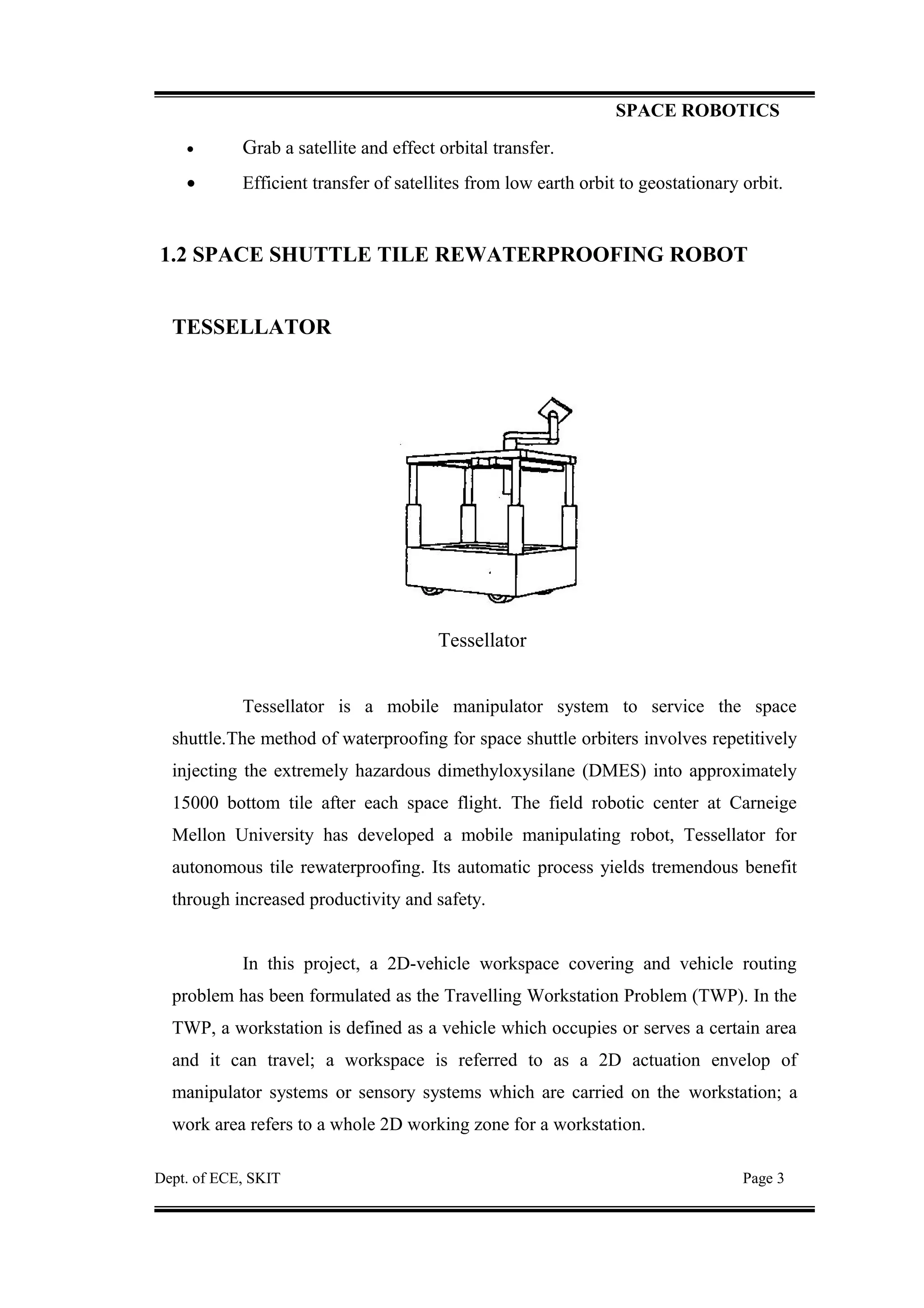
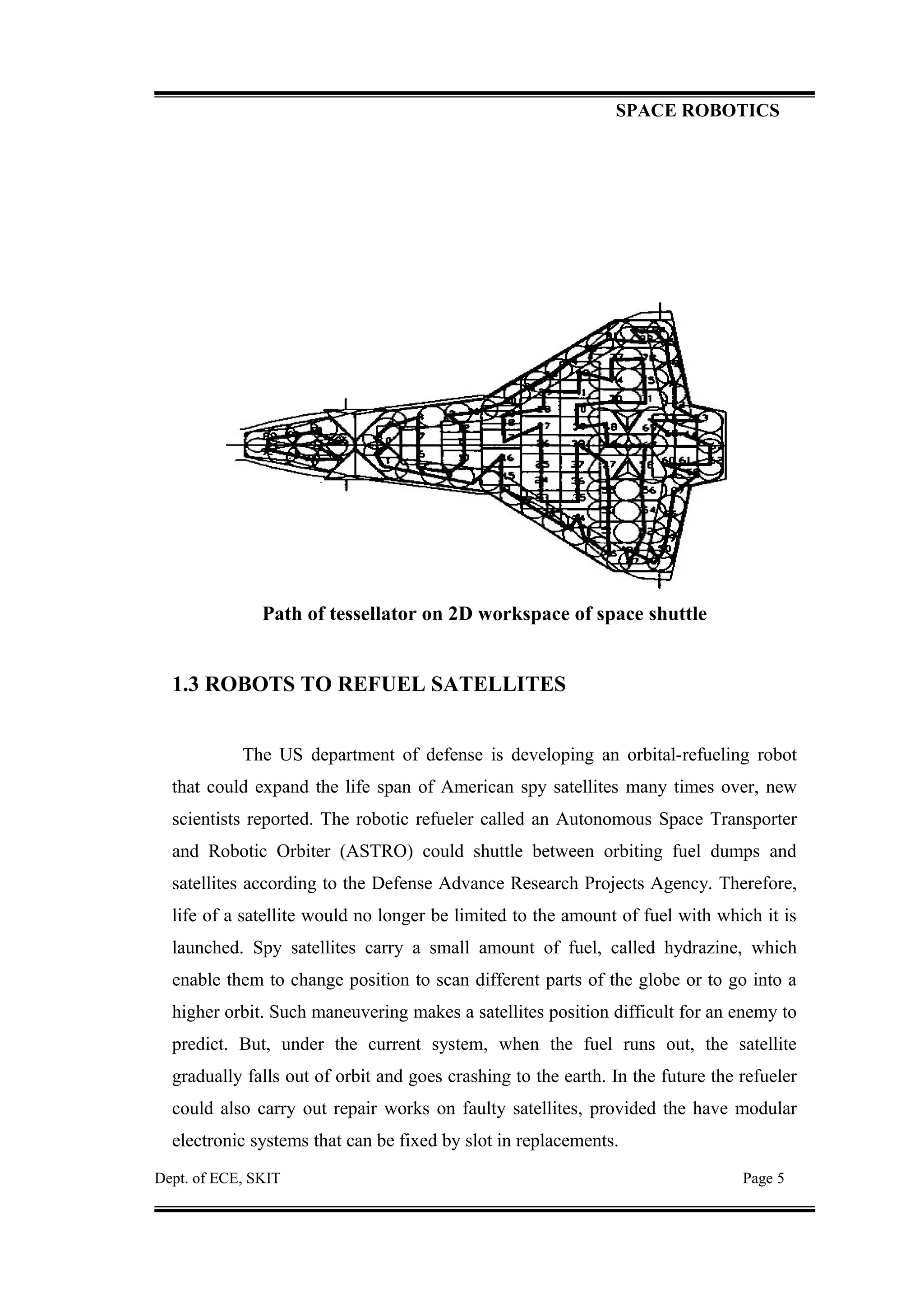
2) Examples of space robot applications like satellite assembly, maintenance, resupplying space stations. It also discusses a specific robot called Tessellator used for repairing space shuttle tiles.
3) The challenges of verifying and testing space robots to ensure reliability given the inability to fully simulate zero gravity conditions on Earth. Common testing methods like using air bearings or water immersion are described.


![Fronczek joseph[1]](https://cdn.slidesharecdn.com/ss_thumbnails/fronczekjoseph1-140901115751-phpapp02-thumbnail.jpg?width=640&height=640&fit=bounds)


