Downloaded 314 times

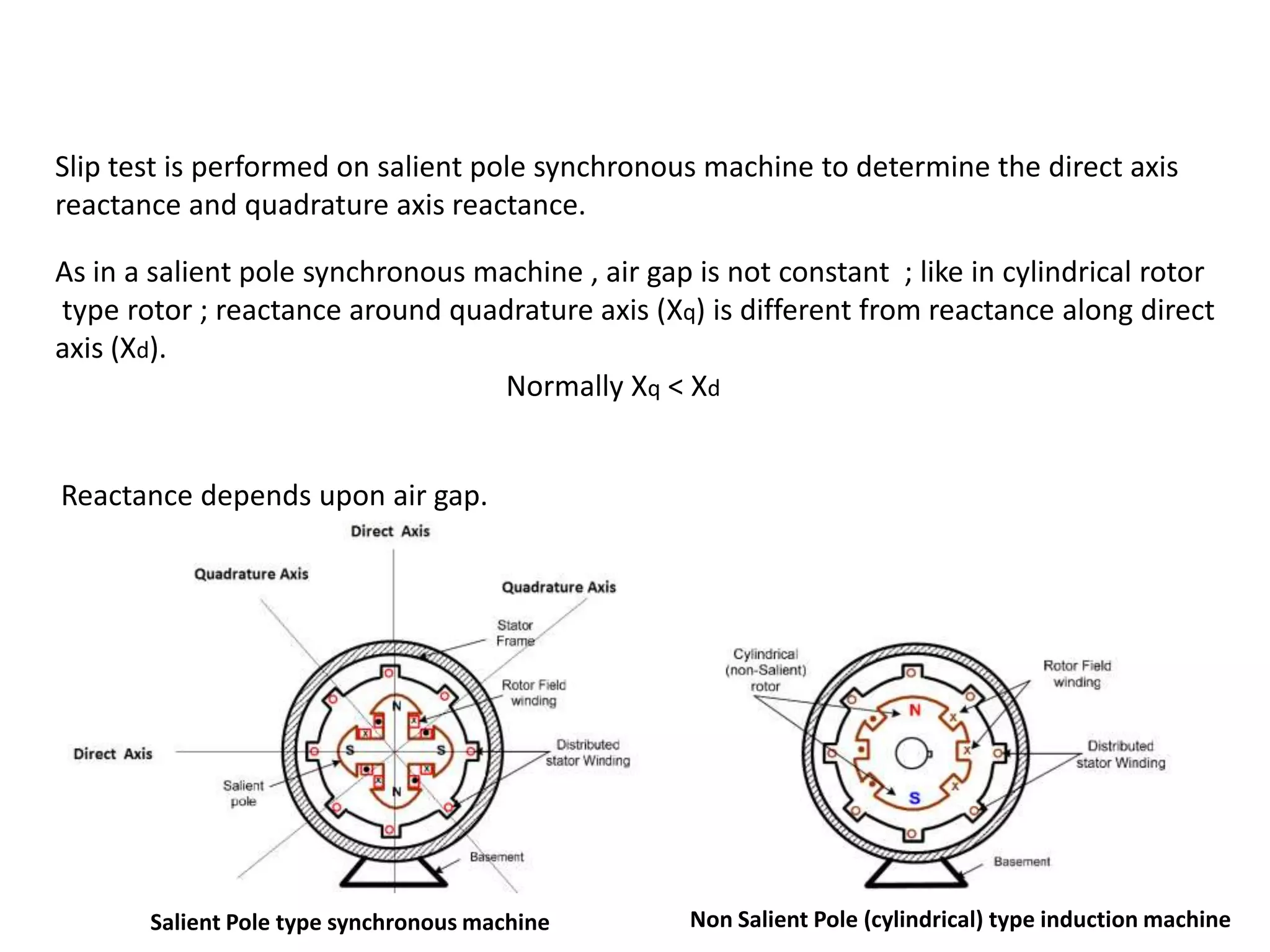
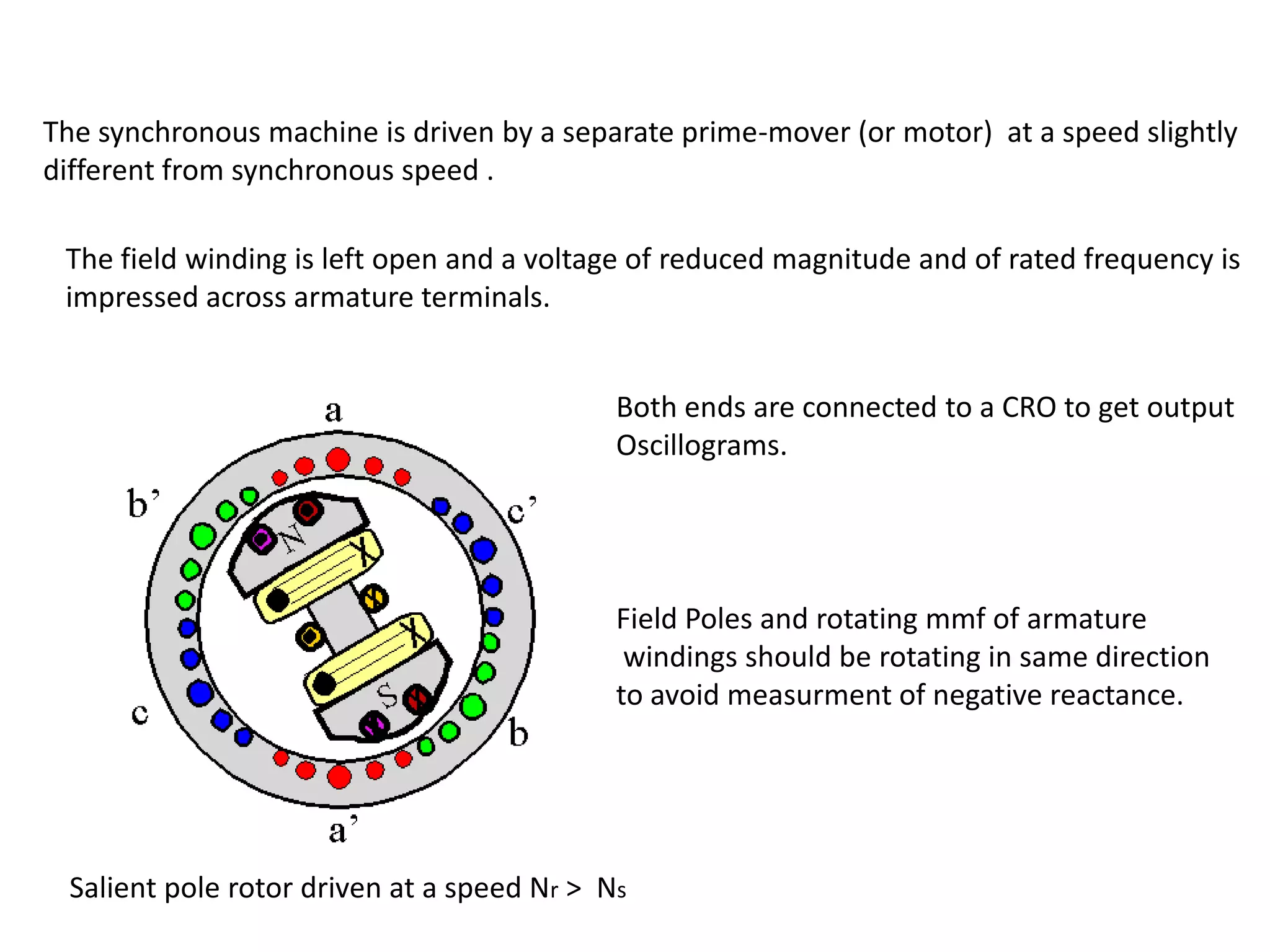


This document discusses performing a slip test on a salient pole synchronous machine to determine the direct and quadrature axis reactances. [1] The test involves driving the machine at a speed slightly less than synchronous speed and measuring voltages and currents along the direct and quadrature axes. [2] This allows calculating the direct axis reactance Xd when the magnetic fields are aligned, and the quadrature axis reactance Xq when they are 90 degrees out of phase. [3] Oscilloscope measurements provide more accurate results than voltmeter-ammeter methods.