Downloaded 536 times

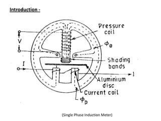
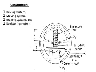
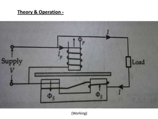
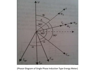
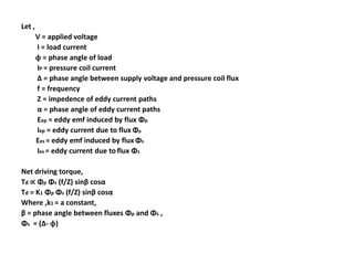
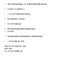
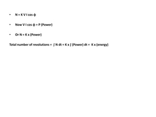

The document summarizes the construction and working of a single phase induction type energy meter. It consists of a driving system, moving system, braking system and registering system. The driving torque is proportional to the supply voltage, load current and their phase difference, causing the disk to rotate. The number of rotations is proportional to the energy consumed. Potential errors include incorrect fluxes/phase angles and friction changes. Adjustments include preliminary light load and creep adjustments to calibrate the meter.


