This document provides specifications for the SK6812 integrated light source intelligent control chip-on-top SMD type LED. Key details include:
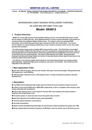
- It is a 0.2W top SMD type LED with integrated control circuit and RGB chips.
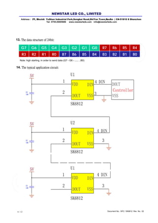
- Each LED acts as a pixel that can be individually controlled for color and intensity via a digital interface.
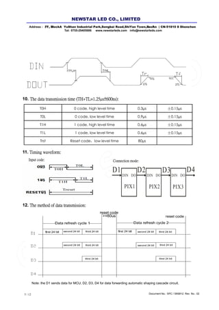
- It uses a 24-bit data protocol for signal transmission between LEDs connected in a chain.
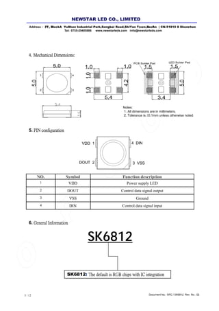
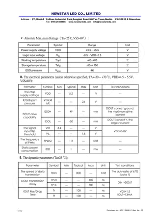
- Specifications include electrical parameters, timing diagrams, data structures, and packaging.


![5G Explained! A High Level Overview [Introduction]](https://cdn.slidesharecdn.com/ss_thumbnails/5gexplainedahighleveloverview-260119165306-cc137a3e-thumbnail.jpg?width=640&height=640&fit=bounds)


