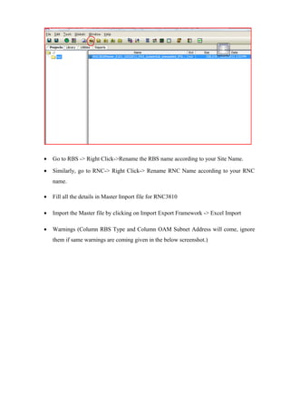
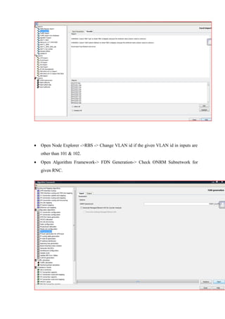
SlideShare a Scribd company logo
1 of 75
TABLE OF CONTENTS
1. ACKNOWLEDGMENTS
2. INTRODUCTION
3. INTRODUCTION TO ERICSSON
4. BASICS OF TELECOMMUNICATIONS
5. EVOULUTION IN TELECOMMUNICATION
6. WCDMA-UNIVERSAL MOBILE COMMUNICATION,UMTS
7. LONG TERM EVOLUTION,4G
ACKNOWLEDGMENTS
I take this opportunity to express my gratitude to the people who have been instrumental in
the successful completion of this project.
I would like to thank Mr. Pallav Tyagi, Senior Manager, Ericsson, Noida for his immense
contribution in the course of these 6 weeks throughout which his efforts have been
remarkable.
I am also grateful to Ms. Supriya Pachani, ATND/DT Engineer, Ericsson who helped me in
the successful completion of this project. I thank beyond words Mr. Chetan Bhauser, Mr.
Raghav Kocchar and Ms Nidhi Dwivedi for their continuous support and guidance.
INTRODUCTION
I walked into Ericsson’s office in Noida knowing that this is where all, or at least most of
AITTM aspires to be working after finishing their 4 years of education. I was proud to have
that little advantage of knowing of what I would be walking into if I ever got placed here, I
was proud to be getting the Ericsson experience having heard so much about it from our
seniors and in our 3 years of college education so far.
I walked in, not only to learn what they taught me but also imbibe everything they possibly
had to offer, the office culture, the working environment and ethics. This summer internship
was more than just learning about 3G technology. We all have come across 3G in our lives in
some way or the other, may it be using it I our phones or reading about it in the papers.
This, to me, was about becoming a professional and not be a student anymore. We’ll all be
students at heart, always learning something new, but its time to ease into that professional
life as well. The life of an excellent and employed telecom engineer.
And I am proud to say that i gave my full dedication and devotion to this training and learned
everything that Ericsson had to offer. This experience has been most enlightening and
educating and also taught me a lot about not just where I want to work but how i want to
work.
At Ericsson, I was placed under the CA Access group in the RNAM department. A network
has two parts to it, namely Access and Core. Core mainly deals with signaling part whereas
Access with the radio branch. Access basically handles the transmission details of the
organization. RNAM’s elementary profile reads design networks and solutions for North
America region.
INTRODUCTION TO ERICSSON
Ericsson is a world-leading provider of telecommunications equipment and related services to
mobile and fixed network operators globally. Over 1,000 networks in more than 175
countries utilize Ericsson’s network equipment and 40 percent of all mobile calls are made
through its systems. It is one of the few companies worldwide that offer end-to-end solutions
for all major mobile communication standards.
Its origin dates back to 1876. The parent company was Telefonaktiebolaget LM Ericsson
(company registration number 556016-0680). Its headquarters are located, and the Board of
Directors is seated, in Stockholm, Sweden.
Ericsson, the world leader in telecommunications has been associated with the Indian telecom
industry for over 100 years. Ericsson supplied its first product to India - manual switchboards
to the Government - in 1903. Since then, it has powered virtually every facet of
telecommunications in India, right from handsets to entire networks.
Enjoying a unique position of being an end-to-end solutions provider, with the ability to offer
complete mobile solutions on a turnkey basis, Ericsson has been successfully partnering the
growth of the country’s cellular revolution since 1994, when cellular services were first
launched in India.
With its powerful portfolio of offerings that comprise mobile and fixed network infrastructure
and broadband and multimedia solutions for operators, enterprises and developers, Ericsson
today has a pan India presence and provides mobile networks to all major Government and
private operators. It is the leader in the wireless market with over 34% market share.
Ericsson works with all the leading mobile operators in India and has been part of their
growth journey. Ericsson’s customers include Aircel, BSNL, Bharti Group, Idea Cellular,
Vodafone, MTNL, Reliance Telecom, Tata Teleservices and VSNL.
Ericsson’s long and illustrious history is reflective of its commitment towards India and the
future of the Indian telecommunications industry. Ericsson is convinced about the Indian
telecom industry’s rapid evolution, backed by strong demand, positive regulatory measures
and increased affordability – all of which have been instrumental in fuelling the growth of
telecommunications in the country. Ericsson employs about 10,000 people in India, across 25
locations.
HISTORY OF INNOVATIONS
• 1878- Telegraph to telephone
• 1923 - Manual switching to automatic switching
• 1968 - Electro mechanics to computer control
• 1981 - Fixed communications to mobile communication
• 1991 - Analog (1G) to digital (2G) mobile technology
• 1998 - Integration of voice and data in mobile networks
• 2001- Launch of WCDMA/3G networks in Western Europe
• 2006- Launch of HSPA mobile broadband globally
• 2009- First commercial LTE network launched
• 2010- Sales of mobile broadband took off
VISION
To be the Prime Driver in an all-communicating world.
This means a world in which all people can use voice, data, images and video to share ideas
and information whenever and wherever they want.
CORE VALUES
Respect, professionalism and perseverance are the values that are the foundation of the
Ericsson culture, guiding us in our daily work - how we relate to people and how we do
business.
ERICSSON GLOBAL SERVICES CENTRE
PURPOSE
Global Service Centres (GSC) established as service excellence organizations, using leading
processes, methods and tools designed for remote delivery (e.g. managed operations, remote
project activities, etc) and driven by scale, standardization, productivity and innovation.
RESPONSIBILITIES
› The Global Service Centers are responsible for
delivery of remote/ centralized services
– Global Network Operation Center (GNOC)
› Managed Operations
– Global Customer Support
› Centralized Customer Support Request (CSR) Handling
› Emergency Customer Support
› Software Update Management (SUM)
– Remote Service Delivery
› Application Development and Maintenance and
Customer Adaptations ( ADM/CA)
› Configuration
› Design & Optimization
› Integration
› Planning & Engineering
› Solution Analysis
› Software Deployment Preparation (SWDP)
GLOBAL SERVICES CENTRE- INDIA
• Operates in 5 locations across India:
– Noida, Gurgaon, Bangalore, Kolkata and Chennai
• Areas of responsibilities:
– Global Network Operations
– Global Customer Support
– Remote Delivery
• Established campus for recruitment and training
• Ericsson’s largest Global Services Center
• Global Service Center Manager: Mats Agervi
• Executive Assisstant: Anju Tomar
• Internal communication: Abhijit Roy
• Finance and support: Debashish Roy Chowdhury
• Technology and quality: Jan-Erik Gustavsson
• Tactical planning and implementation: Liam Coffey
• HR and organization: Priyanka Anand
• Revenue management R and D: Hedwig Baars
• Software delivery: Manoj Kumar Sharma
• Operations, Engineering and Access: Abhay Vaish
CHAPTER 1
BASICS OF TELECOMMUNICATION
Telephony involves the transmission of sound over distances. This sound is most often
voice, although it can also be music or data. The public telephone network constructed during
the last century was built primarily to carry voice. We know, however, that individuals and
businesses today can transmit voice, data, images, video, and other types of information over
this network. Before it is discussed how transmission occurs electronically, let’s consider the
nature of sound and how it propagates.
Sound is produced by vocal cords, musical instruments, airplanes, the wind, and millions of
other sources. Sound is created by regions of high and low pressure in the surrounding air
that stimulates the inner ear to generate impulses that the brain recognizes as sound. Air is the
transmission medium for sound. Transmission occurs mechanically as the regions of high and
low pressure rapidly moves through the air away from a source, in the same way that ripples
move across a pond. As in all mechanical transmission, sound incurs losses as it moves away
from the source—that is, it becomes softer. This is because its energy, which at first is
concentrated, spreads out over a larger area as the pressure wave moves away from the source
—again, think of ripples. It also becomes softer due to the inelastic way that air molecules
collide with one another. These losses limit the distance over which intelligible speech can be
sent through the air. However, sound can be amplified as it leaves the source.
The invention of the telephone set in 1876 heralded the beginning of our ability to send voice
conversations over long distances. It provided a way to convert mechanical energy to
electrical energy and back again. This conversion technique meant that a signal that modeled
the pressure wave of voice could be sent over copper wires and periodically amplified to
overcome electrical losses. This enabled transmission across hundreds or thousands of miles,
rather than just the few thousand feet allowed by pure mechanical transmission over air.
One type of telephone handset contains a microphone powered by a constant voltage from the
network. This microphone is filled with carbon granules and is in series with the battery
potential. Its resistance varies as the voice pressure wave alternately compresses and releases
the granules. The circuit obeys Ohm’s Law relating voltage, current, and resistance (voltage =
current ´ resistance). Therefore, the voice pressure wave produces a varying current signal
that models the pressure wave.
This electrical signal can be transmitted over the network to another telephone set, where it
encounters the speaker in the receiver. In some of these devices, the varying current signal
alters the strength of an electromagnet that sets up vibrations in a thin metal disc. These
vibrations cause a varying pressure wave to occur in the air between the receiver and a
person’s ear. This pressure wave is then converted to sound by the ear and brain. The
telephone set thus gives us the transducer needed to convert mechanical energy to electrical
energy and back again. While the signal is in an electrical form, we can transmit it over long
distances.
One could create a simple telephone network by running a line between each person’s
telephone and the telephone of every other subscriber to whom that person might wish to talk.
However, the amount of wire required for such a network would be overwhelming.
Interestingly enough, the first telephone installations followed exactly this method; with only
a few telephones in existence, the number of wires were manageable. As the telephone caught
on, this approach proved to be uneconomical.
Therefore, the telephone industry of today uses a switched network, in which a single
telephone line connects each telephone to a centralized switch. This switch provides
connections that are enabled only for the period during which two parties are connected.
Once the conversation/ transmission is concluded, the connection is broken. This switched
network allows all users to share equipment, thereby reducing network costs. The amount of
equipment that is shared by the users is determined by the traffic engineers and is often a cost
tradeoff. Indeed, a guiding principle of network design is to provide a reasonable grade of
service in the most cost-effective manner. The switched network takes advantage of the fact
that not everyone wants to talk at the same time.
The three basic elements of a switched system are:
• Local loop- The direct connection from each telephone to a local switch is called the
local loop (or line) that, in the simplest case, is a pair of wires.
• Trunk- These are switch-to-switch connections.
• Central switch- The central switch is the core network element that establishes
temporary connections between two subscribers.
DEFINING TELECOMMUNICATION
Many people call telecommunication the world’s most lucrative industry. Add cellular and
personal communication system users, there are about 1800 million subscribers to
telecommunication services worldwide (1999). Annual expenditures on telecommunications
may reach 900,000 million dollars in the year 2000.
Webster’s calls it communications at a distance. The IEEE dictionary defines
telecommunications as “the transmission of signals over long distance, such as by telegraph,
radio or television.”
Some take the view that telecommunication deals only with voice telephony, and the typical
provider of this service is the local telephone company. Telecommunication encompasses the
electrical communication at a distance of voice, data, and image information (e.g. TV and
facsimile). These media, therefore, will be a major topic. The word media (medium, singular)
also is used to describe what is transporting telecommunication signals. This is termed
transmission media. There are four basic types of medium: (1) wire-pair, (2) coaxial cable,
(3) fiber optics, and (4) radio.
In industrialized nations, the telephone is accepted as a way of life. The telephone is
connected to the public switched telecommunications network (PSTN) for local, national, and
international voice communications. These same telephone connections may also carry data
and image information (e.g., television).
Telecommunication systems have three units
• A transmitter that takes information and converts it to a signal.
• A transmission medium, also called the “physical channel” that carries the signal.
• A receiver that takes the signal from the channel and converts it back into usable
information.
Telecommunication over telephone lines is:
• Point-to-point communication: between one transmitter and one receiver.
• Broadcast communication: between one powerful transmitter and numerous low-
power, but sensitive receivers.
Communications signals can be either by analog signals or digital signals. Analog signal
varied continuously with respect to the information. In a digital signal, the information is
encoded binary language. During the propagation and reception, the information contained in
analog signals will inevitably be degraded by noise. And the desired output of a transmitter is
noise-free for all practical purposes.
Communications networks
A communications network is a collection of transmitters, receivers, and communications
channels that send messages to one another. Routers transmit information to the correct users.
An analog communications network use switches to connect to form a connection between
the two users. Communication network or switches require repeaters to amplify or recreate
the signal when it is being transmitted over long distances.
Communication between two users:
The caller is connected to the person he wants to talk to by switches at various telephone
exchanges. The switches form an electrical connection between the two users and the setting
of these switches is determined electronically when the caller dials the number. Once the
connection is made, the caller’s voice is transformed to an electrical signal using a small
microphone in the caller’s handset. This electrical signal is then sent through the analog
network to the user at the other end where it is transformed back into sound by a small
speaker in that person’s handset. The separate electrical connection works in reverse to
convert sound to electrical.
PSTN (public switched telephone network):
The public switched telephone network (PSTN) it is world’s public circuit-switched
telephone networks. It is a worldwide net of telephone lines, fiber optic cables, microwave
transmission links, cellular networks, communications satellites, and undersea telephone
cables connected by switching centers, which allows any telephone in the world to
communicate with any other. The PSTN is entirely digital in its core and includes mobile as
well as fixed telephones.
TELECOMMUNICATION ASSOCIATIONS
This section provides a list of major standards bodies that affect telecommunications, such as
the ITU-T, ISO, ANSI, ATIS, EIA, TIA, and IEEE. A public telephone network in which
equipment from various vendors can be attached requires interfaces and standards that
specify rules for obtaining service. Similarly, standards are also required for data networking.
The following list identifies several important standards bodies:-
• International Telecommunication Union-Telecommunication Standardization Sector
(ITU-T) -- A United Nations–sponsored agency for defining telecommunications
standards.
• International Organization for Standardization (ISO) -- An international organization
that produces standards for industry and trade (e.g., film speed, screw threads, and
telecommunications).
• American National Standards Institute (ANSI) -- Publishes standards produced by
accredited committees, such as T1 for telecommunications.
• Alliance for Telecommunications Industry Solutions (ATIS) -- Sponsored by the
telephone carriers. Sponsors the T1 committee for development of
telecommunications standards.
• Electronics Industry Association (EIA) -- Standards body representing manufacturers
that produce standards such as the EIA-232 interface.
• Institute of Electrical and Electronics Engineers (IEEE) -- Sponsors the 802
committee that has developed many of the local area networking standards.
• The European Telecommunications Standards Institute (ETSI) -- Standards body that
represents the telecommunications companies from 52 countries inside and outside of
Europe.
CHAPTER 2
EVOLUTION IN TELECOMMUNICATION
INTRODUCTION
The first generation of cellular networks, known as 1G, consisted of analog systems capable
of carrying only voice. These first mobile phone systems were in use from the late 1970s
through to the 1980s, and were just recently ‘retired’. In the 1990’s, the second generation
(2G) networks were launched — including GSM, TDMA and CDMA. 2G network replaced
the analog processing of the 1G networks with digital processing, enabling the wireless
transmission of voice as well as data. The 2G digital cellular networks expanded on the
voice-only services of 1G network, enabling a variety of new features such as push-to-talk,
short messaging service (SMS), conference calling, caller ID, voicemail and simple data
applications like email messaging and web browsing. These networks are still in existence
today, providing voice service to the majority of today’s cell phone users. To address the
world’s ‘need for speed’, carriers continued to develop 2G networks, giving birth to an
interim generation of cellular networks with a significant increase in bandwidth over 2G
networks- the 2.5G networks.
Recently, we have seen a new technology in the area of telecom. This new technology’s
named 3G and it is a new revolution in the area of telecom.
The 3G networks are the next step in the quest for speed, increasing bandwidth to speed, with
a range of 144 Kbps to 2+ Mbps. As a result, 3G can provide support for more demanding
multimedia applications, such as video conferencing, voice-over-iP (VOiP), full motion video
and streaming music (for example, to support television programming and satellite radio),
while also offering faster Web browsing and faster file downloads.
UMTS is the European vision of 3G.UMTS, or universal mobile telecommunication systems
is an upgrade from GSM via GPRS or EDGE. UMTS network architecture consists of three
domains:
• Core Network (CN) : To provide switching, routing and transit for user traffic.
• UMTS Terrestrial Radio Access Network (UTRAN): Provides the air interface access
method for User Equipment.
• User Equipment (UE).
4G looms in the future, and includes long term evolution or LTE, (ultra mobile broadband)
UMB and potentially Wi-max. 4G networks are defined as networks that will offer speeds
from 100 Mbps to 1 Gbps, providing robust performance for the most bandwidth intensive
applications, such as high quality streaming video.
HISTORY OF GSM
• 1G : Based on Advanced Mobile Phone Service (AMPS)
Launched in the year 1983 using a bandwidth of 800-900 MHz and a channel bandwidth of
about 30 MHz. It maximized the concept of frequency reuse, by reducing the radio power
output. Frequency reuse means restructuring mobile telephone system architecture into
cellular concepts. It assigns each cell in a group of radio channels within small geographical
area and the coverage area is called a footprint. This technology of 1G was used mostly
throughout the world, i.e USA, South America, China and Australia. The limitations of this
technology were low calling capacity, poor data communication, limited spectrum, minimal
privacy and inadequate fraud protection.
• 2G: Based on Digital Advanced Mobile Phone Service (D-AMPS); Global
System for Mobile (GSM); Code Division Multiple Access (CDMA).
Core division multiplexing technique, CDMA is a multiplexing technique that was patented
by Qualcomm and had a bandwidth of 2.5 MHz.
COMPONENTS OF A GSM NETWORK
A mobile station (MS) is used by mobile subscriber to communicate with other mobile
networks. There are several types of mobile stations that help the subscribers to make and
receive calls. An MS essentially has two parts, namely a mobile handset and a subscriber
identity module (SIM).
SIM is a removable module put into a handset. It has a unique code called the International
Mobile Subscriber Identity, IMSI. This contains the entire customer related information. A
SIM consists of a built in micro-computer and memory, i.e
ROM (read only memory)= 6-16 kB
EEPROM (electrically erasable programmable read only memory)= 3-8 kB
RAM (read access memory)= 128-256 bytes
International mobile subscriber identity, IMSI is a unique 15 digit code stored in the SIM that
identifies user on the GSM network. It has three components:
• Mobile country code, MCC – 3 digit code
• Mobile network code, MNC – 3 digit code
• Mobile subscriber identity code, MSIC – not more than 9 digits code
A temporary IMSI, TMSI is a pseudo random number generated from IMSI number. It is
utilized in order to remove the need to transmit the IMSI over-the-air, which helps to keep
IMSI more secure.
GSM stands for Global System for Mobile Communication. A GSM mobile station consists
of mobile terminal and a subscriber identity module(SIM). Here, the subscriber is separated
from the mobile terminal and subscriber information is stored as ‘Smart Card’ SIM. The
advantage of this is security or portability to subscribers.
A GSM network is divided into two systems. Each of these systems are compromised of a
number of functional units, which are individual components of the mobile network. The
GSM subsystems are:
• Network subsystem- it includes the equipments and functions related to
end-to-end call.
• Radio subsystem- it includes the equipments and functions related to the
management of the connections on the radio path.
• Operation and Maintenance subsystem- it includes the operation and
maintenance of GSM equipment for radio and network interface.
The access entities of GSM are switching system (SS) and base station system (BSS).
Switching systems (SS): Responsible for call processing and subscriber related information.
Functional units:-
• Mobile services switching center (MSC)
• Home location register (HLR)
• Visitor location register (VLR)
• Authentication center (AUC)
• Equipment identity register (EIR)
Base station system (BSS): Performs radio related functions. It has two functional units:-
• Base station controller (BSC)
• Base transceiver station (BTS)
Operation and Maintenance centre (OMC) performs operation and maintenance tasks for
networks, such as monitoring network traffic and network alarms. OMC has access to both
SS and BSS.
Mobile Service Switching System (MSC) is a primary node in GSM. It controls calls to and
from the mobile station (MS). Primary functions of MSC includes:-
• Manages location of mobile
• Switches calls
• Manages security features
• Controls handovers between calls.
*When a call moves from one cell to another, the radio channels used by the cells are
different so the call is either transferred or dropped. Since the call can’t be dropped,
HANDOVERS are created. In this case, calls are automatically transferred from one radio
channel to another. The user doesn’t notice a handover.
• Resource management
• Collects all billing data and sends to billing system
Functions of Switching systems (SS):-
1) Switching and call routing
• MSC controls call setup, supervision and release.
• It may interact with other nodes to successfully establish a call. Includes
routing of calls from mobile stations to other networks, eg: PSTN.
2) Charging
• MSC contains functions for charging mobile calls.
• Information about a particular charge rates to apply to call at any given time or
any given destination. During a call, this information is recorded. After the call,
this information is stored for output to billing center.
3) Service provisioning
• Supplementary service provided and managed by MSC.
• SMS service also handled by the MSC.
GSM FREQUENCY BANDS:
• GSM 900-
The original frequency band specified for GSM was 900 MHz. Most GSM networks
worldwide use this band. In some countries an extended version of GSM 900 can be
used, which provides extra network capacity. This extended version of GSM is called
E-GSM, while the primary version is called P-GSM.
• GSM 1800-
In 1990, in order to increase completion between operators, the United Kingdom
requested the start of a new version of GSM adapted to the 1800 MHz frequency band.
Licenses have been issued in various countries and networks are in full operation. By
granting licences for GSM 1800 in addition to GSM 900, a country can increase the
number of operators. In this way, due to increased competition, the service to
subscribers is improved.
Each band is divided into 200kHz carriers, as with GSM -900. Therefore 374 carriers are
available within each of the up and down link bands (allowing for guard bands). Channel
numbers are in the range 512-885 (ARFCNs).
The channel pair allocation has been arranged such that the two frequencies comprising a
channel pair are 95Mhz apart.
• GSM 1900-
In 1995, the personal communication system, PCS concept was specified in the
United States. The basic idea is to enable ‘person-to-person’ communication rather
than ‘station-to-station’. PCS does not require that such services be implemented
using cellular technology, but this has proven to be the most effective method. The
frequencies available for PCS are around 1900 MHz.
• GSM-450 Spectrum
The GSM-450 standard has grown from a study undertaken to evaluate a digital standard to
replace the widespread analogue NMT-450 systems. The
450MHz band has a number of advantages over existing GSM bands, not least of which is the
increased coverage per cell (up to 120km) and hence a lower cell count. It can also provide
valuable additional capacity.
GSM Multiple Access Techniques
Multiple Access Techniques
• Purpose: to allow several users to share the resources of the air interface in one cell
• Methods:
• FDMA - Frequency Division Multiple Access
• TDMA - Time Division Multiple Access
• CDMA - Code Division Multiple Access
Multiple access techniques are essential to allow more efficient use of the radio spectrum. 1st
generation systems used only FDMA so that a complete radio carrier was allocated to a user
throughout their call. This made poor use of the spectrum, but was all that was possible with
an analog system.
Frequency Division Multiple Access (FDMA)
• Divide available frequency spectrum into channels each of the same bandwidth
• Channel separation achieved by filters:
• Good selectivity
• Guard bands between channels
• Signalling channel required to allocate a traffic channel to a user
• Only one user per frequency channel at any time
• Used in analog systems, such as AMPS, TACS
• Limitations on:
• Frequency re-use
• Number of subscribers per area
Time Division Multiple Access (TDMA)
• Access to available spectrum is limited to timeslots
• User is allocated the spectrum for the duration of one timeslot
• Timeslots are repeated in frames
TDMA became possible with digital systems such as GSM in which the data stream could be
divided into bursts and allocated to a timeslot. By sharing access to the spectrum, the traffic
capacity of the system is enhanced. GSM uses both FDMA to provide carriers and TDMA to
share access to the carriers.
GSM PROTOCOLS
• Protocols are needed whenever systems pass information from one to another
• A protocol is just a set of rules that both sides agree on so that meaningful communication
can take place
4.1 The ISO 7-layer OSI Model
Development of the Open Standards Interconnection (OSI) reference model was started in
1983 by a number of major computer and telecommunications companies. It was eventually
adopted as an international standard by the
International Standards Organisation (ISO) and is currently embodied within the ITU-TS
X.200 Recommendation.
The model comprises 7 layers which define various functions involved in establishing and
servicing end-to-end communications circuits across a network. These 7 layers are generally
viewed in two blocks;
• Application Functional Layers. These are layers 4-7 of the OSI Model and relate to the end-
to-end functions between two or more users at the periphery of a network.
• Network Functional Layers. These are layers 1-3 of the OSI Model and refer to the
functions required to transport data across a network.
Layer 7: The application layer...This is the layer at which communication partners are
identified, quality of service is identified, user authentication and privacy are considered, and
any constraints on data syntax are identified.
(This layer is not the application itself, although some applications may perform application
layer functions.)
Layer 6: The presentation layer...This is a layer, usually part of an operating system, that
converts incoming and outgoing data from one presentation format to another (for example,
from a text stream into a popup window with the newly arrived text). This layer is sometimes
called the syntax layer.
Layer 5: The session layer...This layer sets up, coordinates, and terminates conversations,
exchanges, and dialogs between the applications at each end. It deals with session and
connection coordination.
Layer 4: The transport layer...This layer manages the end-to-end control (for example,
determining whether all packets have arrived) and error-checking. It ensures complete data
transfer.
Layer 3: The network layer...This layer handles the routing of the data
(sending it in the right direction to the right destination on outgoing transmissions and
receiving incoming transmissions at the packet level). The network layer does routing and
forwarding.
Layer 2: The data-link layer...This layer provides synchronization for the physical level and
does bit-stuffing for strings of 1's in excess of 5. It furnishes transmission protocol knowledge
and management.
Layer 1: The physical layer...This layer conveys the bit stream through the network at the
electrical and mechanical level. It provides the hardware means of sending and receiving data
on a carrier.
4.2 GSM Protocols Overview
Within a GSM network, different protocols are needed to enable the flow of data and
signalling between different GSM subsystems. The following diagram shows the interfaces
that link the different GSM subsystems and the protocols used to communicate on each
interface.
As GSM is a transport network, it is primarily only the lower 3 layers of the
OSI Model that are defined in the GSM Recommendations.
As GSM is predominantly a transport network it is less concerned with the end-to-end user
application layer (layers 4-7). Therefore this section of the course notes looks specifically at
the protocols used within GSM at layers 1-3.
GSM Protocol Layers
• GSM protocols are basically divided into three layers:
Layer 1: Physical layer
• Enables physical transmission (TDMA, FDMA, etc.)
• Assessment of channel quality
• Definition of physical links (e.g radio, PCM30 ISDN etc)
• Error detection (based on line coding)
Layer 2: Data link layer
• Multiplexing of one or more layer 2 connections on control/signalling channels
• Error detection (based on HDLC)
• Flow control
• Transmission quality assurance
• Routing
Layer 3: Network Layer
• Connection management
• Management of location data
• Subscriber identification
• Management of Services
Layer 1 Services
The Physical Layer (Layer 1) contains all the functions necessary for the transmission of bit
streams over the physical medium. It provides a transport service for the GSM logical
channels. Services offered at Layer 1 include:
• Access Capabilities. Layer 1 carries out the cell selection functions for
MSs in idle mode, in cooperation with the Layer 3 Radio Resource (RR) functions.
• Error Detection. Forward and backward error correction is implemented at layer 1 (see
section on speech coding for details). Errored frames are not passed to Level 2 for processing.
• Encryption. Data encryption is also implemented at Layer 1 (see section on GSM security
for details).
Layer 2 Services
Here, the LAPDm protocol is used (similar to ISDN LAPD). LAPDm has the following
functions:
• Connectionless transfer on point-to-point and point-to-multipoint signalling channels,
• Setup and take-down of layer 2 connections on point-to-point signalling channels,
• Connection-oriented transfer with retention of the transmission sequence, error detection
and error correction.
Layer 3 Services
Layer 3 contains the following sublayers which control signalling channel functions (BCH,
CCCH and DCCH):
• Radio resource management (RR). The role of the RR management layer is to establish and
release stable connection between mobile stations (MS) and an MSC for the duration of a
call, and to maintain it despite user movements. The following functions are performed by the
MSC:
• Cell selection,
• Handover,
• Allocation and take-down of point-to-point channels,
• Monitoring and forwarding of radio connections,
• Introduction of encryption,
• Change in transmission mode.
• Mobility management (MM). Mobility Management handles the control functions required
for mobility including:
• Authentication
• Assignment of TMSI
• Management of subscriber location.
• Connection management (CM) is used to set up, maintain and clear call connections. It
comprises three subgroups:
• Call control (CC) - manages call connections,
• Supplementary service support (SS) - handles special services,
• Short message service support (SMS) - transfers brief texts.
Neither the BTS nor the BSC interpret CM and MM messages. They are simply exchanged
between the MSC and the MS using the Direct Transfer
Application Part (DTAP) protocol on the A interface.
RR messages are mapped to or from the Base Station System Application Part (BSSAP) for
exchange with the MS.
CHAPTER 3
WCDMA- UNIVERSAL MOBILE
TELECOMMUNICATION SYSTEM, UMTS
IMPORTANT TERMS
EQUIPMENT USER REGISTER (EIR)
The Equipment Identity Register (EIR) is the logical entity which is responsible for storing in
the network the International Mobile Equipment Identities (IMEIs).
The equipment is classified as "white listed", "grey listed", "black listed" or it may be
unknown
• The white list is composed of all number series of equipment identities that are
permitted for use
• The black list contains all equipment identities that belong to equipment that need to
be barred
• Equipment on the grey list are not barred, but are tracked by the network (for
evaluation or other purposes)
AUTHENTICATION CENTRE (AUC)
The main function of the authentication centre (AUC) is to authenticate the subscribers
attempting to use a network. In this way, it is used to protect network operators against fraud.
The AUC is a database connected to the HLR, which provides it with the authentication
parameters and ciphering keys used to ensure network security.
AUC is a separate entity and physically included in HLR. Authentication key (Ki) and
ciphering key (Kc) are stored in this database. Keys randomly change with each call.
SMS SERVICE CENTRE
The SMS-SC deals with the transfer of short of short text messages. This works on a store
and forward basis.
• CELL
A cell is basic unit of a cellular system. It is defined as the area of radio coverage given by
one base station antenna system. Each cell is assigned a unique number called cell global
identity. In a complete network covering an entire country, the number of cells can be quite
high.
Location area-
A location area is defined as a group cells. Within network, a subscriber’s location is known
by the LA they are in. The identity of LA in which a mobile station (MS) is currently located
is stored in the VLR.
When an MS crosses a boundary from a cell belonging to one LA into a cell belonging to
another LA, it must report its new location to the network.
When an MS crosses boundary within an LA, it does not report its new cell location to the
network.
When there is a call for a MS, a paging message is broadcast within all cells belonging to an
LA.
Mobile Services Switching Centre (MSC) service area-
The Mobile-services Switching Centre (MSC) constitutes the interface between the radio
system and the fixed networks. The MSC performs all necessary functions in order to handle
the circuit switched services to and from the mobile stations. UMTS MSCs can be expected
to be identical in hardware to latest generation GSM MSCs, although with a different
software version.
Public land mobile network (PLMN) service area is the entire set of cells served by one
network operator. It is an area in which an operator offers radio coverage and access to its
network. In any one country, there may be several PLMN service areas, one for each mobile
operator’s network.
FUNDAMENTALS OF RADIO COMMUNICATION
• Radio waves are used as a transmission medium. Time dependent electromagnetic
waves that radiate from source to the environment.
• The radio waves based radio communication is vulnerable to the environmental
factors such as mountains, hill reflectors etc. The radio signal depends on the distance
from the base station, the wave length and the communication environment.
• Disadvantages, or the problems posed are:-
 Multipath propagation phenomenon
 Fading effect
 Radio resource scarcity
• Advantages :-
 Connection in case of non-line of sight
 Fluctuation in the received signal’s characteristics
Factors that affect the radio propagation are:
• Reflection – Collision of an electromagnetic wave with an obstruction whose
dimensions are very large in comparison to the wavelength of the radio wave forms a
reflected radio wave.
• Diffraction, Shadowing effect – Collision of the electromagnetic waves with an
obstruction which is impossible to penetrate.
• Scattering – Collision of radio waves with obstructions whose dimensions are almost
equal to or less than the wavelength of the radio wave.
Radio Channel description:
• To determine the expected signal level at a given distance from transmitter is known
as link budget. For example the covering area, battery life, energy losses are factors
that are kept in mind while designing the link budget.
• Time dispersion is the estimation of the different propagation delays related to the
replicas of the transmitted signal which reaches the receiver.
The basic cellular radio communication principles were taught besides the UMTS user
environment. The principles to be followed for radio communication sates that the public
radio communication should be duplex communication in nature. The signal strength
deteriorates together with distance, and every transmitter can offer only limited amount of
simultaneous radio links to end-users.
UMTS is the European vision of 3G.UMTS, or universal mobile telecommunication systems
is an upgrade from GSM via GPRS or EDGE. UMTS network architecture consists of three
domains:
• Core Network (CN) : To provide switching, routing and transit for user traffic.
• UMTS Terrestrial Radio Access Network (UTRAN): Provides the air interface access
method for User Equipment.
• User Equipment (UE).
UMTS CORE NETWORK
The Core Network consists of:
• A Circuit Switched Domain
• A Packet Switched Domain
Some core network entities may belong to both domains.
CIRCUIT AND PACKET SWITCHED DOMAINS
Advantages:
Simple evolution from GSM/GPRS
Low risk
Early availability
Service continuity
Disadvantages:
Build and manage two networks
Separate engineering and dimension
Great infrastructure cost
Duplicated functions
Shared entities:
CS entities PS entitiesCommon
entities
Home location register, HLR
Authentication centre, AUC
Equipment identity register, EIR
SMS service centre
CIRCUIT SWITCHED DOMAIN
The CS domain deals with circuit switched type of connections and the associated signalling,
i.e. those connections that require a dedicated resource. Entities specific to the CS domain are
MSC, GMSC and VLR.
PACKET SWITCHED DOMAIN
The PS domain deals with packet switched type of connections and associated signalling, i.e.
those that are comprised of concatenations of bits formed into packets, each of which can be
routed independently. Entities specific to the PS domain are SGSN and GGSN.
UMTS SYSTEM AREAS
Location Area
• UEs registered on the CS domain report their position in terms of LA
• UEs in idle mode monitor Location Area Identities (LAIs) and report changes
• Stored in the VLR
Routing Area
• UEs registered on the PS domain report their position in terms of RA
• UEs in both idle and connected mode monitor Routing Area Identities (RAIs) and
support changes
• Stored in the SGSN
UTRAN Registration Area
• Used once a signalling/traffic connection is established
CORE NETWORK
FUNCTIONS OF THE CORE NETWORK:
• Switching
• Service Provision
• Transmission of user traffic between UTRAN(s) and/or fixed network
• Mobility Management
• Operations, Administration and Maintenance
MAJOR ELEMENTS OF THE CORE NETWORK:
• VISITOR LOCATION REGISTER (VLR)
The role of a VLR in a GSM network is to act as a temporary storage location for
subscription information for mobile stations, which are within a particular Mobile Service
Centre (MSC) service area. There is one VLR for each MSC service area. This means that the
MSC does not have to contact the HLR, which may be located in another country. Following
steps take place when a mobile station (MS) moves into a new service area:
 The VLR checks its database to determine whether or not it has a record for
the MS (based on the subscriber’s IMSI)
 When the VLR finds no record for the MS, it sends a request to the
subscriber’s home location register, HLR for a copy of the mobile stations (MS)
subscription.
 The HLR passes the information to the VLR and updates its location
information for the subscriber.
 The HLR instructs the old VLR to delete the information; it has on the mobile
station (MS).
 The VLR stores its subscription information for the MS, including the latest
location and status (idle).
• HOME LOCATION REGISTER (HLR)
A database is in charge of the management of mobile subscribers. A PLMN may contain one
or several HLRs: it depends on the number of mobile subscribers, on the capacity of the
equipment and on the organisation of the network contains:
 Subscription information
 Location information enabling the charging and routing of calls towards the
MSC where the MS is registered
• MOBILE SERVICES SWITCHING CENTRE (MSC)
• GATEWAY MSC
Gateway functionality enables an MSC to interrogate a HLR in order to route a mobile
terminating call. It is not used in calls from mobile stations (MS) to any terminal other than
another mobile station (MS).
For example; if a person connected to the PSTN wants to make a call to a GSM mobile
subscriber-
 The PSTN exchange will access the GSM network by first connecting the call
to a GMSC.
 The GMSC requests call routing information from the HLR. HLR provides
information about which MSC/VLR to route the call to. The same is true for a
call from one mobile station (MS) to another.
GMSC implementation
Any MSC in the mobile network can function as a gateway by integration of the appropriate
software and definition of HLR interrogation information. In effect it then becomes a
GMSC/VLR.
Gateway functions:
 Find and interrogate HLR for roaming number.
 Route the call according to the interrogation.
• SERVING GPRS SUPPORT NODE (SSGN)
It is essentially a router supporting packet data transfer within UMTS. Packet switched data
performs additionally the role of the VLR and contains:
 Subscription information: The IMSI; One or more temporary identities.
 Location information
• GATEWAY GPRS SUPPORT NODE (GGSN)
Acts as a gateway into the packet switched network much as the GMSC
 Subscription information: The IMSI.
 Location information: The SGSN address for the SGSN where the MS is
registered.
UMTS TERRESTRIAL RADIO ACCESS NETWORK (UTRAN) – UMTS
ARCHITECTURE
FUNCTIONS OF UTRAN
• Provision of Radio Coverage
• System access control
• Security and privacy
• Handover
• Radio resource management and control
ELEMENTS OF UTRAN
Radio Network Controller
• Owns and controls radio resources in its domain
• Service Access point for all services that UTRAN provides the CN
Node B
• Acts as the radio base station
• Converts the data flow between the Iub and Uu interfaces
Radio network subsystem (RNS)
A Radio Network Subsystem consists of:
• A single RNC
• One or more Node B’s
• Cells belonging to Node B’s
Radio network controller (RNC)
• Responsible for the use and integrity of the radio resources within the RNC.
• Responsible for the handover decisions that require signalling to the UE.
• Provides a combining/splitting function to support macro diversity between different
Node Bs.
Node B
Logical node responsible for radio transmission/reception in one or more cells to/from the
UE.
• Dual mode Node B can supportFDD and TDD mode
• Not necessarily a single site according to the standards
Most current implementations use a single site.
USER EQUIPMENT (UE)
FUNCTIONS OF USER EQUIPMENT
• Display and user interface
• To hold the authentication algorithms and keys
• User end termination of the air interface
• Application platform
ELEMENTS OF USER EQUIPMENT
• Mobile Equipment- The radio terminal used for radio communication over the Uu
interface
• UMTS Subscriber Identity Module- The smartcard that holds the subscriber identity,
authentication and encryption keys etc
• Terminal Equipment item, that sits with the UE- This carries the application specific
user interface. The interface for the TE may be provided by Bluetooth.
INTERFACES IN UMTS
There are four major new interfaces defined in UMTS
• Iu- The interface between UTRAN and the CN
• Iur- The Interface between different RNCs
• Iub- The interface between the Node B and the RNC
• Uu- The air interface
Uu
Iub
Iur
Iu
CORE
NETWORK
RNC RNC
NODE- B
USER
EQUIPMENT
Iu- THE CORE NETWORK TO UTRAN
There are two parts to the Iu interface:
• Iu-ps connecting UTRAN to the packet switched domain of the core network.
• Iu-cs connecting UTRAN to the circuit switched domain of the core network
No radio resource signalling travels over this interface.
The Iu interface divides the UMTS network into the radio specific UTRAN and the core
network responsible for switching routing and service provision.
Iur- THE INTER RNC INTERFACE
The Iur interface allows soft handovers between Node-Bs attached to different RNCs. It is an
open interface to allow the use of RNCs from different manufacturers. Its functions may be
summarised:
• Support of basic inter-RNC mobility
• Support of Dedicated and Common Channel Traffic
• Support of Global Resource Management
Iu
CORE
NETWORK
RNC
The Iur is the interface between two RNCs. It enables the transport of air interface signalling
between an SRNC and a DRNC. Thus the Iur needs to support:
• Basic Inter RNC Mobility
• Dedicated Channel Traffic
• Common Channel Traffic
• Global Resource Management
Iub - THE RNC TO NODE-B INTERFACE
The Iub is an open interface to allow the support of different manufacturers supplying RNCs
and Node-Bs. Its major functions are:
• Carries dedicated and common channel traffic between the RNC and the Node-B.
• Supports the control of the Node-B by the RNC
The Iub is the interface between the RNC and the Node-B. The Node B effectively performs
relay function between the Iub and the Uu. Thus the Iub needs to carry:
• Layer 2+ signalling between the UE and the UTRAN
• Signalling directly to the Node B
 To control radio resource allocation
 General control of the Node-B
 Operation & Maintenance Functionality
Iub
NODE-B
IurRNC RNC
RNC
Uu- THE AIR INTERFACE
Clearly the Uu must be standardised to allow multiple UE vendors to be supported by a
network. The major functions of the Uu are to:
• Carry dedicated and common channel traffic across the air interface
• Provide signalling and control traffic to the mobile from the RNC and the Node-B
NODE-B
USER
EQUIPMENT
Uu
UMTS ARCHITECTURE
IuR
IuB
IuB
Uu
Cu
MOBILE
EQUIPMENT
ME
UMTS SIM
USIM
UE
NODE B
NODE B
NO
DE B
NODE B
UTRAN
GATEWAY
MOBILE
SWTICHING
CENTRE
GMSC
GATEWAY
GSN
GGSN
CN
HOME LOCATION
REGISTER
HLR
Iu
PLMN,
PSTN,
ISDN
INTER
NET,
X25
Iu-PS
Iu-CS
SERVING
GSN
SGSN
RADIO NETWORK
CONTROLLER
RNC
RADIO NETWORK
CONTROLLER
RNC
MOBILE
SWTICHING
CENTRE
MSC/VLR
UMTS NETWORK DIMENSIONING
Network dimensioning is carried out at the start a project. It is a process through which an
initial estimate of the amount of network equipment and possible configurations are
determined. The inputs to the process can be:
• Spectrum availability.
• License conditions.
• Equipment characteristics.
• Link budget.
• Geographic/Demographic data.
• Market projections.
The outputs of network dimensioning are used for:
• Budgetary purposes.
 Negotiations with vendors.
 Manpower resource estimations.
 Business plans.
 Network rollout plans.
 Negotiations with financial backers.
• License applications.
 Auction price.
 Spectrum requirement / license preference.
• Implementation.
 Rollout Timetable and Resource Requirements
 Coverage strategy.
CHAPTER 4
LONG TERM EVOLUTION, 4G
INTRODUCTION
LTE (an initialism of Long Term Evolution), marketed as 4G LTE, is a standard
for wireless communication of high-speed data for mobile phones and data terminals. It is
based on the GSM/EDGE and UMTS/HSPA network technologies, increasing the capacity
and speed using new modulation techniques. The standard is developed by the 3GPP (3rd
Generation Partnership Project) and is specified in its Release 8 document series, with minor
enhancements described in Release 9.
The world's first publicly available LTE service was launched
by TeliaSonera in Oslo and Stockholm on 14 December 2009. LTE is the natural upgrade
path for carriers with GSM/UMTS networks, but even CDMA holdouts such as Verizon
Wireless, who launched the first large-scale LTE network in North America in 2010, and au
by KDDI in Japan have announced they will migrate to LTE. LTE is, therefore, anticipated to
become the first truly global mobile phone standard, although the use of different frequency
bands in different countries will mean that only multi-band phones will be able to utilize LTE
in all countries where it is supported.
Although marketed as a 4G wireless service, LTE as specified in the 3GPP Release 8 and 9
document series does not satisfy the technical requirements the 3GPP consortium has adopted
for its new standard generation, and which are set forth by the ITU-Rorganization in its IMT-
Advanced specification. The LTE Advanced standard formally satisfies the ITU-
R requirements to be consideredIMT-Advanced.
OVERVIEW
LTE is a standard for wireless data communications technology and an evolution of the
GSM/UMTS standards. The goal of LTE was to increase the capacity and speed of wireless
data networks using new DSP (digital signal processing) techniques and modulations that
were developed around the turn of the millennium. A further goal was the redesign and
simplification of the network architecture to an IP-based system with significantly reduced
transfer latency compared to the 3G architecture. The LTE wireless interface is incompatible
with 2G and 3G networks, so that it must be operated on a separate wireless spectrum.
LTE was first proposed by NTT DoCoMo of Japan in 2004, and studies on the new standard
officially commenced in 2005. In May 2007, the LTE/SAETrial Initiative (LSTI) alliance
was founded as a global collaboration between vendors and operators with the goal of
verifying and promoting the new standard in order to ensure the global introduction of the
technology as quickly as possible. The LTE standard was finalized in December 2008, and
the first publicly available LTE service was launched
by TeliaSonera in Oslo and Stockholm on December 14, 2009 as a data connection with a
USB modem. In 2011, LTE services were launched by major North American carriers as
well, with the Samsung Galaxy Indulge offered by MetroPCS starting on February 10, 2011
being the first commercially available LTE smartphone and HTC ThunderBolt offered by
Verizon starting on March 17 being the second LTE smartphone to be sold
commercially. Initially, CDMA operators planned to upgrade to rival standards
called UMB and WiMAX, but all the major CDMA operators (such
as Verizon, Sprint and MetroPCS in the United States, Bell and Telus in Canada, au by
KDDI in Japan, SK Telecom in South Korea and China Telecom/China Unicom in China)
have announced that they intend to migrate to LTE after all. The evolution of LTE isLTE
Advanced, which was standardized in March 2011. Services are expected to commence in
2013.
The LTE specification provides downlink peak rates of 300 Mbit/s, uplink peak rates of
75 Mbit/s and QoS provisions permitting a transfer latency of less than 5 ms in the radio
access network. LTE has the ability to manage fast-moving mobiles and supports multi-cast
and broadcast streams. LTE supports scalable carrier bandwidths, from 1.4 MHz to 20 MHz
and supports both frequency division duplexing (FDD) and time-division duplexing (TDD).
The IP-based network architecture, called the Evolved Packet Core (EPC) and designed to
replace the GPRS Core Network, supports seamless handovers for both voice and data to cell
towers with older network technology such as GSM, UMTS and CDMA2000. The simpler
architecture results in lower operating costs (for example, each E-UTRAN cell will support
up to four times the data and voice capacity supported by HSPA).
FEATURES
Much of the LTE standard addresses the upgrading of 3G UMTS to what will eventually
be 4G mobile communications technology. A large amount of the work is aimed at
simplifying the architecture of the system, as it transits from the existing
UMTS circuit + packet switching combined network, to an all-IP flat architecture system. E-
UTRA is the air interface of LTE. Its main features are:
 Peak download rates up to 299.6 Mbit/s and upload rates up to 75.4 Mbit/s depending
on the user equipment category (with 4x4 antennas using 20 MHz of spectrum). Five
different terminal classes have been defined from a voice centric class up to a high end
terminal that supports the peak data rates. All terminals will be able to process 20 MHz
bandwidth.
 Low data transfer latencies (sub-5 ms latency for small IP packets in optimal
conditions), lower latencies for handover and connection setup time than with
previous radio access technologies.
 Improved support for mobility, exemplified by support for terminals moving at up to
350 km/h or 500 km/h depending on the frequency band.
 OFDMA for the downlink, SC-FDMA for the uplink to conserve power
 Support for both FDD and TDD communication systems as well as half-duplex FDD
with the same radio access technology
 Support for all frequency bands currently used by IMT systems by ITU-R.
 Increased spectrum flexibility: 1.4 MHz, 3 MHz, 5 MHz, 10 MHz, 15 MHz and
20 MHz wide cells are standardized. (W-CDMA requires 5 MHz slices, leading to some
problems with roll-outs of the technology in countries where 5 MHz is a commonly
allocated amount of spectrum, and is frequently already in use with legacy standards such
as 2G GSM and cdmaOne.)
 Support for cell sizes from tens of metres radius (femto and picocells) up to 100 km
radius macrocells. In the lower frequency bands to be used in rural areas, 5 km is the
optimal cell size, 30 km having reasonable performance, and up to 100 km cell sizes
supported with acceptable performance. In city and urban areas, higher frequency bands
(such as 2.6 GHz in EU) are used to support high speed mobile broadband. In this case,
cell sizes may be 1 km or even less.
 Supports at least 200 active data clients in every 5 MHz cell.
 Simplified architecture: The network side of E-UTRAN is composed only of eNode
Bs
 Packet switched radio interface.
CHAPTER 5
ANTENNA TRAINING NETWORK ENGINEERING
Work done during the week: July 9,2012- July 12,2012
Was explained the New Site Add procedure for IP sites in AT&T for both RNC3810 &
RNC3820. The data helps gather the required Inputs and provides a step by step
procedure to complete the TND using Etran 10.1. It is assumed that the user is familiar
with the concepts of IP, ETRAN, Network Transport Configuration and Network
Transport Design.
1. Tools Used
• Etran 10.1 or 5.8
• Ultra Edit (Text Editor)
• Moshell
• Ericoll – Ericsson collaboration website – where deliverables like Scripts/TND/RND
are stored
• SONAR to fetch Kget
• GMO
2. Prechecks
Prechecks for TND in TND & EDP input file
a) RNC Type
• RNC 3810
• RNC3820
b) RBS Name
c) RBS ID (rbsid*id)
d) VLAN_ID
• 101 & 102 for 1st
Cabinet
• 104 & 105 for 2nd
Cabinet
e) RBS IPs
• Bearer_Subnet_IP
• OAM_Lan_Subnet_IP
f) ETMFX12 Slot
• ES# 3 & 25 for RNC 3810
• ES# 4 & 25 for RNC 3820
g) RNC Subnet IP
3. METHOD OF PROCEDURE
TND for RNC3810
• Open ETRAN 10.1 and load the NCZ file for RNC3810 as attached above in point 2.2
• click on Globals -> Select Project Directory -> Browse to load the NCZ file in Etran.
Double click on NCZ file to load it. It will look like this:
Open Node Explorer by clicking on the highlighted button shown below:
• Go to RBS -> Right Click->Rename the RBS name according to your Site Name.
• Similarly, go to RNC-> Right Click-> Rename RNC Name according to your RNC
name.
• Fill all the details in Master Import file for RNC3810
• Import the Master file by clicking on Import Export Framework -> Excel Import
• Warnings (Column RBS Type and Column OAM Subnet Address will come, ignore
them if same warnings are coming given in the below screenshot.)
• Open Node Explorer ->RBS -> Change VLAN id if the given VLAN id in inputs are
other than 101 & 102.
• Open Algorithm Framework-> FDN Generation-> Check ONRM Subnetwork for
given RNC.
• Open Node Explorer ->RNC -> RBS Remoduling ->Select the correct RNC_Module
-> Select the RBS and move it to the left side and hit apply.
• Information:
ES1 = Module 9
ES2 = Module 11
ES3 onwards = Multiples of 10.
• Click RBS->Right click and Select Set Synch Reference Hosts.
• RBS -> BB -> Fill the Transmission Subrack Position as per according to RBS type.
For Example: RBS3206 = 1-C1, RBS3106 = 2-C2 and so on.
• RBS-> BB1->SCTP ->Select ET IP Hosts ->Select RBS Iub Host 1(x.x.x.x) ->
Apply.
• RBS->IP Hosts ->Remove Control plane by right clicking-> Remove Forward.
• RBS -> Ethernet Link-> Remove 7th Ethernet Slot
• RBS ->Right Click-> Select Set SCTP Hosts for RBS
• RBS -> Right Click->Select Set SCTP Parameters
• RNC-> Right Click -> Select Set SCTP Parameters
• Open Link Explorer ->Select RBS Iub Subnet 1 VLAN 1 -> Select Contained Ports ->
Put the RBS BB-02-07 slot on the left side ->Apply.
• Open Import Export Framework -> Export CCR Export files
• Select your RBS and send to the right side
• In Project name, select P7FP_ETRAN_new and Select ARW_IP, BIT_IP &
Onsite_IP and hit Start.
• Following errors will come, ignore them.
ARW: “Location Error”
BIT: “A2EA & Subrack Errors”
On-Site: “Single-Logon_Servers Errors”
Report- AT&T RAN

More Related Content

What's hot

Welcome To The World Of Phones
Welcome To The World Of PhonesWelcome To The World Of Phones
Welcome To The World Of PhonesMudit Agrawal
 
Marketing - Launching 4G Services in india
Marketing - Launching 4G Services in indiaMarketing - Launching 4G Services in india
Marketing - Launching 4G Services in indiaPankaj Chomal
 
Broadband CA1, Aisling Ryan
Broadband CA1, Aisling RyanBroadband CA1, Aisling Ryan
Broadband CA1, Aisling Ryanaislingnv
 
Bluetooth Presentation
Bluetooth PresentationBluetooth Presentation
Bluetooth Presentationguest664c3f
 
Challenges for routing in wireless sensor networks
Challenges for routing in wireless sensor networksChallenges for routing in wireless sensor networks
Challenges for routing in wireless sensor networksAuwal Amshi
 
Evolution of Commercial Mobile Communications - GPREC TechTalk
Evolution of Commercial Mobile Communications - GPREC TechTalkEvolution of Commercial Mobile Communications - GPREC TechTalk
Evolution of Commercial Mobile Communications - GPREC TechTalkVenkateswar Reddy Melachervu
 
Evolution of mobile technology
Evolution of mobile technology Evolution of mobile technology
Evolution of mobile technology Adnan Khan
 
Cell Phone System Technology Final Report
Cell Phone System Technology Final Report  Cell Phone System Technology Final Report
Cell Phone System Technology Final Report iqra university
 
Future of mobile technology
Future of mobile technologyFuture of mobile technology
Future of mobile technologymktgmobile
 
Paper id 36201521
Paper id 36201521Paper id 36201521
Paper id 36201521IJRAT
 
Li fi alpna singh
Li fi  alpna singhLi fi  alpna singh
Li fi alpna singhAlpnaSingh5
 
How to Build Your Own Nationwide 4G Network (for Dummies)
How to Build Your Own Nationwide 4G Network (for Dummies)How to Build Your Own Nationwide 4G Network (for Dummies)
How to Build Your Own Nationwide 4G Network (for Dummies)Kegan Gan
 

What's hot (20)

Welcome To The World Of Phones
Welcome To The World Of PhonesWelcome To The World Of Phones
Welcome To The World Of Phones
 
Airtel 4 G
Airtel 4 GAirtel 4 G
Airtel 4 G
 
Telecom vertical OEM
Telecom vertical OEMTelecom vertical OEM
Telecom vertical OEM
 
MIS
MISMIS
MIS
 
Marketing - Launching 4G Services in india
Marketing - Launching 4G Services in indiaMarketing - Launching 4G Services in india
Marketing - Launching 4G Services in india
 
5G TECHNOLOGY project report
5G TECHNOLOGY project report5G TECHNOLOGY project report
5G TECHNOLOGY project report
 
Broadband CA1, Aisling Ryan
Broadband CA1, Aisling RyanBroadband CA1, Aisling Ryan
Broadband CA1, Aisling Ryan
 
Bluetooth Presentation
Bluetooth PresentationBluetooth Presentation
Bluetooth Presentation
 
Challenges for routing in wireless sensor networks
Challenges for routing in wireless sensor networksChallenges for routing in wireless sensor networks
Challenges for routing in wireless sensor networks
 
Evolution of Commercial Mobile Communications - GPREC TechTalk
Evolution of Commercial Mobile Communications - GPREC TechTalkEvolution of Commercial Mobile Communications - GPREC TechTalk
Evolution of Commercial Mobile Communications - GPREC TechTalk
 
Telecom OEM
Telecom OEMTelecom OEM
Telecom OEM
 
Telecom industry
Telecom industryTelecom industry
Telecom industry
 
Evolution of mobile technology
Evolution of mobile technology Evolution of mobile technology
Evolution of mobile technology
 
Cell Phone System Technology Final Report
Cell Phone System Technology Final Report  Cell Phone System Technology Final Report
Cell Phone System Technology Final Report
 
Lte workshop
Lte workshopLte workshop
Lte workshop
 
Unit 1
Unit 1Unit 1
Unit 1
 
Future of mobile technology
Future of mobile technologyFuture of mobile technology
Future of mobile technology
 
Paper id 36201521
Paper id 36201521Paper id 36201521
Paper id 36201521
 
Li fi alpna singh
Li fi  alpna singhLi fi  alpna singh
Li fi alpna singh
 
How to Build Your Own Nationwide 4G Network (for Dummies)
How to Build Your Own Nationwide 4G Network (for Dummies)How to Build Your Own Nationwide 4G Network (for Dummies)
How to Build Your Own Nationwide 4G Network (for Dummies)
 

Viewers also liked (17)

SMILE
SMILESMILE
SMILE
 
Research and citation skills presentation
Research and citation skills presentationResearch and citation skills presentation
Research and citation skills presentation
 
Gsm
GsmGsm
Gsm
 
Laboratorio
LaboratorioLaboratorio
Laboratorio
 
CV - SUNIL
CV - SUNILCV - SUNIL
CV - SUNIL
 
H φυλαξη των ανατολικων συνορων ακριτεσ
H φυλαξη των ανατολικων συνορων ακριτεσH φυλαξη των ανατολικων συνορων ακριτεσ
H φυλαξη των ανατολικων συνορων ακριτεσ
 
8 de marzo
8 de marzo8 de marzo
8 de marzo
 
Ticket de Téléformation - Biloba
Ticket de Téléformation - BilobaTicket de Téléformation - Biloba
Ticket de Téléformation - Biloba
 
TRABAJO DE CICLO
TRABAJO DE CICLO TRABAJO DE CICLO
TRABAJO DE CICLO
 
Ts'iar0358sort abcd
Ts'iar0358sort abcdTs'iar0358sort abcd
Ts'iar0358sort abcd
 
-ινω
-ινω-ινω
-ινω
 
Bioquimica y farmacia
Bioquimica y farmaciaBioquimica y farmacia
Bioquimica y farmacia
 
Ingenieria de metodos
Ingenieria de metodosIngenieria de metodos
Ingenieria de metodos
 
1. análisis de puesto
1. análisis de puesto1. análisis de puesto
1. análisis de puesto
 
Fisiologia de tiroides
Fisiologia de  tiroidesFisiologia de  tiroides
Fisiologia de tiroides
 
Perencanaan dan Penetapan Tujuan
Perencanaan dan Penetapan TujuanPerencanaan dan Penetapan Tujuan
Perencanaan dan Penetapan Tujuan
 
Histología de vasos sanguineos
Histología de vasos sanguineosHistología de vasos sanguineos
Histología de vasos sanguineos
 

Similar to Report- AT&T RAN

A project report on brand preference of mobile phones
A project report on brand preference of mobile phonesA project report on brand preference of mobile phones
A project report on brand preference of mobile phonesProjects Kart
 
Project report converted-converted
Project report converted-convertedProject report converted-converted
Project report converted-convertedGaurav Taneja
 
Wireless Energy Transfer
Wireless Energy TransferWireless Energy Transfer
Wireless Energy TransferIOSR Journals
 
Project on Organization study at Bharti Airtel
Project on Organization study at Bharti Airtel Project on Organization study at Bharti Airtel
Project on Organization study at Bharti Airtel dasdebabrata25
 
Modes of Communication
Modes of CommunicationModes of Communication
Modes of CommunicationSCAROLINEECE
 
Individual presentation by Henry Lau
Individual presentation by Henry LauIndividual presentation by Henry Lau
Individual presentation by Henry Lauhenolishous
 
Evolution of Wireless Communication Technologies
Evolution of Wireless Communication TechnologiesEvolution of Wireless Communication Technologies
Evolution of Wireless Communication TechnologiesAkhil Bansal
 
Optimizing the indoor experience
Optimizing the indoor experienceOptimizing the indoor experience
Optimizing the indoor experienceEricsson
 
Evolution from 3_g_to_4g_and_beyond_5g
Evolution from 3_g_to_4g_and_beyond_5gEvolution from 3_g_to_4g_and_beyond_5g
Evolution from 3_g_to_4g_and_beyond_5gnaresh5b8
 
4gwirelessfinalppt 110914020748-phpapp02
4gwirelessfinalppt 110914020748-phpapp024gwirelessfinalppt 110914020748-phpapp02
4gwirelessfinalppt 110914020748-phpapp02rohitksingh9
 
ICT terms & Need for ICT in Agricultural Extension
ICT terms & Need for ICT in Agricultural ExtensionICT terms & Need for ICT in Agricultural Extension
ICT terms & Need for ICT in Agricultural ExtensionDevegowda S R
 
Comparative Study of Optic Fibre and Wireless Technologies in Internet Connec...
Comparative Study of Optic Fibre and Wireless Technologies in Internet Connec...Comparative Study of Optic Fibre and Wireless Technologies in Internet Connec...
Comparative Study of Optic Fibre and Wireless Technologies in Internet Connec...Editor IJCATR
 
Ramudoc 140228112714-phpapp01
Ramudoc 140228112714-phpapp01Ramudoc 140228112714-phpapp01
Ramudoc 140228112714-phpapp01KolaShankar
 
Brochure Patent Tech Licensing Programs - Ericsson
Brochure Patent Tech Licensing Programs - EricssonBrochure Patent Tech Licensing Programs - Ericsson
Brochure Patent Tech Licensing Programs - EricssonEricsson France
 
INFORMATION AND COMMUNICATION TECHNOLOGY.pptx
INFORMATION AND COMMUNICATION TECHNOLOGY.pptxINFORMATION AND COMMUNICATION TECHNOLOGY.pptx
INFORMATION AND COMMUNICATION TECHNOLOGY.pptxReymondDalupang
 
stratellite document
stratellite documentstratellite document
stratellite documentNakka Ramu
 

Similar to Report- AT&T RAN (20)

A project report on brand preference of mobile phones
A project report on brand preference of mobile phonesA project report on brand preference of mobile phones
A project report on brand preference of mobile phones
 
Project report converted-converted
Project report converted-convertedProject report converted-converted
Project report converted-converted
 
This is-ericsson
This is-ericssonThis is-ericsson
This is-ericsson
 
Wireless Energy Transfer
Wireless Energy TransferWireless Energy Transfer
Wireless Energy Transfer
 
Project on Organization study at Bharti Airtel
Project on Organization study at Bharti Airtel Project on Organization study at Bharti Airtel
Project on Organization study at Bharti Airtel
 
Modes of Communication
Modes of CommunicationModes of Communication
Modes of Communication
 
Individual presentation by Henry Lau
Individual presentation by Henry LauIndividual presentation by Henry Lau
Individual presentation by Henry Lau
 
Telecom ppt
Telecom pptTelecom ppt
Telecom ppt
 
Evolution of Wireless Communication Technologies
Evolution of Wireless Communication TechnologiesEvolution of Wireless Communication Technologies
Evolution of Wireless Communication Technologies
 
Alcatel lucent
Alcatel lucentAlcatel lucent
Alcatel lucent
 
Optimizing the indoor experience
Optimizing the indoor experienceOptimizing the indoor experience
Optimizing the indoor experience
 
Evolution from 3_g_to_4g_and_beyond_5g
Evolution from 3_g_to_4g_and_beyond_5gEvolution from 3_g_to_4g_and_beyond_5g
Evolution from 3_g_to_4g_and_beyond_5g
 
4gwirelessfinalppt 110914020748-phpapp02
4gwirelessfinalppt 110914020748-phpapp024gwirelessfinalppt 110914020748-phpapp02
4gwirelessfinalppt 110914020748-phpapp02
 
ICT terms & Need for ICT in Agricultural Extension
ICT terms & Need for ICT in Agricultural ExtensionICT terms & Need for ICT in Agricultural Extension
ICT terms & Need for ICT in Agricultural Extension
 
Comparative Study of Optic Fibre and Wireless Technologies in Internet Connec...
Comparative Study of Optic Fibre and Wireless Technologies in Internet Connec...Comparative Study of Optic Fibre and Wireless Technologies in Internet Connec...
Comparative Study of Optic Fibre and Wireless Technologies in Internet Connec...
 
Telecommunication
TelecommunicationTelecommunication
Telecommunication
 
Ramudoc 140228112714-phpapp01
Ramudoc 140228112714-phpapp01Ramudoc 140228112714-phpapp01
Ramudoc 140228112714-phpapp01
 
Brochure Patent Tech Licensing Programs - Ericsson
Brochure Patent Tech Licensing Programs - EricssonBrochure Patent Tech Licensing Programs - Ericsson
Brochure Patent Tech Licensing Programs - Ericsson
 
INFORMATION AND COMMUNICATION TECHNOLOGY.pptx
INFORMATION AND COMMUNICATION TECHNOLOGY.pptxINFORMATION AND COMMUNICATION TECHNOLOGY.pptx
INFORMATION AND COMMUNICATION TECHNOLOGY.pptx
 
stratellite document
stratellite documentstratellite document
stratellite document
 

Report- AT&T RAN

  • 1. TABLE OF CONTENTS 1. ACKNOWLEDGMENTS 2. INTRODUCTION 3. INTRODUCTION TO ERICSSON 4. BASICS OF TELECOMMUNICATIONS 5. EVOULUTION IN TELECOMMUNICATION 6. WCDMA-UNIVERSAL MOBILE COMMUNICATION,UMTS 7. LONG TERM EVOLUTION,4G
  • 2. ACKNOWLEDGMENTS I take this opportunity to express my gratitude to the people who have been instrumental in the successful completion of this project. I would like to thank Mr. Pallav Tyagi, Senior Manager, Ericsson, Noida for his immense contribution in the course of these 6 weeks throughout which his efforts have been remarkable. I am also grateful to Ms. Supriya Pachani, ATND/DT Engineer, Ericsson who helped me in the successful completion of this project. I thank beyond words Mr. Chetan Bhauser, Mr. Raghav Kocchar and Ms Nidhi Dwivedi for their continuous support and guidance.
  • 4. I walked into Ericsson’s office in Noida knowing that this is where all, or at least most of AITTM aspires to be working after finishing their 4 years of education. I was proud to have that little advantage of knowing of what I would be walking into if I ever got placed here, I was proud to be getting the Ericsson experience having heard so much about it from our seniors and in our 3 years of college education so far. I walked in, not only to learn what they taught me but also imbibe everything they possibly had to offer, the office culture, the working environment and ethics. This summer internship was more than just learning about 3G technology. We all have come across 3G in our lives in some way or the other, may it be using it I our phones or reading about it in the papers. This, to me, was about becoming a professional and not be a student anymore. We’ll all be students at heart, always learning something new, but its time to ease into that professional life as well. The life of an excellent and employed telecom engineer. And I am proud to say that i gave my full dedication and devotion to this training and learned everything that Ericsson had to offer. This experience has been most enlightening and educating and also taught me a lot about not just where I want to work but how i want to work. At Ericsson, I was placed under the CA Access group in the RNAM department. A network has two parts to it, namely Access and Core. Core mainly deals with signaling part whereas Access with the radio branch. Access basically handles the transmission details of the organization. RNAM’s elementary profile reads design networks and solutions for North America region.
  • 6. Ericsson is a world-leading provider of telecommunications equipment and related services to mobile and fixed network operators globally. Over 1,000 networks in more than 175 countries utilize Ericsson’s network equipment and 40 percent of all mobile calls are made through its systems. It is one of the few companies worldwide that offer end-to-end solutions for all major mobile communication standards. Its origin dates back to 1876. The parent company was Telefonaktiebolaget LM Ericsson (company registration number 556016-0680). Its headquarters are located, and the Board of Directors is seated, in Stockholm, Sweden. Ericsson, the world leader in telecommunications has been associated with the Indian telecom industry for over 100 years. Ericsson supplied its first product to India - manual switchboards to the Government - in 1903. Since then, it has powered virtually every facet of telecommunications in India, right from handsets to entire networks. Enjoying a unique position of being an end-to-end solutions provider, with the ability to offer complete mobile solutions on a turnkey basis, Ericsson has been successfully partnering the growth of the country’s cellular revolution since 1994, when cellular services were first launched in India. With its powerful portfolio of offerings that comprise mobile and fixed network infrastructure and broadband and multimedia solutions for operators, enterprises and developers, Ericsson today has a pan India presence and provides mobile networks to all major Government and private operators. It is the leader in the wireless market with over 34% market share. Ericsson works with all the leading mobile operators in India and has been part of their growth journey. Ericsson’s customers include Aircel, BSNL, Bharti Group, Idea Cellular, Vodafone, MTNL, Reliance Telecom, Tata Teleservices and VSNL. Ericsson’s long and illustrious history is reflective of its commitment towards India and the future of the Indian telecommunications industry. Ericsson is convinced about the Indian telecom industry’s rapid evolution, backed by strong demand, positive regulatory measures and increased affordability – all of which have been instrumental in fuelling the growth of telecommunications in the country. Ericsson employs about 10,000 people in India, across 25 locations.
  • 7. HISTORY OF INNOVATIONS • 1878- Telegraph to telephone • 1923 - Manual switching to automatic switching • 1968 - Electro mechanics to computer control • 1981 - Fixed communications to mobile communication • 1991 - Analog (1G) to digital (2G) mobile technology • 1998 - Integration of voice and data in mobile networks • 2001- Launch of WCDMA/3G networks in Western Europe • 2006- Launch of HSPA mobile broadband globally • 2009- First commercial LTE network launched • 2010- Sales of mobile broadband took off VISION To be the Prime Driver in an all-communicating world. This means a world in which all people can use voice, data, images and video to share ideas and information whenever and wherever they want. CORE VALUES Respect, professionalism and perseverance are the values that are the foundation of the Ericsson culture, guiding us in our daily work - how we relate to people and how we do business.
  • 8. ERICSSON GLOBAL SERVICES CENTRE PURPOSE Global Service Centres (GSC) established as service excellence organizations, using leading processes, methods and tools designed for remote delivery (e.g. managed operations, remote project activities, etc) and driven by scale, standardization, productivity and innovation. RESPONSIBILITIES › The Global Service Centers are responsible for delivery of remote/ centralized services – Global Network Operation Center (GNOC) › Managed Operations – Global Customer Support › Centralized Customer Support Request (CSR) Handling › Emergency Customer Support › Software Update Management (SUM) – Remote Service Delivery › Application Development and Maintenance and Customer Adaptations ( ADM/CA) › Configuration › Design & Optimization › Integration › Planning & Engineering › Solution Analysis › Software Deployment Preparation (SWDP)
  • 9. GLOBAL SERVICES CENTRE- INDIA • Operates in 5 locations across India: – Noida, Gurgaon, Bangalore, Kolkata and Chennai • Areas of responsibilities: – Global Network Operations – Global Customer Support – Remote Delivery • Established campus for recruitment and training • Ericsson’s largest Global Services Center • Global Service Center Manager: Mats Agervi • Executive Assisstant: Anju Tomar • Internal communication: Abhijit Roy • Finance and support: Debashish Roy Chowdhury • Technology and quality: Jan-Erik Gustavsson • Tactical planning and implementation: Liam Coffey • HR and organization: Priyanka Anand • Revenue management R and D: Hedwig Baars • Software delivery: Manoj Kumar Sharma • Operations, Engineering and Access: Abhay Vaish
  • 10. CHAPTER 1 BASICS OF TELECOMMUNICATION
  • 11. Telephony involves the transmission of sound over distances. This sound is most often voice, although it can also be music or data. The public telephone network constructed during the last century was built primarily to carry voice. We know, however, that individuals and businesses today can transmit voice, data, images, video, and other types of information over this network. Before it is discussed how transmission occurs electronically, let’s consider the nature of sound and how it propagates. Sound is produced by vocal cords, musical instruments, airplanes, the wind, and millions of other sources. Sound is created by regions of high and low pressure in the surrounding air that stimulates the inner ear to generate impulses that the brain recognizes as sound. Air is the transmission medium for sound. Transmission occurs mechanically as the regions of high and low pressure rapidly moves through the air away from a source, in the same way that ripples move across a pond. As in all mechanical transmission, sound incurs losses as it moves away from the source—that is, it becomes softer. This is because its energy, which at first is concentrated, spreads out over a larger area as the pressure wave moves away from the source —again, think of ripples. It also becomes softer due to the inelastic way that air molecules collide with one another. These losses limit the distance over which intelligible speech can be sent through the air. However, sound can be amplified as it leaves the source. The invention of the telephone set in 1876 heralded the beginning of our ability to send voice conversations over long distances. It provided a way to convert mechanical energy to electrical energy and back again. This conversion technique meant that a signal that modeled the pressure wave of voice could be sent over copper wires and periodically amplified to overcome electrical losses. This enabled transmission across hundreds or thousands of miles, rather than just the few thousand feet allowed by pure mechanical transmission over air. One type of telephone handset contains a microphone powered by a constant voltage from the network. This microphone is filled with carbon granules and is in series with the battery potential. Its resistance varies as the voice pressure wave alternately compresses and releases the granules. The circuit obeys Ohm’s Law relating voltage, current, and resistance (voltage = current ´ resistance). Therefore, the voice pressure wave produces a varying current signal that models the pressure wave. This electrical signal can be transmitted over the network to another telephone set, where it encounters the speaker in the receiver. In some of these devices, the varying current signal alters the strength of an electromagnet that sets up vibrations in a thin metal disc. These
  • 12. vibrations cause a varying pressure wave to occur in the air between the receiver and a person’s ear. This pressure wave is then converted to sound by the ear and brain. The telephone set thus gives us the transducer needed to convert mechanical energy to electrical energy and back again. While the signal is in an electrical form, we can transmit it over long distances. One could create a simple telephone network by running a line between each person’s telephone and the telephone of every other subscriber to whom that person might wish to talk. However, the amount of wire required for such a network would be overwhelming. Interestingly enough, the first telephone installations followed exactly this method; with only a few telephones in existence, the number of wires were manageable. As the telephone caught on, this approach proved to be uneconomical. Therefore, the telephone industry of today uses a switched network, in which a single telephone line connects each telephone to a centralized switch. This switch provides connections that are enabled only for the period during which two parties are connected. Once the conversation/ transmission is concluded, the connection is broken. This switched network allows all users to share equipment, thereby reducing network costs. The amount of equipment that is shared by the users is determined by the traffic engineers and is often a cost tradeoff. Indeed, a guiding principle of network design is to provide a reasonable grade of service in the most cost-effective manner. The switched network takes advantage of the fact that not everyone wants to talk at the same time. The three basic elements of a switched system are: • Local loop- The direct connection from each telephone to a local switch is called the local loop (or line) that, in the simplest case, is a pair of wires. • Trunk- These are switch-to-switch connections. • Central switch- The central switch is the core network element that establishes temporary connections between two subscribers.
  • 13. DEFINING TELECOMMUNICATION Many people call telecommunication the world’s most lucrative industry. Add cellular and personal communication system users, there are about 1800 million subscribers to telecommunication services worldwide (1999). Annual expenditures on telecommunications may reach 900,000 million dollars in the year 2000. Webster’s calls it communications at a distance. The IEEE dictionary defines telecommunications as “the transmission of signals over long distance, such as by telegraph, radio or television.” Some take the view that telecommunication deals only with voice telephony, and the typical provider of this service is the local telephone company. Telecommunication encompasses the electrical communication at a distance of voice, data, and image information (e.g. TV and facsimile). These media, therefore, will be a major topic. The word media (medium, singular) also is used to describe what is transporting telecommunication signals. This is termed transmission media. There are four basic types of medium: (1) wire-pair, (2) coaxial cable, (3) fiber optics, and (4) radio. In industrialized nations, the telephone is accepted as a way of life. The telephone is connected to the public switched telecommunications network (PSTN) for local, national, and international voice communications. These same telephone connections may also carry data and image information (e.g., television). Telecommunication systems have three units • A transmitter that takes information and converts it to a signal. • A transmission medium, also called the “physical channel” that carries the signal. • A receiver that takes the signal from the channel and converts it back into usable information. Telecommunication over telephone lines is: • Point-to-point communication: between one transmitter and one receiver.
  • 14. • Broadcast communication: between one powerful transmitter and numerous low- power, but sensitive receivers. Communications signals can be either by analog signals or digital signals. Analog signal varied continuously with respect to the information. In a digital signal, the information is encoded binary language. During the propagation and reception, the information contained in analog signals will inevitably be degraded by noise. And the desired output of a transmitter is noise-free for all practical purposes. Communications networks A communications network is a collection of transmitters, receivers, and communications channels that send messages to one another. Routers transmit information to the correct users. An analog communications network use switches to connect to form a connection between the two users. Communication network or switches require repeaters to amplify or recreate the signal when it is being transmitted over long distances. Communication between two users: The caller is connected to the person he wants to talk to by switches at various telephone exchanges. The switches form an electrical connection between the two users and the setting of these switches is determined electronically when the caller dials the number. Once the connection is made, the caller’s voice is transformed to an electrical signal using a small microphone in the caller’s handset. This electrical signal is then sent through the analog network to the user at the other end where it is transformed back into sound by a small speaker in that person’s handset. The separate electrical connection works in reverse to convert sound to electrical. PSTN (public switched telephone network): The public switched telephone network (PSTN) it is world’s public circuit-switched telephone networks. It is a worldwide net of telephone lines, fiber optic cables, microwave transmission links, cellular networks, communications satellites, and undersea telephone cables connected by switching centers, which allows any telephone in the world to communicate with any other. The PSTN is entirely digital in its core and includes mobile as well as fixed telephones.
  • 15. TELECOMMUNICATION ASSOCIATIONS This section provides a list of major standards bodies that affect telecommunications, such as the ITU-T, ISO, ANSI, ATIS, EIA, TIA, and IEEE. A public telephone network in which equipment from various vendors can be attached requires interfaces and standards that specify rules for obtaining service. Similarly, standards are also required for data networking. The following list identifies several important standards bodies:- • International Telecommunication Union-Telecommunication Standardization Sector (ITU-T) -- A United Nations–sponsored agency for defining telecommunications standards. • International Organization for Standardization (ISO) -- An international organization that produces standards for industry and trade (e.g., film speed, screw threads, and telecommunications). • American National Standards Institute (ANSI) -- Publishes standards produced by accredited committees, such as T1 for telecommunications. • Alliance for Telecommunications Industry Solutions (ATIS) -- Sponsored by the telephone carriers. Sponsors the T1 committee for development of telecommunications standards. • Electronics Industry Association (EIA) -- Standards body representing manufacturers that produce standards such as the EIA-232 interface. • Institute of Electrical and Electronics Engineers (IEEE) -- Sponsors the 802 committee that has developed many of the local area networking standards. • The European Telecommunications Standards Institute (ETSI) -- Standards body that represents the telecommunications companies from 52 countries inside and outside of Europe.
  • 16. CHAPTER 2 EVOLUTION IN TELECOMMUNICATION
  • 17. INTRODUCTION The first generation of cellular networks, known as 1G, consisted of analog systems capable of carrying only voice. These first mobile phone systems were in use from the late 1970s through to the 1980s, and were just recently ‘retired’. In the 1990’s, the second generation (2G) networks were launched — including GSM, TDMA and CDMA. 2G network replaced the analog processing of the 1G networks with digital processing, enabling the wireless transmission of voice as well as data. The 2G digital cellular networks expanded on the voice-only services of 1G network, enabling a variety of new features such as push-to-talk, short messaging service (SMS), conference calling, caller ID, voicemail and simple data applications like email messaging and web browsing. These networks are still in existence today, providing voice service to the majority of today’s cell phone users. To address the world’s ‘need for speed’, carriers continued to develop 2G networks, giving birth to an interim generation of cellular networks with a significant increase in bandwidth over 2G networks- the 2.5G networks. Recently, we have seen a new technology in the area of telecom. This new technology’s named 3G and it is a new revolution in the area of telecom. The 3G networks are the next step in the quest for speed, increasing bandwidth to speed, with a range of 144 Kbps to 2+ Mbps. As a result, 3G can provide support for more demanding multimedia applications, such as video conferencing, voice-over-iP (VOiP), full motion video and streaming music (for example, to support television programming and satellite radio), while also offering faster Web browsing and faster file downloads. UMTS is the European vision of 3G.UMTS, or universal mobile telecommunication systems is an upgrade from GSM via GPRS or EDGE. UMTS network architecture consists of three domains: • Core Network (CN) : To provide switching, routing and transit for user traffic. • UMTS Terrestrial Radio Access Network (UTRAN): Provides the air interface access method for User Equipment. • User Equipment (UE).
  • 18. 4G looms in the future, and includes long term evolution or LTE, (ultra mobile broadband) UMB and potentially Wi-max. 4G networks are defined as networks that will offer speeds from 100 Mbps to 1 Gbps, providing robust performance for the most bandwidth intensive applications, such as high quality streaming video.
  • 19. HISTORY OF GSM • 1G : Based on Advanced Mobile Phone Service (AMPS) Launched in the year 1983 using a bandwidth of 800-900 MHz and a channel bandwidth of about 30 MHz. It maximized the concept of frequency reuse, by reducing the radio power output. Frequency reuse means restructuring mobile telephone system architecture into cellular concepts. It assigns each cell in a group of radio channels within small geographical area and the coverage area is called a footprint. This technology of 1G was used mostly throughout the world, i.e USA, South America, China and Australia. The limitations of this technology were low calling capacity, poor data communication, limited spectrum, minimal privacy and inadequate fraud protection. • 2G: Based on Digital Advanced Mobile Phone Service (D-AMPS); Global System for Mobile (GSM); Code Division Multiple Access (CDMA). Core division multiplexing technique, CDMA is a multiplexing technique that was patented by Qualcomm and had a bandwidth of 2.5 MHz.
  • 20. COMPONENTS OF A GSM NETWORK A mobile station (MS) is used by mobile subscriber to communicate with other mobile networks. There are several types of mobile stations that help the subscribers to make and receive calls. An MS essentially has two parts, namely a mobile handset and a subscriber identity module (SIM). SIM is a removable module put into a handset. It has a unique code called the International Mobile Subscriber Identity, IMSI. This contains the entire customer related information. A SIM consists of a built in micro-computer and memory, i.e ROM (read only memory)= 6-16 kB EEPROM (electrically erasable programmable read only memory)= 3-8 kB RAM (read access memory)= 128-256 bytes International mobile subscriber identity, IMSI is a unique 15 digit code stored in the SIM that identifies user on the GSM network. It has three components: • Mobile country code, MCC – 3 digit code • Mobile network code, MNC – 3 digit code • Mobile subscriber identity code, MSIC – not more than 9 digits code
  • 21. A temporary IMSI, TMSI is a pseudo random number generated from IMSI number. It is utilized in order to remove the need to transmit the IMSI over-the-air, which helps to keep IMSI more secure. GSM stands for Global System for Mobile Communication. A GSM mobile station consists of mobile terminal and a subscriber identity module(SIM). Here, the subscriber is separated from the mobile terminal and subscriber information is stored as ‘Smart Card’ SIM. The advantage of this is security or portability to subscribers. A GSM network is divided into two systems. Each of these systems are compromised of a number of functional units, which are individual components of the mobile network. The GSM subsystems are: • Network subsystem- it includes the equipments and functions related to end-to-end call. • Radio subsystem- it includes the equipments and functions related to the management of the connections on the radio path. • Operation and Maintenance subsystem- it includes the operation and maintenance of GSM equipment for radio and network interface. The access entities of GSM are switching system (SS) and base station system (BSS). Switching systems (SS): Responsible for call processing and subscriber related information. Functional units:- • Mobile services switching center (MSC) • Home location register (HLR) • Visitor location register (VLR) • Authentication center (AUC) • Equipment identity register (EIR)
  • 22. Base station system (BSS): Performs radio related functions. It has two functional units:- • Base station controller (BSC) • Base transceiver station (BTS) Operation and Maintenance centre (OMC) performs operation and maintenance tasks for networks, such as monitoring network traffic and network alarms. OMC has access to both SS and BSS. Mobile Service Switching System (MSC) is a primary node in GSM. It controls calls to and from the mobile station (MS). Primary functions of MSC includes:- • Manages location of mobile • Switches calls • Manages security features • Controls handovers between calls. *When a call moves from one cell to another, the radio channels used by the cells are different so the call is either transferred or dropped. Since the call can’t be dropped, HANDOVERS are created. In this case, calls are automatically transferred from one radio channel to another. The user doesn’t notice a handover. • Resource management • Collects all billing data and sends to billing system
  • 23. Functions of Switching systems (SS):- 1) Switching and call routing • MSC controls call setup, supervision and release. • It may interact with other nodes to successfully establish a call. Includes routing of calls from mobile stations to other networks, eg: PSTN. 2) Charging • MSC contains functions for charging mobile calls. • Information about a particular charge rates to apply to call at any given time or any given destination. During a call, this information is recorded. After the call, this information is stored for output to billing center. 3) Service provisioning • Supplementary service provided and managed by MSC. • SMS service also handled by the MSC.
  • 24. GSM FREQUENCY BANDS: • GSM 900- The original frequency band specified for GSM was 900 MHz. Most GSM networks worldwide use this band. In some countries an extended version of GSM 900 can be used, which provides extra network capacity. This extended version of GSM is called E-GSM, while the primary version is called P-GSM.
  • 25. • GSM 1800- In 1990, in order to increase completion between operators, the United Kingdom requested the start of a new version of GSM adapted to the 1800 MHz frequency band. Licenses have been issued in various countries and networks are in full operation. By granting licences for GSM 1800 in addition to GSM 900, a country can increase the number of operators. In this way, due to increased competition, the service to subscribers is improved. Each band is divided into 200kHz carriers, as with GSM -900. Therefore 374 carriers are available within each of the up and down link bands (allowing for guard bands). Channel numbers are in the range 512-885 (ARFCNs). The channel pair allocation has been arranged such that the two frequencies comprising a channel pair are 95Mhz apart.
  • 26. • GSM 1900- In 1995, the personal communication system, PCS concept was specified in the United States. The basic idea is to enable ‘person-to-person’ communication rather than ‘station-to-station’. PCS does not require that such services be implemented using cellular technology, but this has proven to be the most effective method. The frequencies available for PCS are around 1900 MHz.
  • 27. • GSM-450 Spectrum The GSM-450 standard has grown from a study undertaken to evaluate a digital standard to replace the widespread analogue NMT-450 systems. The 450MHz band has a number of advantages over existing GSM bands, not least of which is the increased coverage per cell (up to 120km) and hence a lower cell count. It can also provide valuable additional capacity.
  • 28.
  • 29. GSM Multiple Access Techniques Multiple Access Techniques • Purpose: to allow several users to share the resources of the air interface in one cell • Methods: • FDMA - Frequency Division Multiple Access • TDMA - Time Division Multiple Access • CDMA - Code Division Multiple Access Multiple access techniques are essential to allow more efficient use of the radio spectrum. 1st generation systems used only FDMA so that a complete radio carrier was allocated to a user throughout their call. This made poor use of the spectrum, but was all that was possible with an analog system. Frequency Division Multiple Access (FDMA) • Divide available frequency spectrum into channels each of the same bandwidth • Channel separation achieved by filters: • Good selectivity • Guard bands between channels • Signalling channel required to allocate a traffic channel to a user • Only one user per frequency channel at any time • Used in analog systems, such as AMPS, TACS • Limitations on: • Frequency re-use • Number of subscribers per area
  • 30. Time Division Multiple Access (TDMA) • Access to available spectrum is limited to timeslots • User is allocated the spectrum for the duration of one timeslot • Timeslots are repeated in frames TDMA became possible with digital systems such as GSM in which the data stream could be divided into bursts and allocated to a timeslot. By sharing access to the spectrum, the traffic capacity of the system is enhanced. GSM uses both FDMA to provide carriers and TDMA to share access to the carriers.
  • 31. GSM PROTOCOLS • Protocols are needed whenever systems pass information from one to another • A protocol is just a set of rules that both sides agree on so that meaningful communication can take place 4.1 The ISO 7-layer OSI Model Development of the Open Standards Interconnection (OSI) reference model was started in 1983 by a number of major computer and telecommunications companies. It was eventually adopted as an international standard by the International Standards Organisation (ISO) and is currently embodied within the ITU-TS X.200 Recommendation. The model comprises 7 layers which define various functions involved in establishing and servicing end-to-end communications circuits across a network. These 7 layers are generally viewed in two blocks;
  • 32. • Application Functional Layers. These are layers 4-7 of the OSI Model and relate to the end- to-end functions between two or more users at the periphery of a network. • Network Functional Layers. These are layers 1-3 of the OSI Model and refer to the functions required to transport data across a network. Layer 7: The application layer...This is the layer at which communication partners are identified, quality of service is identified, user authentication and privacy are considered, and any constraints on data syntax are identified. (This layer is not the application itself, although some applications may perform application layer functions.) Layer 6: The presentation layer...This is a layer, usually part of an operating system, that converts incoming and outgoing data from one presentation format to another (for example, from a text stream into a popup window with the newly arrived text). This layer is sometimes called the syntax layer. Layer 5: The session layer...This layer sets up, coordinates, and terminates conversations, exchanges, and dialogs between the applications at each end. It deals with session and connection coordination. Layer 4: The transport layer...This layer manages the end-to-end control (for example, determining whether all packets have arrived) and error-checking. It ensures complete data transfer. Layer 3: The network layer...This layer handles the routing of the data (sending it in the right direction to the right destination on outgoing transmissions and receiving incoming transmissions at the packet level). The network layer does routing and forwarding. Layer 2: The data-link layer...This layer provides synchronization for the physical level and does bit-stuffing for strings of 1's in excess of 5. It furnishes transmission protocol knowledge and management. Layer 1: The physical layer...This layer conveys the bit stream through the network at the electrical and mechanical level. It provides the hardware means of sending and receiving data on a carrier.
  • 33. 4.2 GSM Protocols Overview Within a GSM network, different protocols are needed to enable the flow of data and signalling between different GSM subsystems. The following diagram shows the interfaces that link the different GSM subsystems and the protocols used to communicate on each interface. As GSM is a transport network, it is primarily only the lower 3 layers of the OSI Model that are defined in the GSM Recommendations. As GSM is predominantly a transport network it is less concerned with the end-to-end user application layer (layers 4-7). Therefore this section of the course notes looks specifically at the protocols used within GSM at layers 1-3.
  • 34. GSM Protocol Layers • GSM protocols are basically divided into three layers: Layer 1: Physical layer • Enables physical transmission (TDMA, FDMA, etc.) • Assessment of channel quality • Definition of physical links (e.g radio, PCM30 ISDN etc) • Error detection (based on line coding) Layer 2: Data link layer • Multiplexing of one or more layer 2 connections on control/signalling channels • Error detection (based on HDLC) • Flow control • Transmission quality assurance • Routing Layer 3: Network Layer • Connection management • Management of location data • Subscriber identification • Management of Services
  • 35. Layer 1 Services The Physical Layer (Layer 1) contains all the functions necessary for the transmission of bit streams over the physical medium. It provides a transport service for the GSM logical channels. Services offered at Layer 1 include: • Access Capabilities. Layer 1 carries out the cell selection functions for MSs in idle mode, in cooperation with the Layer 3 Radio Resource (RR) functions. • Error Detection. Forward and backward error correction is implemented at layer 1 (see section on speech coding for details). Errored frames are not passed to Level 2 for processing. • Encryption. Data encryption is also implemented at Layer 1 (see section on GSM security for details). Layer 2 Services Here, the LAPDm protocol is used (similar to ISDN LAPD). LAPDm has the following functions: • Connectionless transfer on point-to-point and point-to-multipoint signalling channels, • Setup and take-down of layer 2 connections on point-to-point signalling channels, • Connection-oriented transfer with retention of the transmission sequence, error detection and error correction. Layer 3 Services Layer 3 contains the following sublayers which control signalling channel functions (BCH, CCCH and DCCH): • Radio resource management (RR). The role of the RR management layer is to establish and release stable connection between mobile stations (MS) and an MSC for the duration of a call, and to maintain it despite user movements. The following functions are performed by the MSC: • Cell selection,
  • 36. • Handover, • Allocation and take-down of point-to-point channels, • Monitoring and forwarding of radio connections, • Introduction of encryption, • Change in transmission mode. • Mobility management (MM). Mobility Management handles the control functions required for mobility including: • Authentication • Assignment of TMSI • Management of subscriber location. • Connection management (CM) is used to set up, maintain and clear call connections. It comprises three subgroups: • Call control (CC) - manages call connections, • Supplementary service support (SS) - handles special services, • Short message service support (SMS) - transfers brief texts. Neither the BTS nor the BSC interpret CM and MM messages. They are simply exchanged between the MSC and the MS using the Direct Transfer Application Part (DTAP) protocol on the A interface. RR messages are mapped to or from the Base Station System Application Part (BSSAP) for exchange with the MS.
  • 37. CHAPTER 3 WCDMA- UNIVERSAL MOBILE TELECOMMUNICATION SYSTEM, UMTS
  • 38. IMPORTANT TERMS EQUIPMENT USER REGISTER (EIR) The Equipment Identity Register (EIR) is the logical entity which is responsible for storing in the network the International Mobile Equipment Identities (IMEIs). The equipment is classified as "white listed", "grey listed", "black listed" or it may be unknown • The white list is composed of all number series of equipment identities that are permitted for use • The black list contains all equipment identities that belong to equipment that need to be barred • Equipment on the grey list are not barred, but are tracked by the network (for evaluation or other purposes) AUTHENTICATION CENTRE (AUC) The main function of the authentication centre (AUC) is to authenticate the subscribers attempting to use a network. In this way, it is used to protect network operators against fraud. The AUC is a database connected to the HLR, which provides it with the authentication parameters and ciphering keys used to ensure network security. AUC is a separate entity and physically included in HLR. Authentication key (Ki) and ciphering key (Kc) are stored in this database. Keys randomly change with each call. SMS SERVICE CENTRE The SMS-SC deals with the transfer of short of short text messages. This works on a store and forward basis.
  • 39. • CELL A cell is basic unit of a cellular system. It is defined as the area of radio coverage given by one base station antenna system. Each cell is assigned a unique number called cell global identity. In a complete network covering an entire country, the number of cells can be quite high. Location area- A location area is defined as a group cells. Within network, a subscriber’s location is known by the LA they are in. The identity of LA in which a mobile station (MS) is currently located is stored in the VLR. When an MS crosses a boundary from a cell belonging to one LA into a cell belonging to another LA, it must report its new location to the network. When an MS crosses boundary within an LA, it does not report its new cell location to the network. When there is a call for a MS, a paging message is broadcast within all cells belonging to an LA. Mobile Services Switching Centre (MSC) service area- The Mobile-services Switching Centre (MSC) constitutes the interface between the radio system and the fixed networks. The MSC performs all necessary functions in order to handle the circuit switched services to and from the mobile stations. UMTS MSCs can be expected to be identical in hardware to latest generation GSM MSCs, although with a different software version. Public land mobile network (PLMN) service area is the entire set of cells served by one network operator. It is an area in which an operator offers radio coverage and access to its network. In any one country, there may be several PLMN service areas, one for each mobile operator’s network.
  • 40. FUNDAMENTALS OF RADIO COMMUNICATION • Radio waves are used as a transmission medium. Time dependent electromagnetic waves that radiate from source to the environment. • The radio waves based radio communication is vulnerable to the environmental factors such as mountains, hill reflectors etc. The radio signal depends on the distance from the base station, the wave length and the communication environment. • Disadvantages, or the problems posed are:-  Multipath propagation phenomenon  Fading effect  Radio resource scarcity • Advantages :-  Connection in case of non-line of sight  Fluctuation in the received signal’s characteristics Factors that affect the radio propagation are: • Reflection – Collision of an electromagnetic wave with an obstruction whose dimensions are very large in comparison to the wavelength of the radio wave forms a reflected radio wave. • Diffraction, Shadowing effect – Collision of the electromagnetic waves with an obstruction which is impossible to penetrate. • Scattering – Collision of radio waves with obstructions whose dimensions are almost equal to or less than the wavelength of the radio wave.
  • 41. Radio Channel description: • To determine the expected signal level at a given distance from transmitter is known as link budget. For example the covering area, battery life, energy losses are factors that are kept in mind while designing the link budget. • Time dispersion is the estimation of the different propagation delays related to the replicas of the transmitted signal which reaches the receiver. The basic cellular radio communication principles were taught besides the UMTS user environment. The principles to be followed for radio communication sates that the public radio communication should be duplex communication in nature. The signal strength deteriorates together with distance, and every transmitter can offer only limited amount of simultaneous radio links to end-users.
  • 42. UMTS is the European vision of 3G.UMTS, or universal mobile telecommunication systems is an upgrade from GSM via GPRS or EDGE. UMTS network architecture consists of three domains: • Core Network (CN) : To provide switching, routing and transit for user traffic. • UMTS Terrestrial Radio Access Network (UTRAN): Provides the air interface access method for User Equipment. • User Equipment (UE).
  • 43.
  • 44. UMTS CORE NETWORK The Core Network consists of: • A Circuit Switched Domain • A Packet Switched Domain Some core network entities may belong to both domains. CIRCUIT AND PACKET SWITCHED DOMAINS Advantages: Simple evolution from GSM/GPRS Low risk Early availability Service continuity Disadvantages: Build and manage two networks Separate engineering and dimension Great infrastructure cost Duplicated functions Shared entities: CS entities PS entitiesCommon entities
  • 45. Home location register, HLR Authentication centre, AUC Equipment identity register, EIR SMS service centre CIRCUIT SWITCHED DOMAIN The CS domain deals with circuit switched type of connections and the associated signalling, i.e. those connections that require a dedicated resource. Entities specific to the CS domain are MSC, GMSC and VLR. PACKET SWITCHED DOMAIN The PS domain deals with packet switched type of connections and associated signalling, i.e. those that are comprised of concatenations of bits formed into packets, each of which can be routed independently. Entities specific to the PS domain are SGSN and GGSN. UMTS SYSTEM AREAS Location Area • UEs registered on the CS domain report their position in terms of LA • UEs in idle mode monitor Location Area Identities (LAIs) and report changes • Stored in the VLR Routing Area • UEs registered on the PS domain report their position in terms of RA • UEs in both idle and connected mode monitor Routing Area Identities (RAIs) and support changes • Stored in the SGSN UTRAN Registration Area • Used once a signalling/traffic connection is established
  • 46. CORE NETWORK FUNCTIONS OF THE CORE NETWORK: • Switching • Service Provision • Transmission of user traffic between UTRAN(s) and/or fixed network • Mobility Management • Operations, Administration and Maintenance MAJOR ELEMENTS OF THE CORE NETWORK: • VISITOR LOCATION REGISTER (VLR) The role of a VLR in a GSM network is to act as a temporary storage location for subscription information for mobile stations, which are within a particular Mobile Service Centre (MSC) service area. There is one VLR for each MSC service area. This means that the MSC does not have to contact the HLR, which may be located in another country. Following steps take place when a mobile station (MS) moves into a new service area:  The VLR checks its database to determine whether or not it has a record for the MS (based on the subscriber’s IMSI)  When the VLR finds no record for the MS, it sends a request to the subscriber’s home location register, HLR for a copy of the mobile stations (MS) subscription.  The HLR passes the information to the VLR and updates its location information for the subscriber.  The HLR instructs the old VLR to delete the information; it has on the mobile station (MS).  The VLR stores its subscription information for the MS, including the latest location and status (idle).
  • 47. • HOME LOCATION REGISTER (HLR) A database is in charge of the management of mobile subscribers. A PLMN may contain one or several HLRs: it depends on the number of mobile subscribers, on the capacity of the equipment and on the organisation of the network contains:  Subscription information  Location information enabling the charging and routing of calls towards the MSC where the MS is registered • MOBILE SERVICES SWITCHING CENTRE (MSC) • GATEWAY MSC Gateway functionality enables an MSC to interrogate a HLR in order to route a mobile terminating call. It is not used in calls from mobile stations (MS) to any terminal other than another mobile station (MS). For example; if a person connected to the PSTN wants to make a call to a GSM mobile subscriber-  The PSTN exchange will access the GSM network by first connecting the call to a GMSC.
  • 48.  The GMSC requests call routing information from the HLR. HLR provides information about which MSC/VLR to route the call to. The same is true for a call from one mobile station (MS) to another. GMSC implementation Any MSC in the mobile network can function as a gateway by integration of the appropriate software and definition of HLR interrogation information. In effect it then becomes a GMSC/VLR. Gateway functions:  Find and interrogate HLR for roaming number.  Route the call according to the interrogation. • SERVING GPRS SUPPORT NODE (SSGN) It is essentially a router supporting packet data transfer within UMTS. Packet switched data performs additionally the role of the VLR and contains:  Subscription information: The IMSI; One or more temporary identities.  Location information • GATEWAY GPRS SUPPORT NODE (GGSN) Acts as a gateway into the packet switched network much as the GMSC  Subscription information: The IMSI.
  • 49.  Location information: The SGSN address for the SGSN where the MS is registered. UMTS TERRESTRIAL RADIO ACCESS NETWORK (UTRAN) – UMTS ARCHITECTURE FUNCTIONS OF UTRAN • Provision of Radio Coverage • System access control • Security and privacy • Handover • Radio resource management and control ELEMENTS OF UTRAN Radio Network Controller • Owns and controls radio resources in its domain • Service Access point for all services that UTRAN provides the CN Node B • Acts as the radio base station
  • 50. • Converts the data flow between the Iub and Uu interfaces Radio network subsystem (RNS) A Radio Network Subsystem consists of: • A single RNC • One or more Node B’s • Cells belonging to Node B’s
  • 51. Radio network controller (RNC) • Responsible for the use and integrity of the radio resources within the RNC. • Responsible for the handover decisions that require signalling to the UE. • Provides a combining/splitting function to support macro diversity between different Node Bs. Node B Logical node responsible for radio transmission/reception in one or more cells to/from the UE. • Dual mode Node B can supportFDD and TDD mode • Not necessarily a single site according to the standards Most current implementations use a single site.
  • 52. USER EQUIPMENT (UE) FUNCTIONS OF USER EQUIPMENT • Display and user interface • To hold the authentication algorithms and keys • User end termination of the air interface • Application platform ELEMENTS OF USER EQUIPMENT • Mobile Equipment- The radio terminal used for radio communication over the Uu interface • UMTS Subscriber Identity Module- The smartcard that holds the subscriber identity, authentication and encryption keys etc • Terminal Equipment item, that sits with the UE- This carries the application specific user interface. The interface for the TE may be provided by Bluetooth.
  • 53. INTERFACES IN UMTS There are four major new interfaces defined in UMTS • Iu- The interface between UTRAN and the CN • Iur- The Interface between different RNCs • Iub- The interface between the Node B and the RNC • Uu- The air interface Uu Iub Iur Iu CORE NETWORK RNC RNC NODE- B USER EQUIPMENT
  • 54. Iu- THE CORE NETWORK TO UTRAN There are two parts to the Iu interface: • Iu-ps connecting UTRAN to the packet switched domain of the core network. • Iu-cs connecting UTRAN to the circuit switched domain of the core network No radio resource signalling travels over this interface. The Iu interface divides the UMTS network into the radio specific UTRAN and the core network responsible for switching routing and service provision. Iur- THE INTER RNC INTERFACE The Iur interface allows soft handovers between Node-Bs attached to different RNCs. It is an open interface to allow the use of RNCs from different manufacturers. Its functions may be summarised: • Support of basic inter-RNC mobility • Support of Dedicated and Common Channel Traffic • Support of Global Resource Management Iu CORE NETWORK RNC
  • 55. The Iur is the interface between two RNCs. It enables the transport of air interface signalling between an SRNC and a DRNC. Thus the Iur needs to support: • Basic Inter RNC Mobility • Dedicated Channel Traffic • Common Channel Traffic • Global Resource Management Iub - THE RNC TO NODE-B INTERFACE The Iub is an open interface to allow the support of different manufacturers supplying RNCs and Node-Bs. Its major functions are: • Carries dedicated and common channel traffic between the RNC and the Node-B. • Supports the control of the Node-B by the RNC The Iub is the interface between the RNC and the Node-B. The Node B effectively performs relay function between the Iub and the Uu. Thus the Iub needs to carry: • Layer 2+ signalling between the UE and the UTRAN • Signalling directly to the Node B  To control radio resource allocation  General control of the Node-B  Operation & Maintenance Functionality Iub NODE-B IurRNC RNC RNC
  • 56.
  • 57. Uu- THE AIR INTERFACE Clearly the Uu must be standardised to allow multiple UE vendors to be supported by a network. The major functions of the Uu are to: • Carry dedicated and common channel traffic across the air interface • Provide signalling and control traffic to the mobile from the RNC and the Node-B NODE-B USER EQUIPMENT Uu
  • 58. UMTS ARCHITECTURE IuR IuB IuB Uu Cu MOBILE EQUIPMENT ME UMTS SIM USIM UE NODE B NODE B NO DE B NODE B UTRAN GATEWAY MOBILE SWTICHING CENTRE GMSC GATEWAY GSN GGSN CN HOME LOCATION REGISTER HLR Iu PLMN, PSTN, ISDN INTER NET, X25 Iu-PS Iu-CS SERVING GSN SGSN RADIO NETWORK CONTROLLER RNC RADIO NETWORK CONTROLLER RNC MOBILE SWTICHING CENTRE MSC/VLR
  • 59. UMTS NETWORK DIMENSIONING Network dimensioning is carried out at the start a project. It is a process through which an initial estimate of the amount of network equipment and possible configurations are determined. The inputs to the process can be: • Spectrum availability. • License conditions. • Equipment characteristics. • Link budget. • Geographic/Demographic data. • Market projections. The outputs of network dimensioning are used for: • Budgetary purposes.  Negotiations with vendors.  Manpower resource estimations.  Business plans.  Network rollout plans.  Negotiations with financial backers. • License applications.  Auction price.  Spectrum requirement / license preference. • Implementation.  Rollout Timetable and Resource Requirements  Coverage strategy.
  • 60.
  • 61. CHAPTER 4 LONG TERM EVOLUTION, 4G
  • 62. INTRODUCTION LTE (an initialism of Long Term Evolution), marketed as 4G LTE, is a standard for wireless communication of high-speed data for mobile phones and data terminals. It is based on the GSM/EDGE and UMTS/HSPA network technologies, increasing the capacity and speed using new modulation techniques. The standard is developed by the 3GPP (3rd Generation Partnership Project) and is specified in its Release 8 document series, with minor enhancements described in Release 9. The world's first publicly available LTE service was launched by TeliaSonera in Oslo and Stockholm on 14 December 2009. LTE is the natural upgrade path for carriers with GSM/UMTS networks, but even CDMA holdouts such as Verizon Wireless, who launched the first large-scale LTE network in North America in 2010, and au by KDDI in Japan have announced they will migrate to LTE. LTE is, therefore, anticipated to become the first truly global mobile phone standard, although the use of different frequency bands in different countries will mean that only multi-band phones will be able to utilize LTE in all countries where it is supported. Although marketed as a 4G wireless service, LTE as specified in the 3GPP Release 8 and 9 document series does not satisfy the technical requirements the 3GPP consortium has adopted for its new standard generation, and which are set forth by the ITU-Rorganization in its IMT- Advanced specification. The LTE Advanced standard formally satisfies the ITU- R requirements to be consideredIMT-Advanced.
  • 63. OVERVIEW LTE is a standard for wireless data communications technology and an evolution of the GSM/UMTS standards. The goal of LTE was to increase the capacity and speed of wireless data networks using new DSP (digital signal processing) techniques and modulations that were developed around the turn of the millennium. A further goal was the redesign and simplification of the network architecture to an IP-based system with significantly reduced transfer latency compared to the 3G architecture. The LTE wireless interface is incompatible with 2G and 3G networks, so that it must be operated on a separate wireless spectrum. LTE was first proposed by NTT DoCoMo of Japan in 2004, and studies on the new standard officially commenced in 2005. In May 2007, the LTE/SAETrial Initiative (LSTI) alliance was founded as a global collaboration between vendors and operators with the goal of verifying and promoting the new standard in order to ensure the global introduction of the technology as quickly as possible. The LTE standard was finalized in December 2008, and the first publicly available LTE service was launched by TeliaSonera in Oslo and Stockholm on December 14, 2009 as a data connection with a USB modem. In 2011, LTE services were launched by major North American carriers as well, with the Samsung Galaxy Indulge offered by MetroPCS starting on February 10, 2011 being the first commercially available LTE smartphone and HTC ThunderBolt offered by Verizon starting on March 17 being the second LTE smartphone to be sold commercially. Initially, CDMA operators planned to upgrade to rival standards called UMB and WiMAX, but all the major CDMA operators (such as Verizon, Sprint and MetroPCS in the United States, Bell and Telus in Canada, au by KDDI in Japan, SK Telecom in South Korea and China Telecom/China Unicom in China) have announced that they intend to migrate to LTE after all. The evolution of LTE isLTE Advanced, which was standardized in March 2011. Services are expected to commence in 2013. The LTE specification provides downlink peak rates of 300 Mbit/s, uplink peak rates of 75 Mbit/s and QoS provisions permitting a transfer latency of less than 5 ms in the radio access network. LTE has the ability to manage fast-moving mobiles and supports multi-cast and broadcast streams. LTE supports scalable carrier bandwidths, from 1.4 MHz to 20 MHz and supports both frequency division duplexing (FDD) and time-division duplexing (TDD). The IP-based network architecture, called the Evolved Packet Core (EPC) and designed to replace the GPRS Core Network, supports seamless handovers for both voice and data to cell
  • 64. towers with older network technology such as GSM, UMTS and CDMA2000. The simpler architecture results in lower operating costs (for example, each E-UTRAN cell will support up to four times the data and voice capacity supported by HSPA).
  • 65. FEATURES Much of the LTE standard addresses the upgrading of 3G UMTS to what will eventually be 4G mobile communications technology. A large amount of the work is aimed at simplifying the architecture of the system, as it transits from the existing UMTS circuit + packet switching combined network, to an all-IP flat architecture system. E- UTRA is the air interface of LTE. Its main features are:  Peak download rates up to 299.6 Mbit/s and upload rates up to 75.4 Mbit/s depending on the user equipment category (with 4x4 antennas using 20 MHz of spectrum). Five different terminal classes have been defined from a voice centric class up to a high end terminal that supports the peak data rates. All terminals will be able to process 20 MHz bandwidth.  Low data transfer latencies (sub-5 ms latency for small IP packets in optimal conditions), lower latencies for handover and connection setup time than with previous radio access technologies.  Improved support for mobility, exemplified by support for terminals moving at up to 350 km/h or 500 km/h depending on the frequency band.  OFDMA for the downlink, SC-FDMA for the uplink to conserve power  Support for both FDD and TDD communication systems as well as half-duplex FDD with the same radio access technology  Support for all frequency bands currently used by IMT systems by ITU-R.  Increased spectrum flexibility: 1.4 MHz, 3 MHz, 5 MHz, 10 MHz, 15 MHz and 20 MHz wide cells are standardized. (W-CDMA requires 5 MHz slices, leading to some problems with roll-outs of the technology in countries where 5 MHz is a commonly allocated amount of spectrum, and is frequently already in use with legacy standards such as 2G GSM and cdmaOne.)  Support for cell sizes from tens of metres radius (femto and picocells) up to 100 km radius macrocells. In the lower frequency bands to be used in rural areas, 5 km is the optimal cell size, 30 km having reasonable performance, and up to 100 km cell sizes supported with acceptable performance. In city and urban areas, higher frequency bands
  • 66. (such as 2.6 GHz in EU) are used to support high speed mobile broadband. In this case, cell sizes may be 1 km or even less.  Supports at least 200 active data clients in every 5 MHz cell.  Simplified architecture: The network side of E-UTRAN is composed only of eNode Bs  Packet switched radio interface.
  • 67. CHAPTER 5 ANTENNA TRAINING NETWORK ENGINEERING
  • 68. Work done during the week: July 9,2012- July 12,2012 Was explained the New Site Add procedure for IP sites in AT&T for both RNC3810 & RNC3820. The data helps gather the required Inputs and provides a step by step procedure to complete the TND using Etran 10.1. It is assumed that the user is familiar with the concepts of IP, ETRAN, Network Transport Configuration and Network Transport Design. 1. Tools Used • Etran 10.1 or 5.8 • Ultra Edit (Text Editor) • Moshell • Ericoll – Ericsson collaboration website – where deliverables like Scripts/TND/RND are stored • SONAR to fetch Kget • GMO
  • 69. 2. Prechecks Prechecks for TND in TND & EDP input file a) RNC Type • RNC 3810 • RNC3820 b) RBS Name c) RBS ID (rbsid*id) d) VLAN_ID • 101 & 102 for 1st Cabinet • 104 & 105 for 2nd Cabinet e) RBS IPs • Bearer_Subnet_IP • OAM_Lan_Subnet_IP f) ETMFX12 Slot • ES# 3 & 25 for RNC 3810 • ES# 4 & 25 for RNC 3820 g) RNC Subnet IP 3. METHOD OF PROCEDURE TND for RNC3810 • Open ETRAN 10.1 and load the NCZ file for RNC3810 as attached above in point 2.2 • click on Globals -> Select Project Directory -> Browse to load the NCZ file in Etran. Double click on NCZ file to load it. It will look like this:
  • 70. Open Node Explorer by clicking on the highlighted button shown below:
  • 71. • Go to RBS -> Right Click->Rename the RBS name according to your Site Name. • Similarly, go to RNC-> Right Click-> Rename RNC Name according to your RNC name. • Fill all the details in Master Import file for RNC3810 • Import the Master file by clicking on Import Export Framework -> Excel Import • Warnings (Column RBS Type and Column OAM Subnet Address will come, ignore them if same warnings are coming given in the below screenshot.)
  • 72. • Open Node Explorer ->RBS -> Change VLAN id if the given VLAN id in inputs are other than 101 & 102. • Open Algorithm Framework-> FDN Generation-> Check ONRM Subnetwork for given RNC.
  • 73. • Open Node Explorer ->RNC -> RBS Remoduling ->Select the correct RNC_Module -> Select the RBS and move it to the left side and hit apply. • Information: ES1 = Module 9 ES2 = Module 11 ES3 onwards = Multiples of 10. • Click RBS->Right click and Select Set Synch Reference Hosts. • RBS -> BB -> Fill the Transmission Subrack Position as per according to RBS type. For Example: RBS3206 = 1-C1, RBS3106 = 2-C2 and so on. • RBS-> BB1->SCTP ->Select ET IP Hosts ->Select RBS Iub Host 1(x.x.x.x) -> Apply. • RBS->IP Hosts ->Remove Control plane by right clicking-> Remove Forward. • RBS -> Ethernet Link-> Remove 7th Ethernet Slot
  • 74. • RBS ->Right Click-> Select Set SCTP Hosts for RBS • RBS -> Right Click->Select Set SCTP Parameters • RNC-> Right Click -> Select Set SCTP Parameters • Open Link Explorer ->Select RBS Iub Subnet 1 VLAN 1 -> Select Contained Ports -> Put the RBS BB-02-07 slot on the left side ->Apply. • Open Import Export Framework -> Export CCR Export files • Select your RBS and send to the right side • In Project name, select P7FP_ETRAN_new and Select ARW_IP, BIT_IP & Onsite_IP and hit Start. • Following errors will come, ignore them. ARW: “Location Error” BIT: “A2EA & Subrack Errors” On-Site: “Single-Logon_Servers Errors”