This document compares and contrasts four advanced machining processes: photo-chemical machining, electrical-discharge machining, laser-beam machining, and electro-chemical machining. It discusses the process capabilities and design considerations for each. Two case studies are presented on using electro-chemical machining for a biomedical implant and manufacturing small satellites. The document concludes that each process has strengths for different applications in industries like aerospace, electronics, automotive, and medical.
![Comparison of Advanced Machining Processes
March 29, 2012
Page 2
Introduction
The machiningof products has traditionally consisted of adaptiveor subtractivetoolingmethods, commonly
found within manufacturing.[2] With an ever growing need for the construction of micro-components,
especially within theelectronics industry, new advanced machining technologies in manufacturinghavebeen
created to meet these needs. With Photo-chemical machining,Electrical-dischargemachining,Laser-beam
machiningand Electro-chemical machiningbeingintroduced for applications within micro-component
manufacture, these different techniques and processes for part manufacture need to be reviewed to analyse
the strengths and weaknesses each process has for a selected component part.[1] However, the background of
the manufacturingneeds for micro-manufacturemust firstbe considered.
Micro-Manufacturing
There are ever increased demands on miniaturised products and components such as;micro-reactors,fuel
cells,micro-mechanical devices, micro medical components,and being used in a number of growing
industries,includingautomotive,aerospace,telecommunication, IT facilities,home appliances,medical
devices and implants. As nanotechnology becomes more influential on a global basis,more nanotechnology
based products have emerged on the market; however, this technology is tightly linked with micro-
manufacture.
Micro-manufacturingconcerns manufacturingmethods,technologies, equipment, organisational strategies
and systems for the manufacture of products or feature which have at leasttwo dimensions which arewithin
the sub-millimetreranges. Micro-manufacturing,in engineeringterms, concerns a series of relevant activities
within the chain of manufacturing,including;design,analysis,materials,processes,tools,machinery,
operational management methods and systems etc.
Traditional manufacturingindustries arebenefittinggreatly from research into the micro-manufacturing
industries as itleads to better understandingand use of materials interfaces to tools,as well as highlighting
stringent requirements on material properties,innovativetool designs and advanced fabrication techniques,
better process performance and quality control and new machineand manufacturingsystemconcepts. Micro-
manufacturinghas the potential to create economic growth within every industry sector; the most important
factor is choosingthe correct processes to implement in which industry sector. This report will outlinethe
concept of four main technologies, Electrical-dischargemachining,electro-chemical machining,photo-
chemical machiningand laser-beammachining,and compareand contrasteach technology and outlinethe
use they will havein the industry of interest, the aerospace
industry.[3]
Photo-chemical Machining
Photochemical Machining(PCM) is a process in which the machining
of tools is created usingphotographic techniques. Thin sheets of
metal from 10 microns to 2mm, and lengths of 1.5 metres can be
used to create complex shapes necessary in production of tools,
depending on the tool required.[1] With PCM, a largerange of metals
can be used to create parts,increasingthe flexibility of manufacture.
Once a metal has been selected for manufacture, it is thoroughly
cleaned to remove any dust or impurities areremoved before the
photoresistlayers areapplied,this ensures maximumadhesion to
the surface. Depending on the process,this can either be dipped in
liquid photoresist,or applied dry usinghotrollinglamination. Once
this has been completed, the lamination is then moved to a photo tool, which uses ultravioletlightto transfer
FIG.1 –Thisdiagram highlightssome ofthe
productscurrently being producedusing PCM.](https://image.slidesharecdn.com/85a9e6b9-2566-473b-94b9-ea0843bf3500-151123220017-lva1-app6891/85/Production-Techniques-2-advanced-machining-techniques-report-2-320.jpg)
![Comparison of Advanced Machining Processes
March 29, 2012
Page 3
a negative image of the component design to the photoresistplate,
which then hardens the exposed areas of the resist. The soft
unexposed areas of the photoresistlayer arethen removed usinga
cleaningagent duringdevelopment of the sheet. The newly exposed
areas of the sheet arethen removed by placingthe sheet into a
reagent acid,etching itaway. The process is finalised by removing the
hardened photoresistmaterial,revealingthe final product. This
method of parttollingcan be used in a wide selection of
manufacturing,includingelectric circuitboards,electric motor
laminations,miniaturised components and flat springs.[2]
With the component production of metal sheets made followingthis process,precautions need to be
considered when handlingparts,as minimal to zero contamination is required for the best quality of end
product. As thin metal sheets are used this technique also allows effectiveblankingof parts that would be
fragileto create usingtraditional methods. As well as this,itis a costeffective method of manufacturingfor
mid to high production,as minimal effortif required to create the parts,and the material properties arenot
affected in any way as it not put in under intense force duringthe process .[1]
Process capabilities – Complex, burr free shapes can be achieved on sheet metal as thin as 0.0025 mm.
Although skilled labour isrequired the toolingcostis lowand the process can be easily automated. The
process is economical when used for medium-to-high production runs. Photochemical blanking(also known as
photo-chemical machining) is capableof makingsmall parts where traditional blankingdies struggleto
produce the micro parts required. The process is also suitablefor processingfragileworkpieces and materials.
[4]
Electrical-dischargeMachining
Electric DischargeMachining(EDM) is the process of erosion of metals through spark discharges. This is oneof
the most accuratemanufacturingprocesses availablefor creatingcomplex or simpleshapes and geometri es
within parts and assemblies.[5] Theprocess works by havingthe workpiece and toolpiece (electrode) attached
to a DC voltage supply with the workpiece in a tank of dielectric fluid.Theelectrode and workpiece reach a
potential difference in voltage which when high enough, causes the dielectric fluid to break creating a spark
that discharges through the fluid which removes a small pieceof metal from the workpiece. The workpiece is
normally stationary within thetank of dielectric fluid,with computer controls managingthe distancebetween
them. The fluid that surrounds the workpiece is required in order to allowthe arc to be created, as well as
coolingthe material down when under manufacture, but also acts as a cleaningagent,removing the debris of
the removed metal from the workpiece. [2]
For the toolpiece, the electrode required for the process is commonly made of graphite, but can be made of
materials such as copper- tungsten or brass,although graphiteprovides the greatest resistanceagainsttool
wear duringuse. EDM can be used for the creatingof moulds and dies for manufacture, as well as metal
sheet components or creating partslots and holes for various uses.
WireEDM is a similarprocess to EDM, as again ituses the arc to remove metal from the workpiece, except this
process uses a wire that is continually fed to cut larger parts,up to 300mm in thickness.The wireEDM can
create tool parts,dies,and ease the cutting of plate metals. The brass or copper wire is a use-once wire, as is
it relatively cheap to produce. With WEDM multi-axiscuttingcan be achieved, increasingtheflexibility of the
cutting technique and increasingthecomplexity of shapes ableto be produced.
FIG.2 –Thisdiagram illustratesabasic photo-
chemical processin action.](https://image.slidesharecdn.com/85a9e6b9-2566-473b-94b9-ea0843bf3500-151123220017-lva1-app6891/85/Production-Techniques-2-advanced-machining-techniques-report-3-320.jpg)
![Comparison of Advanced Machining Processes
March 29, 2012
Page 4
Similarly to PCM, the material properties of the metal will notbe overly
affected by the process as minimal exertion is applied to the material. The
speed of the production of parts is calculated on the amount of material
removed per hour/minute in a linear motion, so generally the process can be
lengthy depending on the complexity of the form wanting to be produced. [2]
Process Considerations – EDM is a highly capablemanufacturingprocess
with a fast turn-around time which is quite affordableand desirablewhere
low counts or high accuracy is required. The dimensional accuracy
achievableis +/- 0.0005 inches per inch. A feature profileaccuracy of 0.003
is obtainablewith the cutting path. A surfacefinish of 16 Ra is achievable,
however, 64 Ra or higher is typical and less expensive. The minimum wall
thickness required is 0.01 inches over a 5 inch span.[5]
Laser-beamMachining
In laser-beammachiningthe (LBM) the sourceof energy comes from a laser which focuses optical energy on
the surfaceof the workpiece. The energy sourceis highly focused with a high density which melts and
evaporates portions of the workpiece in a controlled manner, making LBM a subtractiveprocess. This
particularprocess does notrequire a vacuum and can be used to machinea variety of metallic and non-
metallic materials dependent on the type of laser used.[2]
There are several types of laser used in manufacturingoperations;
CO2 (continuous or pulsed wave)
Nd:YAG (neodymium: yttrium-aluminium-garnet)
Nd:glass,ruby
Diode lasers
Excimer lasers (two molecules of the same chemical composition)
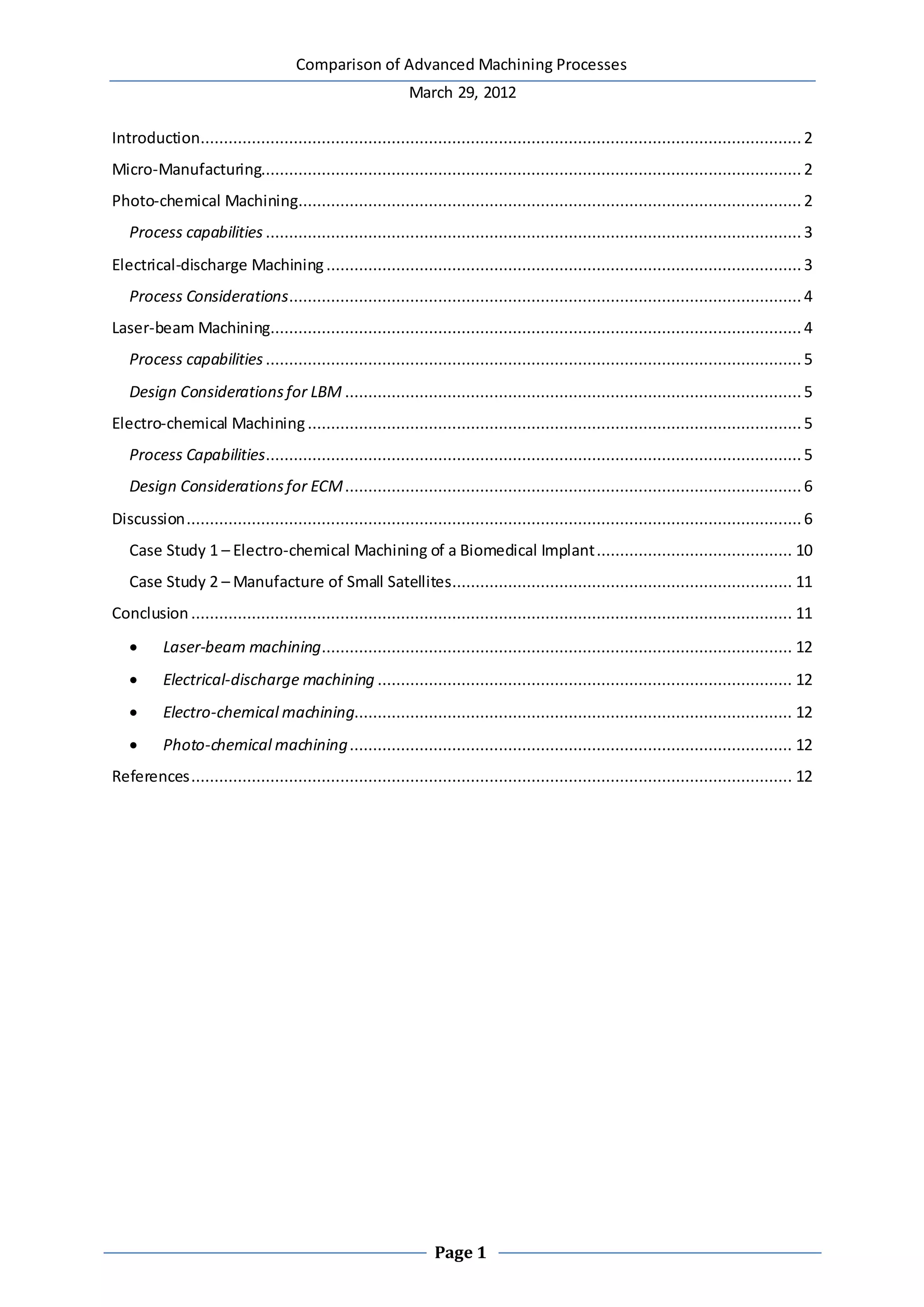
Some of the applicationsof laser manufacturingcan beseen in the table below;
Important parameters within LBM
are the reflectivity and thermal
conductivity of the workpiece
surfaceand its specific heatand
latent heats of melting and
evaporation. The lower these
quantities are,the more efficient
the process becomes.
The surfaceproduced by this
process is usually rough and produces a heat-affected zone, which, for critical applications,may have to be
removed or heat treated.
Laser Application Material
Micro-electronics packaging
Excimer
Lamp-pumped solid-state
Diode-pumped solid-state
CO2sealed or TEA
Via drilling and interconnect drilling
Via drilling and interconnect drilling
High volume via drilling, tuningquartz oscillators
Excising and scribing of circuitdevices, large panel viadrilling
Plastics, ceramics, silicon
Plastics, metal, ceramics, silicon
Plastics, metal, inorganic
Ceramics, plastics
Semiconductormanufacturing
Excimer
Solid-state
CO2 or TEA
UV-lithography, IC repair, thin films, wafer cleaning
IC repair, thin films, bulk machiningresistor and capacitor
trimming
Excising, trimming
Resist, plastics, metals, oxides silicon
Plastics, silicon, metals, oxides silicon,
thick film
Silicon
Data storage devices
Excimer
Diode-pumped solid-state
CO2 or TEA
Wire stripping air bearings, heads micro via drilling
Disk texturing servo etching micro via drilling
Wire stripping
Plastics, glass silicon ceramics plastics
Metal, ceramic metals, plastic
Plastics
Medical devices
Excimer
Solid-state
CO2 or TEA
Drilling catheters balloons, angioplastydevices, micro-orifice
drilling
Stents, diagnostics tools
Orifice drilling
Plastics, metals, ceramics, inorganics
Metals
Plastics
Communication and computer peripherals
Excimer
Solid-state
CO2 or TEA
Cellular phone, fibre gratings, flat panel annealing, ink jet heads
Via interconnect coating removal tape devices
Optical circuits
Plastics, metals, glass, silicon, inorganics
Plastics, metals, oxides, ceramics
Glass, silicon
FIG.3 –Thisdiagram showsthe components
of an electrical-discharge machining
operation.
FIG.4 –The diagram above illustratesthe
layout and operation ofalaser-beam
machining operation.
TABLE1 –The above table comparesthetypesoflaser used inLBM,their applicationsand the
typesofmaterial used.](https://image.slidesharecdn.com/85a9e6b9-2566-473b-94b9-ea0843bf3500-151123220017-lva1-app6891/85/Production-Techniques-2-advanced-machining-techniques-report-4-320.jpg)
![Comparison of Advanced Machining Processes
March 29, 2012
Page 5
Process capabilities – This process is widely used for drilling,trepanning,and cutting metals,non-metallic
materials,ceramics and compositematerials. Laser beammachininghas become an attractivealternativeto
traditional machiningmethods due to the cleanlinessof the operation and the abrasivenatureof composite
materials. Holes as small as 0.005mmwith a depth-to-diameter ratio of 50:1 have been produced in various
materials dueto this process. The laser is bestused for cutting and drillingand in order to achieve the best
results duringdrillingitis necessary to locatethe material within a toleranceof +/- 0.2mm of a focal point.[6]
Laser beam machiningis becomingincreasingly used in the electronics and automotive industries and was
used in the firststage of producingvanes for the Boeing 747 jet engines. The process is also developingin
areas such as welding,small-scaleand localised heattreating of metals and ceramics and the markingof parts,
such as letters, numbers, codes etc.[2] Laser-beam machiningis beingused in only exceptional cases such as
machiningvery small holes and cuttingcomplex profiles in thin,hard materials likeceramics,makingitideal
for use within the micro-manufacturingindustry.[6]
Design Considerations for LBM – Some general design guidelines for laser-beammachiningare;
Designs incorporatingsharp corners should beavoided as they can be difficultto produce
Deep cuts will producetapered walls
The reflectivity of a workpiece surfaceis an importantconsideration in thelaser-beammachining
process. Dull and unpolished surfaces arepreferabledue to the low reflectivity of the surface
Any adverseeffects on the properties of the machined materials caused by the high localised
temperatures occurringduringthe process and any heat-affected zones should be investigated before
the workpiece is used in its intended application,this is particularly importantfor critical
applications[2]
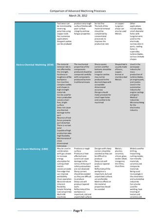
Electro-chemical Machining
Electro-chemical machining(ECM), in technical terms, is the reverse of electroplating. An electrolyte becomes
a current carrier and the high rate of electrolyte movement in the toll-workpiecegap washes metal ions away
from the workpiece before they have the chance to plate onto the tool. The tool-workpiece gap is typically 0.1
to 0.6mm in width and the cavity produced is the female mating image of the tool shape.
The shaped tool is most commonly made from brass,copper,bronze or stainlesssteel. The electrolyte is a
highly conductiveinorganic fluid such as sodiumnitrate. The inorganic liquid ispumped through the passages
in the tool at rates between 10 and 16 m/s. A DC power supply rangeof 10 to 25 V maintains current
densities.
The material removal rate of the electro-chemical machiningprocess
ranges between 1.5 and 4 mm3 per A-min and the tool penetration
rate is proportional to the current density. Within this process the
material removal rate is a function of the ion exchange rate and is
therefore not affected by the strength, hardness,or toughness of the
workpiece.
Process Capabilities – The concept of electro-chemical machiningwas
patented in 1929 and further developed through the 50s and 60s
where its importance as a manufacturingprocess was realised. The
process is nowgenerally used to machine complex cavities and shapes
FIG.5 –Thisdiagram showsthe electro-
chemical machining processin action.](https://image.slidesharecdn.com/85a9e6b9-2566-473b-94b9-ea0843bf3500-151123220017-lva1-app6891/85/Production-Techniques-2-advanced-machining-techniques-report-5-320.jpg)
![Comparison of Advanced Machining Processes
March 29, 2012
Page 6
in high strength materials and in particular theaerospaceindustry for the mass production of turbine blades,
jet engine parts and nozzles. Its use within the automotive and medical industries has also grown,producing
components such as engine castings,gears and knee replacement systems.
The process can be diverse in use as itis also used for machiningand finishingforging-diecavitiesand
producingsmall holes. Variationsof the process arealso used for turning, facing,milling,slotting,drilling,
trepanning, profilingand also in theproduction of continuous metal strips and webs. More recent applications
of the process includemicromachiningfor usein the electronics industry.
ECM leaves a burr-free, bright surfacefinish and therefore can also beused as a deburring process. Itdoes not
causethermal damage to the workpiece and the absenceof any tool force prevents the distortion of the part.
There is also no tool wear and the process is very capableof producingextremely complex shapes. On draw-
back or concern is the material properties of components produced usingECM, the mechanical properties of
ECM components should be compared carefully with products produced usingother material removal
production methods. [2] Usually very lowcurrent efficiencies,typically 10-20 %,are obtained and the surface
finish achieved is dependent on the material used,some materials,such as sodiumchloride,tend to leave an
etched effect on the surface. However, a surfacefinish,as fineas 0.1 micrometres, has been reportedly
produced with nickel-chromiumsteels. Accuracy and dimensional tolerancealso depends on the type of
material used duringthe process.[7]
Electro-chemical machiningsystems arenow availableas numerically controlled machiningcentres producing
high production rates, high flexibility and constantdimensional tolerances. ECM can also becombined with
electrical-dischargemachiningto develop a process called hybrid machining.
Design Considerations for ECM – General design guidelines for ECM are;
As the electrolyte tends to erode away sharp profiles,electro-chemical machiningis notsuited for
producingsharp squarecorners of flatbottoms
Controllingthe electrolyte flow is difficultresultingin irregular cavities notbeing produced to the
desired shape with acceptabledimensional accuracy
Designs should make provision for a small taper for holes and cavities to be machined[2]
Discussion
The advanced machiningprocesses described arebased on non-mechanical means of material removal. The
report has discussed chemical machiningwhere material is removed through the corrosiveaction of fluid,
electrochemical machiningwhere the material is removed through the action of an electrical power source
and also ion transfer within an electrolytic fluid and electrical dischargemachiningwhere material is removed
by melting small portions of the workpiece by a spark. High energy beams, such as those used in laser beam
machining,arebeginning to be used extensively with unique applications. Some of the typical parts made by
these processes include;
Skin panels for missiles and aircraft
Turbine blades
Nozzles
Parts with complex cavities and small-diameter deep holes
Dies
Laser cuttingof sheet metals
Cutting of thick metallic and non-metallic parts](https://image.slidesharecdn.com/85a9e6b9-2566-473b-94b9-ea0843bf3500-151123220017-lva1-app6891/85/Production-Techniques-2-advanced-machining-techniques-report-6-320.jpg)
![Comparison of Advanced Machining Processes
March 29, 2012
Page 7
These processes arewidely used in situations where material removal by mechanical means,such as chip
formation, abrasion,or microchipping, is notpossiblefor a variety of reasons which includeunsatisfactory
mechanical methods, economical issues,or traditional means arenot possible. Some of the reasons where
more advanced methods are required arelisted below;
The strength and hardness of the workpiece material arevery high, typically above400HB
The workpiece material is too brittle to be machined without damage to the workpiece. This is
common amongst heat treated alloys,glass,ceramics,and powder-metallurgy parts
The workpiece is too flexible or too slender to withstand forces in machiningor grinding. These parts
can also difficultto clamp in work holdingdevices
The shape of the part is complex and includes features such as internal and external profiles or holes
with high length-to-diameter ratios in very hard materials
Special surface finish and dimensional tolerance requirements exist that cannotpossibly beobtained
through any other manufacturingprocesses or areuneconomical through alternativeprocesses
The temperature rise duringprocessingand residual stresses developed in the workpiece are not
desirableor acceptable[2]
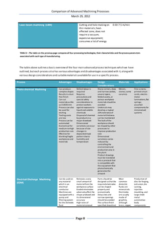
If any of these circumstances ariseduringmanufacturefor any product then one of the four previously
discussed processingtechniques may be used but each has its own characteristics and processparameters.
The typical material removal ratealso varies between the processingtechniques.
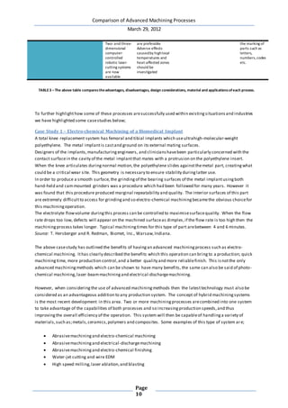
Process Characteristics Process parameters and
typical material removal
rate
Photo-chemical Machining Shallowremoval on large
flator curved surfaces;
blankingof thin sheets; low
toolingand equipment
cost; suitablefor low
production runs
0.0025-0.1 mm/min
Electrical-Discharge Machining (EDM) Shapingand cutting
complex parts made of
hard materials;some
surfacedamage may result;
also used as a grindingand
cutting process;expensive
toolingand equipment
V: 50-380; A: 0.1-500;
typically 300 mm3/min
Electrochemical Machining (ECM) Complex shapes with deep
cavities;highestrate of
material removal among
other non-traditional
processes;expensive
toolingand equipment;
high power consumption;
medium-to-high
production quantity
V: 5-25 DC A: 1.5-8
A/mm2; 2.5-12 mm/min,
depending on current
density](https://image.slidesharecdn.com/85a9e6b9-2566-473b-94b9-ea0843bf3500-151123220017-lva1-app6891/85/Production-Techniques-2-advanced-machining-techniques-report-7-320.jpg)
![Comparison of Advanced Machining Processes
March 29, 2012
Page
11
Machiningand blasting
Electro-chemical and electrical-dischargemachining(ECDM)
Machiningand formingprocesses,such as laser cuttingand punchingof sheet metal
Combinations of various forming,machiningand joiningprocesses
By usinga hybrid manufacturingsystem then the advantageous characteristicsof each process will be
achieved while also reducingsomeof the more problematic areas and gaininggreater control over the process
and its outcomes. However, this comes with its own economic issues which also stemfrom the singular
machiningprocesses involved.
The economic costs of a production run for a particular process depends on the costs of toolingand
equipment, the operating costs,the material removal rate required, the level of operator skill required,and
also the secondary and finishingoperations which may be necessary.
As chemical machiningisa very slowprocess,important costfactors can be considered as the costs of
reagents, maskants,and disposal,alongwith the cost of cleaningthe parts. In electrical-dischargemachininga
significantcostcan beincurred through the costto purchaseand periodically replaceelectrodes used within
the process.
The material removal rate and the production rate play a key role in the costof all of the above processes. The
costof toolingand equipment also varies considerably,alongwith the operator skill required. The high capital
investment required for the purchaseof machinery for these processes needs to be justified in terms of
production runs and the consideration if other production methods areviable.[2] However, these issues will
again be reduced if a hybrid system is to be considered. The use of such a hybrid system has been promoted
through the useof this system duringthe production of small satellites.
Case Study 2 – Manufacture of Small Satellites
There are several compellingreasons to reduce the sizeof satellites,nonegreater than the costof putting the
satelliteinto orbit. One of the main sources of weight within the satellitecomes from its propulsion system
which is necessary for changingits orbitor for correctingfor drift.
The production of miniatureparts for a satellite’s propulsion systemwould be extremely difficultthrough
conventional forming, casting,or machiningtechnologies. Furthermore, connecting the plumbingfor all of the
components would be extremely difficult,even with larger components. An attractive alternativeis to
produce the satelliteusingan integrated system, with fluid connections beingmade internally through a
photochemically etched and diffusion-bonded supporton which components are welded or mechanically
fastened.
Such fully integrated systems have resulted in satellitepropulsion systems which are less complex,more
robust, and reduced in sizewhen compared to those in previous designs. Source: R. Hoppe, VACCO Industries,
Inc.
Conclusion
The above discussion hasshown that there are many benefits to the company in usingadvanced machining
methods. The reduced production time, the quality of the partproduced and the complexity of shape
achieved will havefar reachingconsequences for the company. However the aimof this comparison report
was to outlinethe best choicefor use within the industry when consideringthe followingspecifications;
The equipment is to be used for the manufacture of micro-products](https://image.slidesharecdn.com/85a9e6b9-2566-473b-94b9-ea0843bf3500-151123220017-lva1-app6891/85/Production-Techniques-2-advanced-machining-techniques-report-11-320.jpg)
![Comparison of Advanced Machining Processes
March 29, 2012
Page
12
Materials to be dealt with include;thin sheet-metals, tool-steels,tungsten carbides,ceramics,glass,
polymers etc.
Bearingthis in mind then all four of the outlined techniques could be used within the industry;however, some
characteristicsof the processes need to be considered duringthe design stage of the micro-products;
Laser-beam machining – This process is beingroutinely used in many micro-manufactureindustries
in both material removal and joiningapplications. Thecharacteristics of the laser will determinethe
materials which can be processed,this is outlined in the tablein the section on laser-beammachining,
and a wide range of materials is available. The parameters to be chosen and controlled duringthe
process arewavelength, power, pulseduration,and pulserepetition rates. The process can produce
oxide-free surfaces which can aid weldingbuta rough surfaceand heat-affected zones will require
further processing.[8]
Electrical-discharge machining – The majority of micro-products arecreated usingelectrical-
dischargemachiningas thedimensional accuracy of the structures is superior to any other process.
Micro-EDM offers the possibility of producingfreeform microstructures in metals and in doped
silicon. The machiningcan bemodified for a specific production setup and quality can be controlled
by adjustingcertain parameters,as explained in the comparison tablein the discussion section. The
best outcome for the manufacture of micro-products would be to combine this technology with
another to create a hybrid system so that production of a wider variety of materials could takeplace
within the industry.[9]
Electro-chemical machining – The benefit of usingthis technique is the ability to process parts
without applyinga mask. Three-dimensional control of the tool duringproduction can resultin an
accuracy of less than 1 micrometre which makes this technology great for micro-manufacturingdue
to the accuracy and detail which can beachieved. This technology is considered to be a key future
technology for the manufacture of miniaturised products. However, similarly this techniquecan only
be applied to metals and semiconductors,meaning that other techniques for the manufacture of
micro-products in other materials mustbe considered,however for accuracy,which can be up to 10
nanometres, then the inclusion of this advanced machiningmethod is a must within any industry.[10]
Photo-chemical machining – This process is ideal for the manufacture of micro machined parts. The
advantages of the process arequite diverse but includetight tolerances,and low costtooling. Once
again however, this process is only applicableto metallic materials. For this industry itshould be
combined with other advanced machiningtechnologies to produce the best outcome. The inclusion
of this technology in the industry can also introducethe process of etching onto particular
components, resultingin more detailed and high quality,visually appealingproducts.[11]
To conclude,we have found that after a lengthy comparison all four of the technologies can be used within our
industry. Each has its own unique advantages which would all bebeneficial within the manufacture of micro-
products. However, to fully utilisethe potential of all of these advanced machiningmethods then the best
suggestion to is investin a hybrid manufacturingsystem which will producehigh quality products and combine
the advantageous characteristicsof all of the mentioned technologies to resultin a competitive and more
responsiveindustry.
References
[1] – www.pcmi.org - accessed 29/3/12
[2] – Kalpakjian,S.,and Schmid, S. R., 2010,ManufacturingEngineering and technology, Pearson,Singapore
[3] - http://www.strath.ac.uk/dmem/research/researchunits/ufg/micro-manufacturingtechnology/ - accessed
29/03/12](https://image.slidesharecdn.com/85a9e6b9-2566-473b-94b9-ea0843bf3500-151123220017-lva1-app6891/85/Production-Techniques-2-advanced-machining-techniques-report-12-320.jpg)
![Comparison of Advanced Machining Processes
March 29, 2012
Page
13
[4] -
http://www.themetallurgist.co.uk/articles/chemical_milling_chemical_blanking_and_photochemical_blanking
.shtml - accessed 29/03/12
[5] - http://www.engineersedge.com/edm.shtml - accessed 29/03/12
[6] - http://indianjohn.hubpages.com/hub/laser-beam-machining - accessed 29/03/12
[7] - http://electrochem.cwru.edu/encycl/art-m03-machining.htm - accessed 29/03/12
[8] - http://www.micromanufacturing.net/didactico/Desarollo/microtechnologies/1-7-micromanufacturing-
technology-classification/1-7-2-energy-assisted-processes/1-7-2-1-laser-bea - accessed 29/03/12
[9] - http://www.mech.kuleuven.be/micro/topics/edm/ - accessed 29/03/12
[10] - http://www.cnrs.fr/cw/en/pres/compress/usinage.html - accessed 29/03/12
[11] - http://photochemicalmachining.com/2006/10/photo-chemical-machining.html - accessed 29/03/12
Casestudy 1 - T. Hersberger and R. Redman, Biomet, Inc., Warsaw,Indiana.
Casestudy 2 - R. Hoppe, VACCO Industries,Inc.
FIG.1 – www.stencilsunlimited.com - accessed 29/03.12
FIG.2 -
http://www.themetallurgist.co.uk/articles/chemical_milling_chemical_blanking_and_photochemical_blanking
.shtml - accessed 29/03/12
FIG.3 - http://www.lanl.gov/residual/edm.shtml - accessed 29/03/12
FIG.4 - http://www.scielo.br/scielo.php?script=sci_arttext&pid=S1678-58782004000100007 –accessed
29/03/12
FIG.5 -
http://www.themetallurgist.co.uk/articles/the_role_of_electrochemical_machining_ecm_in_industrial_metall
urgy.shtml - accessed 29/03/12
Table 1 - http://web.iitd.ac.in/~suniljha/LaserBeamMachining.pdf - accessed 29/03/12](https://image.slidesharecdn.com/85a9e6b9-2566-473b-94b9-ea0843bf3500-151123220017-lva1-app6891/85/Production-Techniques-2-advanced-machining-techniques-report-13-320.jpg)